


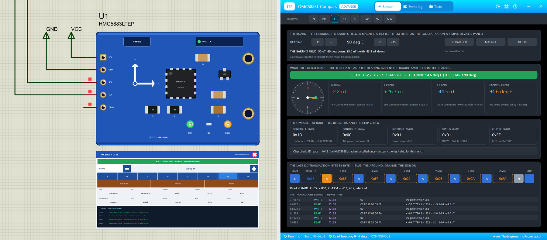
HMC5883L / QMC5883L Compass Library for Proteus V1.0: GY-271 Module


Hello friends, I hope you all are doing great. Today, I am going to share the new HMC5883L / QMC5883L Compass Library for Proteus V1.0. The GY-271 is the small blue compass module that you find in robots, rovers, drones and digital compass projects. It measures the Earth's magnetic field on three axes, and from two of them the Arduino works out the heading: how many degrees the board points away from north. There is a catch: GY-271 boards come with two different chips, the HMC5883L and the QMC5883L, and a sketch written for one does not work on the other. Now you can build and test both in Proteus.
Behind the parts sit our own models, not parts that show a number. Each chip answers the Arduino exactly as its datasheet says, with its own address, its own registers and its own byte order. You turn the board to any heading, put a magnet on it, tilt it, or turn it a full circle while the sketch calibrates. You get four devices: each chip as a Simple device with a live STATUS panel and the board's controls, and as an Advance device with a pop-up window and the test tools. The demo runs the Adafruit HMC5883 Unified library on our Arduino UNO V4.0 and finds whichever chip is on the board.
NOTICE: a compass is easy to fake: hand the Arduino a heading from a property. We wanted more. Our GY-271 feels the Earth's field from the direction the board points, adds the magnet and the tilt, and turns the result into the chip's own counts and registers, so the Adafruit library reads it exactly as on your desk, and a wrong address, a wrong byte order or a magnet next to the board fails exactly as it does there. It took our team a lot of hard work. Your feedback is the fuel that keeps us going, so please tell us what you think in the comments below or in the GY-271 compass board of our forum. And if our free libraries help you, you can buy us a coffee. So, let's get started with the HMC5883L / QMC5883L Compass Library for Proteus V1.0:
What is the GY-271 Compass Module?
The GY-271 is a breakout board for a 3-axis magnetometer: a chip that measures the magnetic field along X, Y and Z. The Earth's field is weak, about 25 to 65 uT depending on where you are, and it does not lie flat: it points north and down into the ground. A compass needs only the part that lies flat, so with the board level, X and Y give the heading and Z carries most of the downward part. The board adds a 3.3 V regulator and the I2C pull-ups, so it runs from the 5 V of an Arduino too. One gauss is 100 uT, which is why the datasheets talk about gauss and the sketches print uT.
If you only need to know whether a magnet is near, a simpler sensor does it, as in our Magnetic Hall Effect Sensor (KY-024) Library for Proteus and our Magnetic Reed Switch Library for Proteus. For the tilt, look at our ADXL345 Accelerometer Library for Proteus, or at the MPU6050 in our Introduction to MPU6050 and our MPU6050 Library for Proteus.
| HMC5883L | QMC5883L | |
|---|---|---|
| Maker | Honeywell | QST |
| I2C address | 0x1E | 0x0D |
| Identity | ID "H43" in 0x0A to 0x0C | chip ID 0xFF in 0x0D |
| Data | X, Z, Y from 0x03, high byte first, 12 bits | X, Y, Z from 0x00, low byte first, 16 bits |
| Ranges | +-0.88 to +-8.1 Ga (1370 to 230 counts a gauss) | +-2 or +-8 G (12000 or 3000 counts a gauss) |
| Data rate | 0.75 to 75 Hz (15 Hz after power-on) | 10, 50, 100 or 200 Hz |
| Start | MR = 0x00: continuous | SET/RESET = 0x01, then CONTROL 1: continuous |
| Marking on the chip | L883 | DA 5883 |
| Devices | HMC5883LTEP (Simple), HMC5883LADVTEP (Advance) | QMC5883LTEP (Simple), QMC5883LADVTEP (Advance) |
HMC5883L or QMC5883L? The Classic GY-271 Trap
The HMC5883L from Honeywell was the original chip of the GY-271. Most boards sold today carry the QMC5883L from QST instead, often with "HMC5883L" still printed on them. The two chips do the same job, but everything a sketch touches is different: the address, the registers, the order of X, Y and Z and the order of the bytes. An HMC5883L library on a QMC5883L board talks to 0x1E, nobody answers, and the sketch prints the same small numbers forever. Our model catches this trap, counts the calls and explains it in red. Look at the chip to tell them apart: L883 is an HMC5883L, DA 5883 a QMC5883L. Or let the sketch ask, as our demo does.
From X and Y to a Heading
With the board flat, the heading is atan2(Y, X) in degrees, plus 360 when it comes out negative. Two things pull it off. A magnet, a steel screw or a speaker on the board adds a field of its own that turns with the board; this is hard iron, and it is removed by turning the board a full circle, noting the minimum and the maximum of X and Y, and subtracting the centre of each. A tilt mixes the large downward part of the Earth's field into X and Y; that needs an accelerometer and tilt compensation. Last, the compass points to magnetic north, so for true north you add the declination of your place.
What's New in HMC5883L / QMC5883L Compass Library for Proteus V1.0
- The real module, twice: the blue GY-271 with the HMC5883L or the QMC5883L, its regulator, the pull-ups, the capacitors and the X / Y arrows, drawn at about three times its real size, with the header VCC, GND, SCL, SDA and DRDY.
- Two styles: Simple devices with a STATUS panel and Advance devices with a pop-up window; the PWR, I2C and DRDY LEDs and the panel button sit on the board itself.
- The real HMC5883L: CRA, CRB and MR, the eight gains and their overflow, continuous, single and idle, the data high byte first, RDY and LOCK, the ID, the pointer's roll-over, the self-test bias and the DRDY pulse.
- The real QMC5883L: CONTROL 1 and 2, SET/RESET, the two ranges, the data rates and the oversampling, the data low byte first, DRDY, OVL and DOR, the temperature, the soft reset and the DRDY pin.
- The world on the panel: the board's heading in 15 degree steps or at the eight points, a MAGNET on the board, a 30 degree TILT and a full turn in 8 s (ROTATE 360); the Earth's field and its inclination as properties.
- The GY-271 trap caught: calls to the other chip's address are counted and shown in red, while a single probe, as in an I2C scan, is only noted.
- Mistake detection: data read before any measurement, a write to a read-only register, a field beyond the range, LOCK after a partial read, continuous mode without SET/RESET.
- Four test tools on the Advance devices: I2C, Readings, Heading & calibration, and Registers.
- A two-node demo on our Arduino UNO V4.0: one sketch that finds either chip, with CAL, DECL, RAW and TRAP.
- A compact package: about 1.28 MB, without the C++ source code of the model.
Four Devices: Simple and Advance
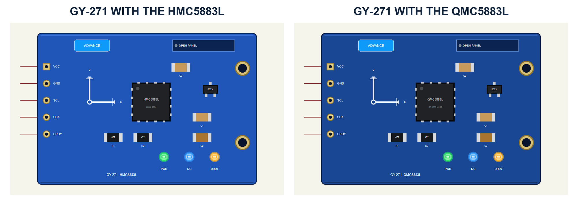
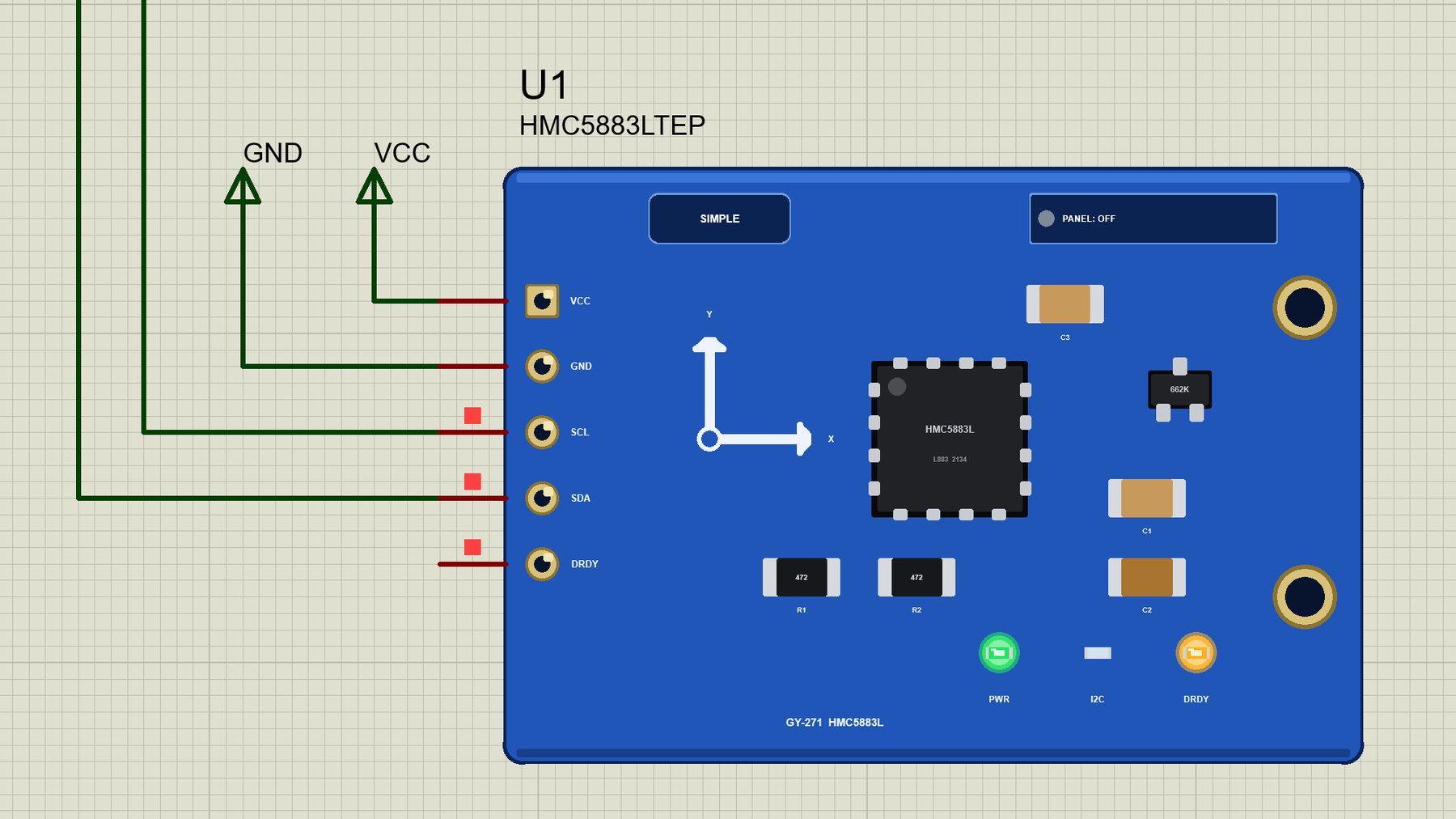
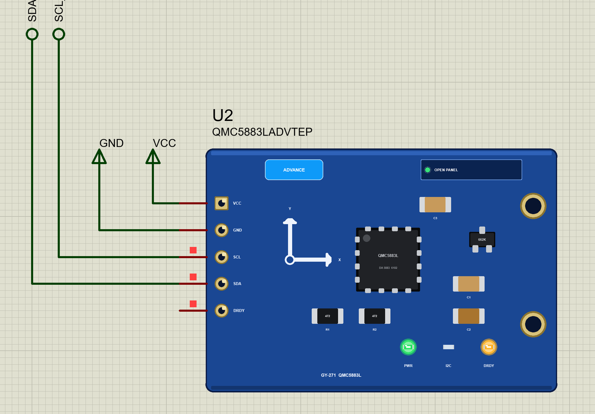
Both boards look alike, as the real ones do; the chip in the middle tells them apart, with its marking L883 or DA 5883 and the name printed on the board. Around it are the 662K regulator, the pull-ups R1 and R2 (472, 4.7 kohm), the capacitors C1 to C3 and the axis marks: X to the right and Y up. The header on the left has the five pins of the real GY-271.
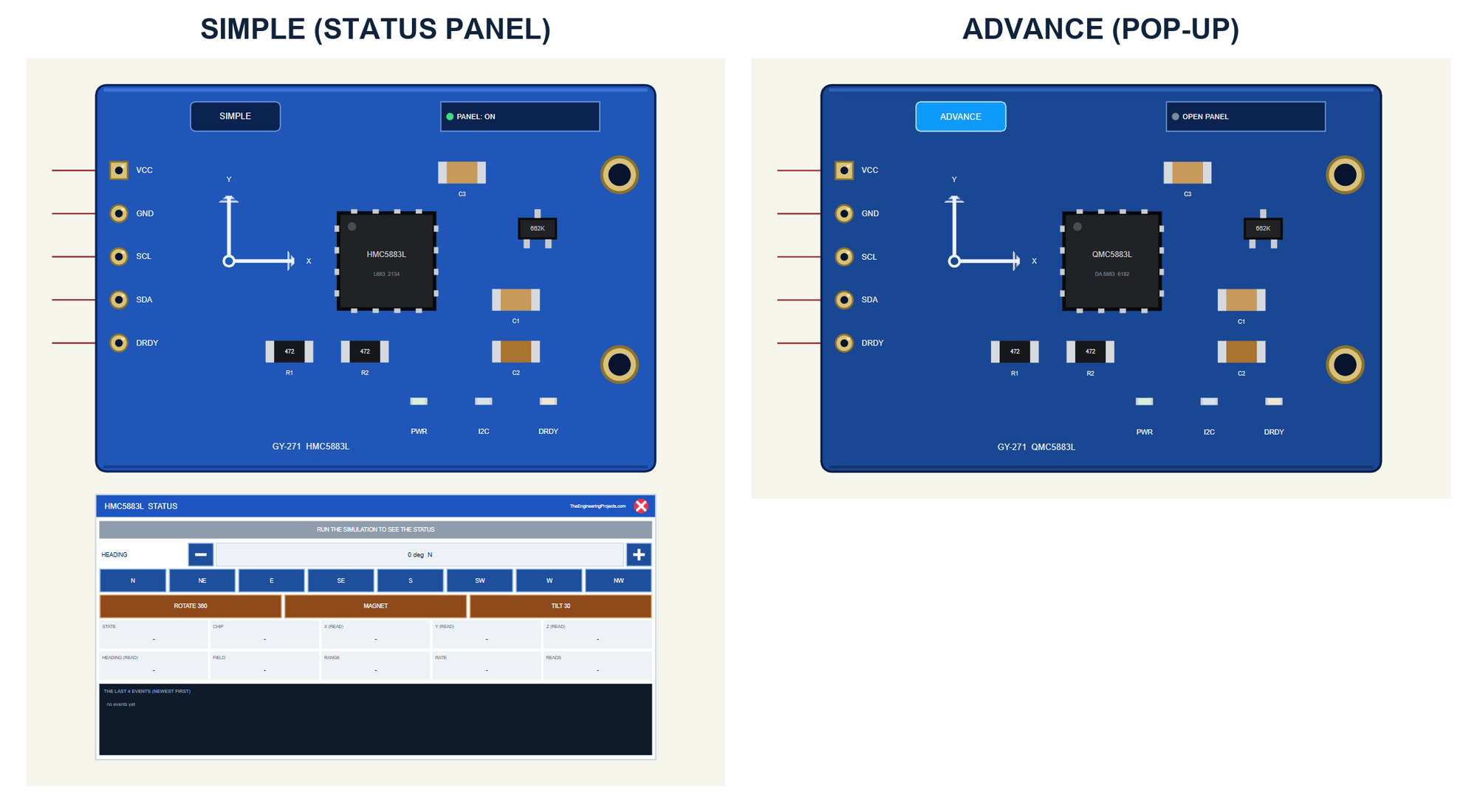
| Simple | Advance | |
|---|---|---|
| HMC5883L | HMC5883LTEP | HMC5883LADVTEP |
| QMC5883L | QMC5883LTEP | QMC5883LADVTEP |
| On the schematic | The module and the STATUS panel | The module |
| The board's heading, magnet and tilt | On the STATUS panel | In the pop-up |
| Status | Banner, 10 readouts, the last 4 events | A pop-up: Sensor, Event log, Tests |
Download HMC5883L / QMC5883L Compass Library for Proteus
Click the button below to download GY-271-Compass-Library-for-Proteus-v1.0.zip (about 1.28 MB, without the C++ source code of the model):
HMC5883L / QMC5883L Compass Library for Proteus V1.0: GY-271 Module- README.txt: the devices, installation, the demo, wiring, the test tools and real hardware.
- Proteus Library Files:
TEPCOMPASS.LIBandArduinoV4TEP.LIBfrom our Arduino Library for Proteus V4.0. - Proteus Model Files:
TEPCOMPASS.DLLandTEPARDUINO.DLL. - Proteus Simulation:
GY-271-Compass-ArduinoUnoV4.pdsprj,GY271_Compass_Demo.hexand copies of the two DLLs. - Arduino Code:
GY271_Compass_Demo.ino. It needs the Adafruit HMC5883 Unified library from the Library Manager of the Arduino IDE, only if you want to change the sketch.
No Proteus yet? Read How to Download and Install Proteus 7 and 8. New to libraries? Follow How to Install a New Library in Proteus.
How to Install HMC5883L / QMC5883L Compass Library for Proteus
- Close Proteus and extract the whole zip file, for example to your Desktop.
- Copy the two files from Proteus Library Files into the LIBRARY folder of Proteus (usually
C:\Program Files (x86)\Labcenter Electronics\Proteus 8 Professional\LIBRARY). - Copy
TEPCOMPASS.DLLandTEPARDUINO.DLLfrom Proteus Model Files into the MODELS folder. - Delete
TEPCOMPASS.IDXfrom the LIBRARY folder if it is there. - Start Proteus, press P and search for 5883.
Tip: keep the Proteus Simulation folder together, because the project needs its .hex file and the DLLs beside it. The library is tested in Proteus 8.5; Proteus 7 is not supported.
The GY-271 Parts in Proteus
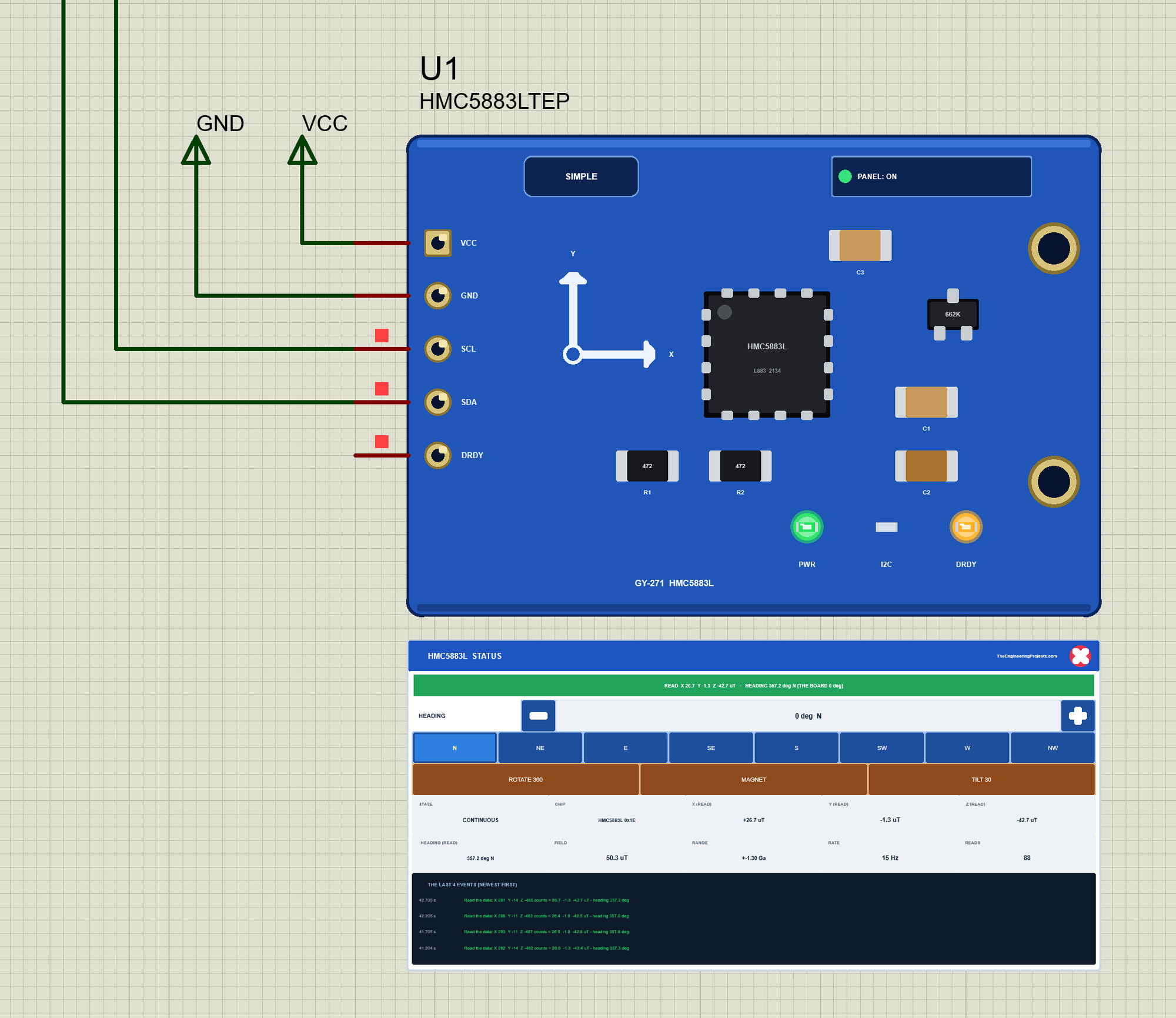
Three LEDs sit on the module's board: PWR while VCC is there, I2C, which flashes when the Arduino talks to the module, and DRDY, which flashes at new data. Next to the SIMPLE or ADVANCE badge is the panel button. The LEDs, the badge, the button and the panels are TEP additions; the real module has none of them.
The Simple device adds the STATUS panel. Its banner shows what the sketch read and the heading it gives, next to the board's real heading; it turns amber while the board turns and red for the trap or a warning. Below it are the board's controls: HEADING with - and + (15 degrees a click), the eight points from N to NW, and three actions: ROTATE 360, MAGNET and TILT 30. Ten readouts follow - the state, the chip and its address, X, Y and Z as read, the heading as read, the field, the range, the data rate and the reads - and the last four events.
The red X closes the STATUS panel, and the PANEL button on the board opens it again:
The Advance devices keep the schematic clean: only the module. Their live data opens in a pop-up window at Run, and the OPEN PANEL button on the board brings the window back. The properties set the start: HEADING (0 by default), FIELD (the Earth's field, 50 uT), INCLINATION (how far it points down, 60 degrees) and NOISE (1, about 0.2 uT).
The Demo Circuit
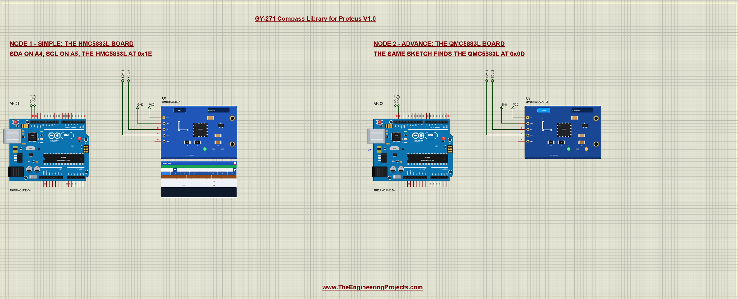
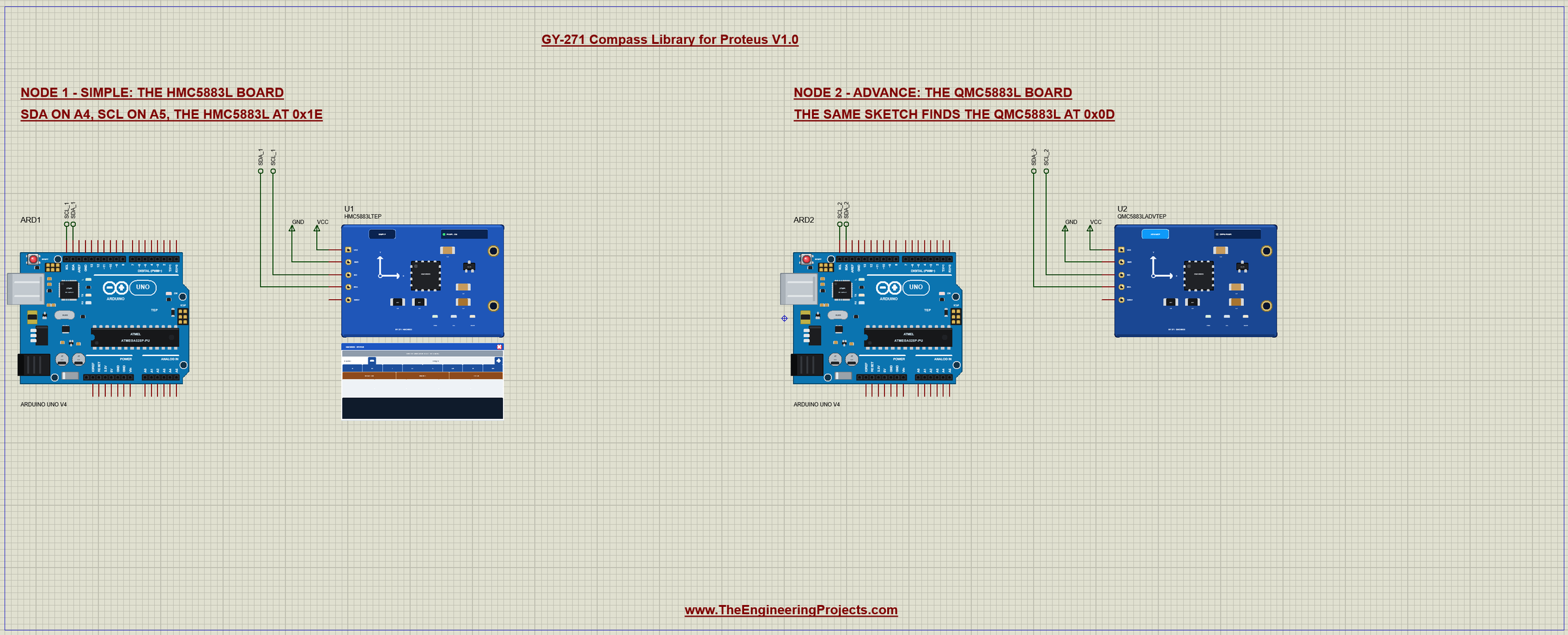
The demo project has two nodes. Each one is an Arduino UNO V4.0 from our Arduino UNO Library for Proteus V4.0 with a GY-271 on its SDA and SCL pins, which are A4 and A5. Node 1 carries the HMC5883L and starts facing north; node 2 carries the QMC5883L and starts facing north-east. Both UNOs run the same GY271_Compass_Demo.hex, which shows the point of the demo: one sketch that works on both kinds of GY-271.
Wiring
| Module | Arduino UNO |
|---|---|
| VCC | 5V (the regulator gives the chip 3.3 V) |
| GND | GND |
| SCL | A5 (the SCL pin) |
| SDA | A4 (the SDA pin) |
| DRDY | open (or an input for the new-data signal) |
In Proteus, SDA and SCL reach their UNO through net labels, SDA_1 and SCL_1 for node 1 and SDA_2 and SCL_2 for node 2. The Wire library turns on the UNO's internal pull-ups, which hold the I2C bus HIGH in the simulation. DRDY stays open: the HMC5883L pulses it low at each new sample, and the QMC5883L holds it high while new data waits. The serial monitor needs no wires at all, because it is built into the UNO V4.0.
The Arduino Code
The demo sketch uses the Adafruit HMC5883 Unified library (version 1.2.4) with Adafruit Unified Sensor for the HMC5883L, and plain Wire for the QMC5883L. New to Arduino? Start with Arduino Tutorial for Beginners and Introduction to Arduino UNO. The sketch begins with Wire and the two Adafruit headers:
#include <Wire.h>
#include <Adafruit_Sensor.h>
#include <Adafruit_HMC5883_U.h>
The Adafruit library only talks to 0x1E, and its begin() returns true whatever is on the bus. So the sketch first asks which chip is there: the HMC5883L answers at 0x1E with the letters "H43" in its ID registers, the QMC5883L at 0x0D with the chip ID 0xFF:
ChipType findChip() {
  if (probe(HMC_ADDR) && readReg(HMC_ADDR, 0x0A) == 'H' && readReg(HMC_ADDR, 0x0B) == '4' && readReg(HMC_ADDR, 0x0C) == '3') return HMC;
  if (probe(QMC_ADDR) && readReg(QMC_ADDR, 0x0D) == 0xFF) return QMC;
  return NONE;
}
For the HMC5883L, hmc.begin() sets continuous mode and the gain of plus or minus 1.3 Ga. The QMC5883L is set up by hand, with the same two writes the QMC5883LCompass library uses: SET/RESET to 0x01, the datasheet's value, then CONTROL 1 to 0x1D for continuous mode, 200 Hz, plus or minus 8 G and an oversampling of 512:
void qmcBegin() {
  writeReg(QMC_ADDR, 0x0B, 0x01);
  writeReg(QMC_ADDR, 0x09, 0x1D);
}
Reading the field is where the two chips differ most. getEvent() reads the HMC5883L's six bytes and returns uT. For the QMC5883L the sketch reads six bytes from 0x00, puts each pair together low byte first, and divides by 30, because at plus or minus 8 G one uT is 30 counts:
bool readField(float& x, float& y, float& z) {
  if (chip == HMC) {
    sensors_event_t e;
    hmc.getEvent(&e);                          // X, Z, Y high byte first, in uT
    x = e.magnetic.x; y = e.magnetic.y; z = e.magnetic.z;
    return true;
  }
  if (chip == QMC) {
    Wire.beginTransmission(QMC_ADDR);
    Wire.write(0x00);                          // X LSB
    Wire.endTransmission();
    Wire.requestFrom(QMC_ADDR, (uint8_t)6);
    int16_t v[3];
    for (uint8_t i = 0; i < 3; i++) {          // X, Y, Z low byte first
      const uint8_t lo = Wire.read();
      const uint8_t hi = Wire.read();
      v[i] = (int16_t)(hi << 8 | lo);
    }
    x = v[0] / 30.0; y = v[1] / 30.0; z = v[2] / 30.0;   // +-8 G: 3000 counts a gauss = 30 counts a uT
    return true;
  }
  return false;
}
The heading comes from X and Y, minus the hard-iron offsets that CAL finds, plus the declination that DECL sets:
float heading(float x, float y) {
  float h = atan2(y - offY, x - offX) * 180.0 / PI + decl;
  if (h < 0) h += 360;
  if (h >= 360) h -= 360;
  return h;
}
The HEX file is in the package, so you do not need the Arduino IDE to run the demo. To change the sketch, install "Adafruit HMC5883 Unified" from the Library Manager, open the sketch in the Arduino IDE and export the compiled binary, as in How to get the HEX file from Arduino. It needs 14,792 bytes of flash and 606 bytes of RAM.
The Serial Monitor
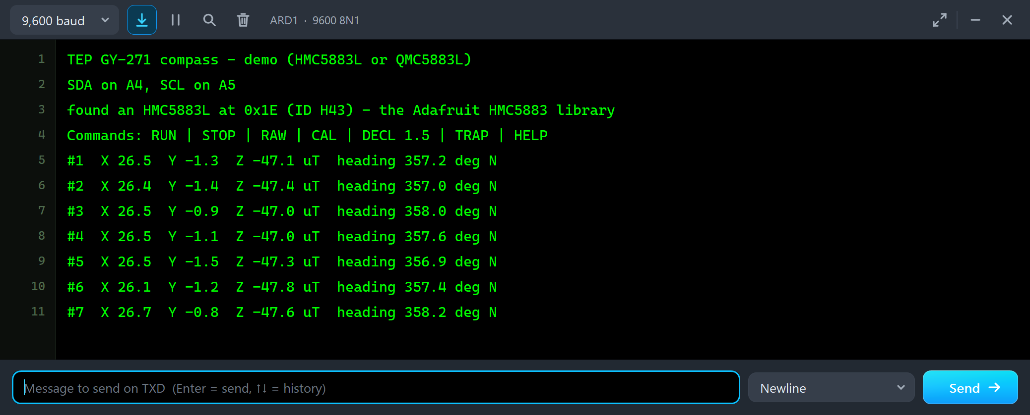
Both UNOs have the serial monitor built in, and it opens at Run. The screenshots use its Simple interface. Node 1 starts like this:
TEP GY-271 compass - demo (HMC5883L or QMC5883L)
SDA on A4, SCL on A5
found an HMC5883L at 0x1E (ID H43) - the Adafruit HMC5883 library
Commands: RUN | STOP | RAW | CAL | DECL 1.5 | TRAP | HELP
#1  X 26.5  Y -1.3  Z -47.1 uT  heading 357.2 deg N
#2  X 26.4  Y -1.4  Z -47.4 uT  heading 357.0 deg N
#3  X 26.5  Y -0.9  Z -47.0 uT  heading 358.0 deg N
#4  X 26.5  Y -1.1  Z -47.0 uT  heading 357.6 deg N
#5  X 26.5  Y -1.5  Z -47.3 uT  heading 356.9 deg N
The board faces north, so X carries the horizontal field, Y reads about zero and Z holds the large downward part. Two things to note. The heading reads about 357 instead of 0: each chip has a small offset of its own, as a real one does, and CAL removes it. And Z prints about 47 uT where the chip measures about 42: the Adafruit library divides Z by 980 counts a gauss, while the datasheet says 1090 for this gain, so Z prints about 11 % high. X and Y are divided by 1100, close to 1090, and the heading is not affected. Node 2 found the other chip:
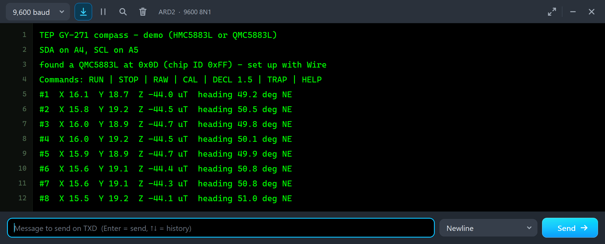
found a QMC5883L at 0x0D (chip ID 0xFF) - set up with Wire
Commands: RUN | STOP | RAW | CAL | DECL 1.5 | TRAP | HELP
#1  X 16.1  Y 18.7  Z -44.0 uT  heading 49.2 deg NE
#2  X 15.8  Y 19.2  Z -44.5 uT  heading 50.5 deg NE
#3  X 16.0  Y 18.9  Z -44.7 uT  heading 49.8 deg NE
#4  X 16.0  Y 19.2  Z -44.5 uT  heading 50.1 deg NE
Turn the Board
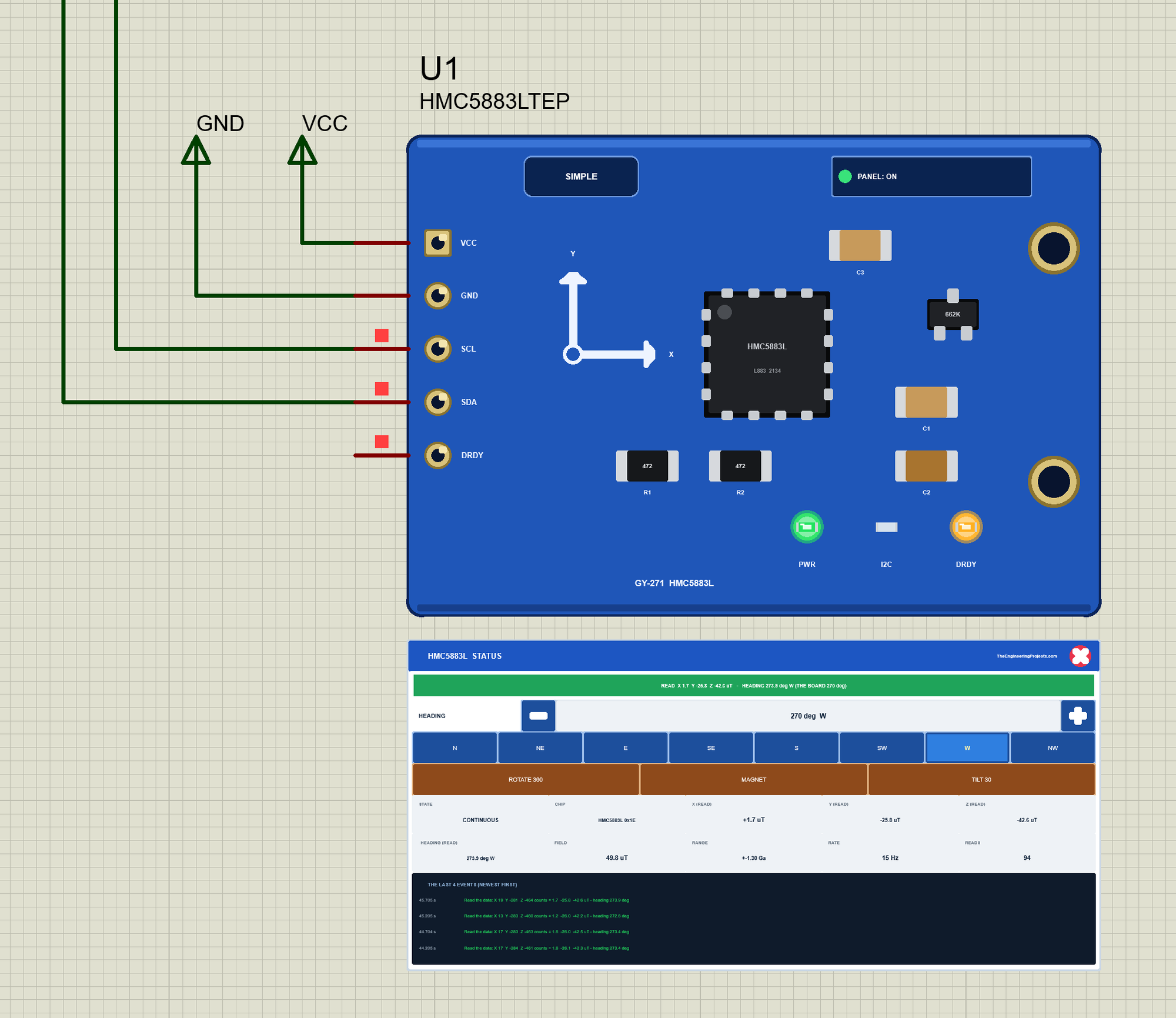
Now let's turn the board while the simulation runs. We clicked W on U1's STATUS panel with the mouse:
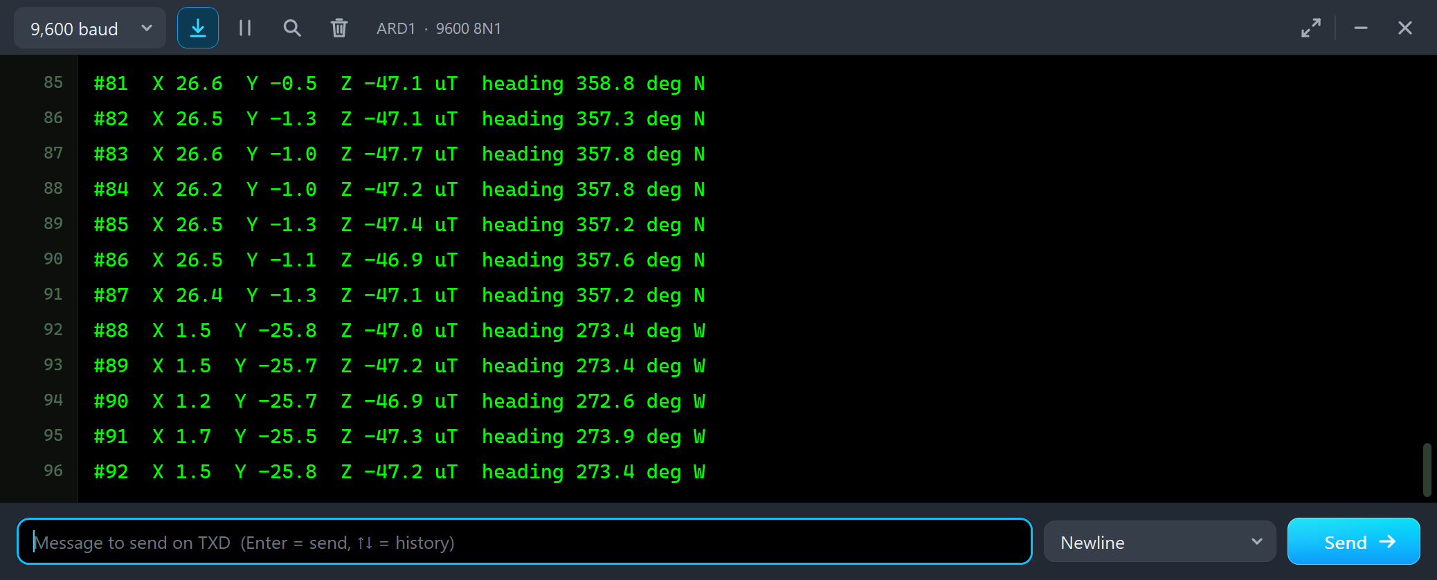
#85  X 26.5  Y -1.3  Z -47.4 uT  heading 357.2 deg N
#86  X 26.5  Y -1.1  Z -46.9 uT  heading 357.6 deg N
#87  X 26.4  Y -1.3  Z -47.1 uT  heading 357.2 deg N
#88  X 1.5  Y -25.8  Z -47.0 uT  heading 273.4 deg W
#89  X 1.5  Y -25.7  Z -47.2 uT  heading 273.4 deg W
#90  X 1.2  Y -25.7  Z -46.9 uT  heading 272.6 deg W
The horizontal field moved from X to minus Y, and the heading followed: 273.4 deg W, again a few degrees off because of the chip's offset. Z did not change, because the board stayed flat. Then two clicks on the heading's +:
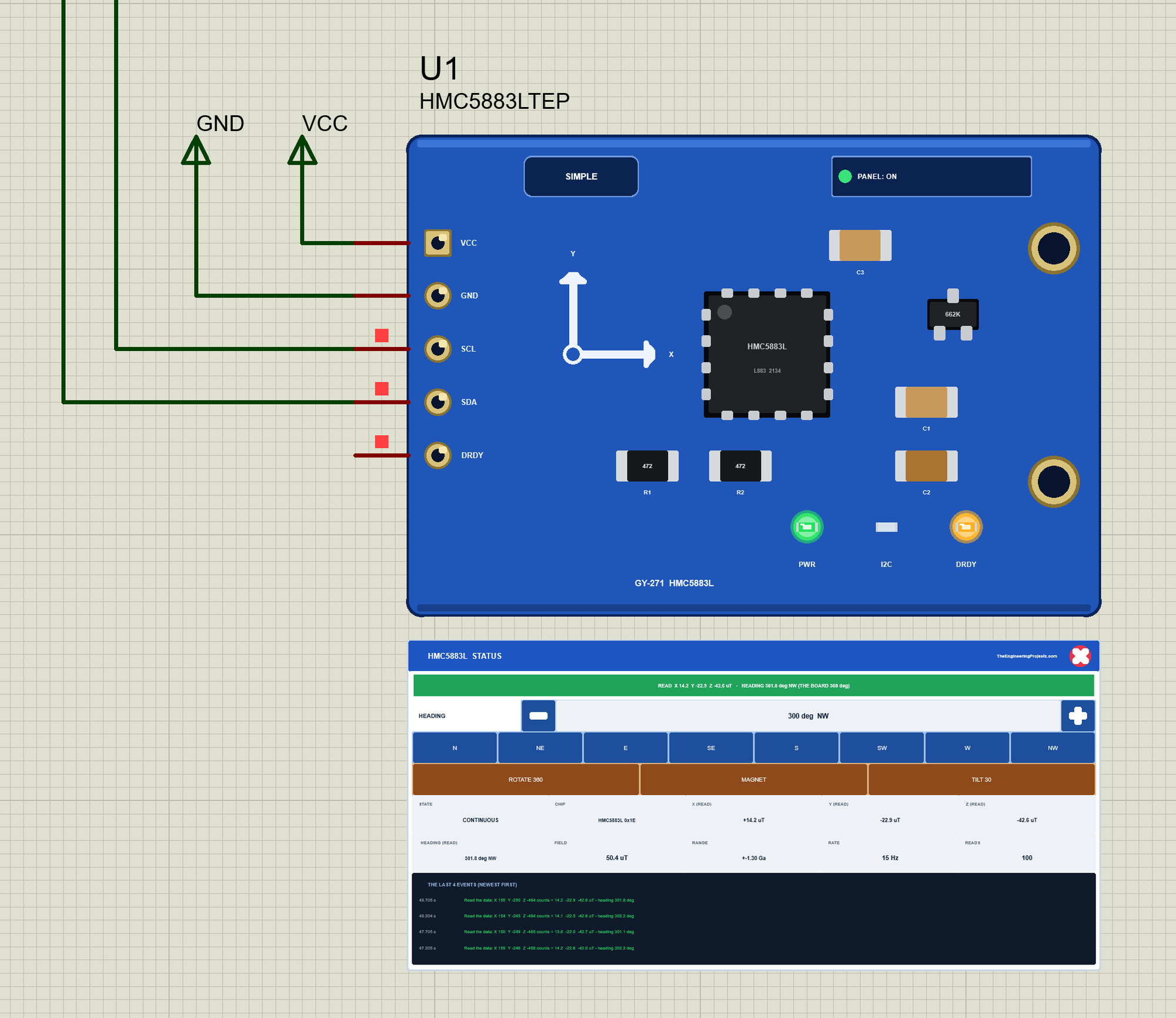
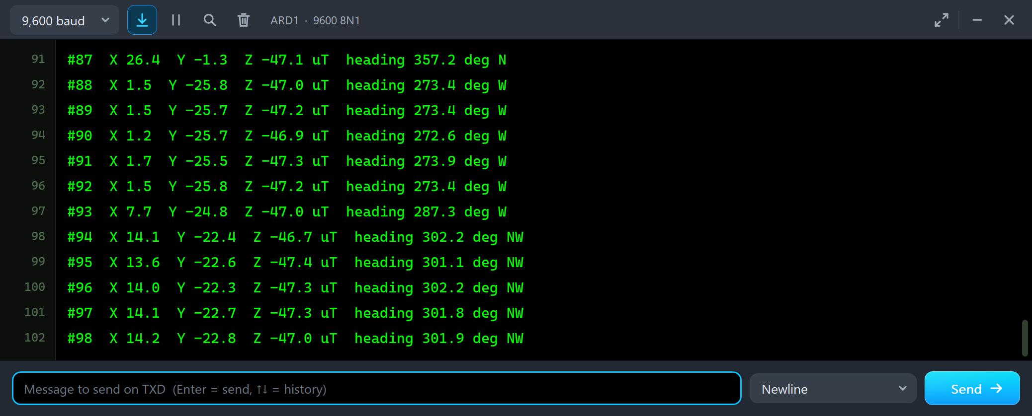
#92  X 1.5  Y -25.8  Z -47.2 uT  heading 273.4 deg W
#93  X 7.7  Y -24.8  Z -47.0 uT  heading 287.3 deg W
#94  X 14.1  Y -22.4  Z -46.7 uT  heading 302.2 deg NW
#95  X 13.6  Y -22.6  Z -47.4 uT  heading 301.1 deg NW
#96  X 14.0  Y -22.3  Z -47.3 uT  heading 302.2 deg NW
Each click is 15 degrees, and the reading follows step by step: 287.3, then about 302. A real compass never jumps like this, of course; the panel turns the board at once so that each step is easy to see.
A Magnet on the Board
Now the first thing that pulls a compass off. We clicked MAGNET: a small magnet that sits on the board and turns with it, adding X +35, Y -22 and Z +18 uT:
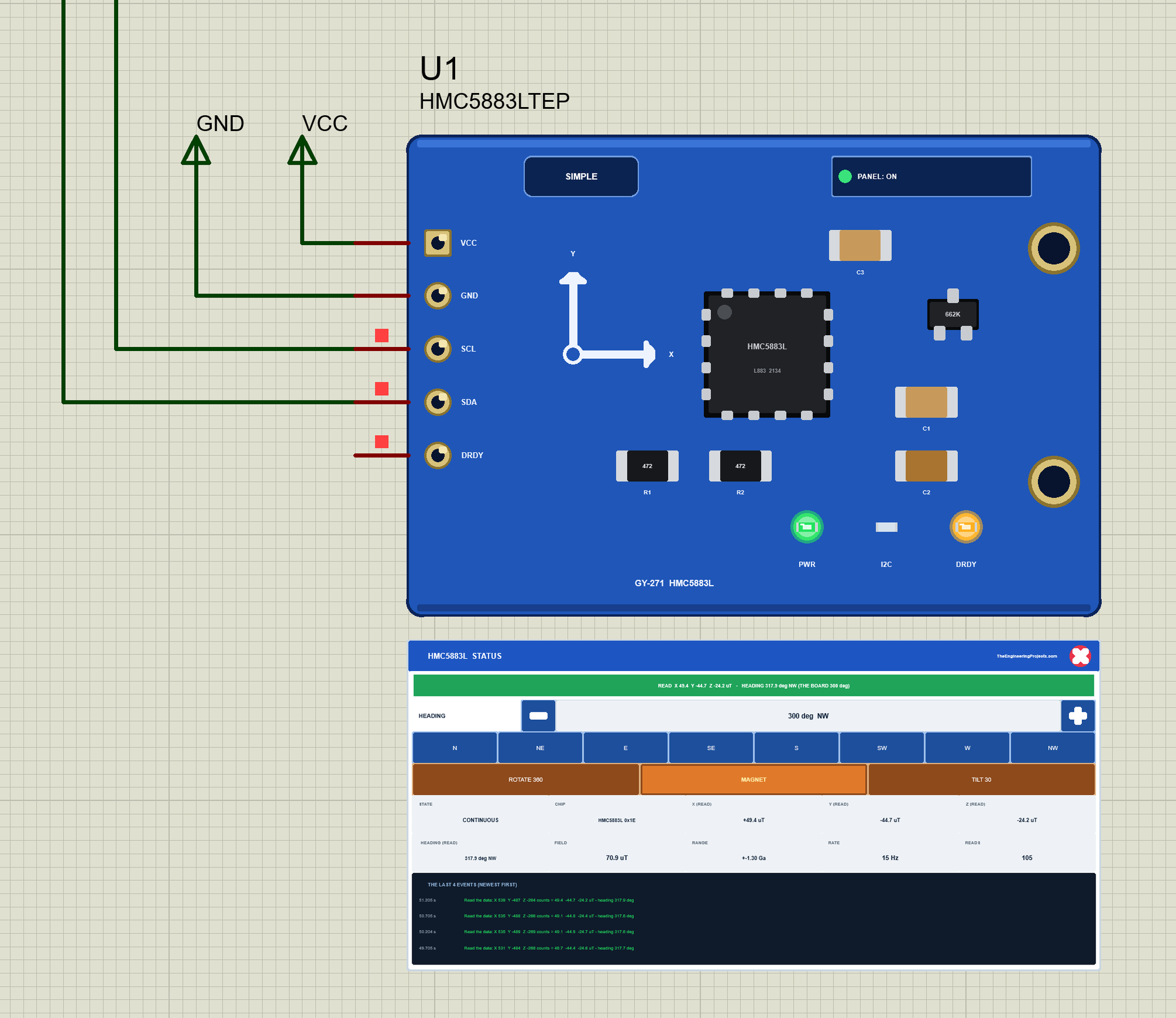
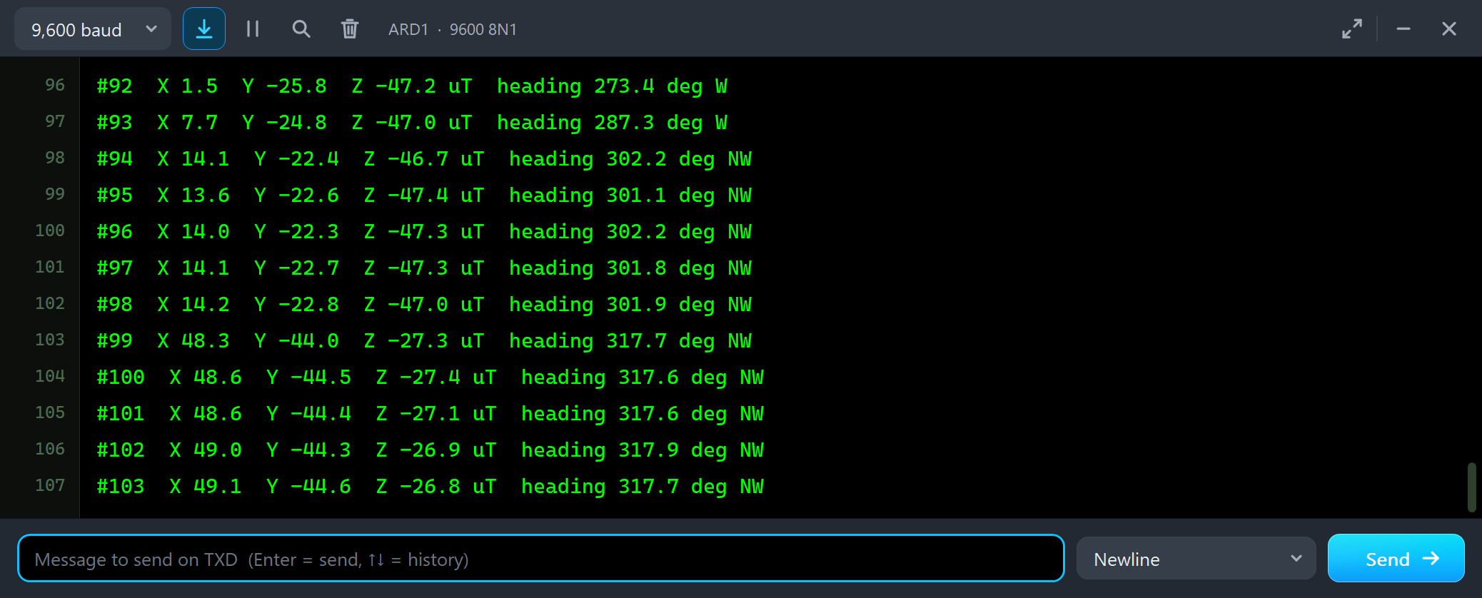
#97  X 14.1  Y -22.7  Z -47.3 uT  heading 301.8 deg NW
#98  X 14.2  Y -22.8  Z -47.0 uT  heading 301.9 deg NW
#99  X 48.3  Y -44.0  Z -27.3 uT  heading 317.7 deg NW
#100  X 48.6  Y -44.5  Z -27.4 uT  heading 317.6 deg NW
#101  X 48.6  Y -44.4  Z -27.1 uT  heading 317.6 deg NW
The board did not move, but the heading moved by 16 degrees. The magnet's field is larger than the flat part of the Earth's field, about 25 uT here, so it can pull the heading anywhere; how far depends on the direction the board points. This is why a compass is mounted away from motors, speakers and steel screws, and calibrated where it is mounted.
RAW and TRAP on the HMC5883L
RAW reads the six data bytes in one go and decodes them the chip's way. TRAP runs the Adafruit library's begin() and getEvent() on whatever chip is on the board. On node 1 we typed both:
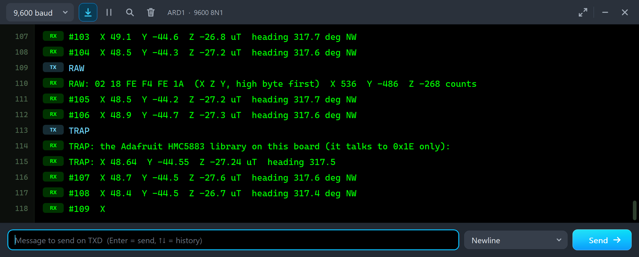
RAW
RAW: 02 18 FE F4 FE 1A  (X Z Y, high byte first)  X 536  Y -486  Z -268 counts
#105  X 48.5  Y -44.2  Z -27.2 uT  heading 317.7 deg NW
#106  X 48.9  Y -44.7  Z -27.3 uT  heading 317.6 deg NW
TRAP
TRAP: the Adafruit HMC5883 library on this board (it talks to 0x1E only):
TRAP: X 48.64  Y -44.55  Z -27.24 uT  heading 317.5
#107  X 48.7  Y -44.5  Z -27.6 uT  heading 317.6 deg NW
The HMC5883L sends X, then Z, then Y, each high byte first: 02 18 is X = 0x0218 = 536 counts, FE F4 is Z = -268 and FE 1A is Y = -486. At 1090 counts a gauss, X is 49.2 uT. On this board TRAP reads the same field as the loop, because the Adafruit library is the right one for an HMC5883L. Node 2 will show the other side.
The Advance Pop-Up Window
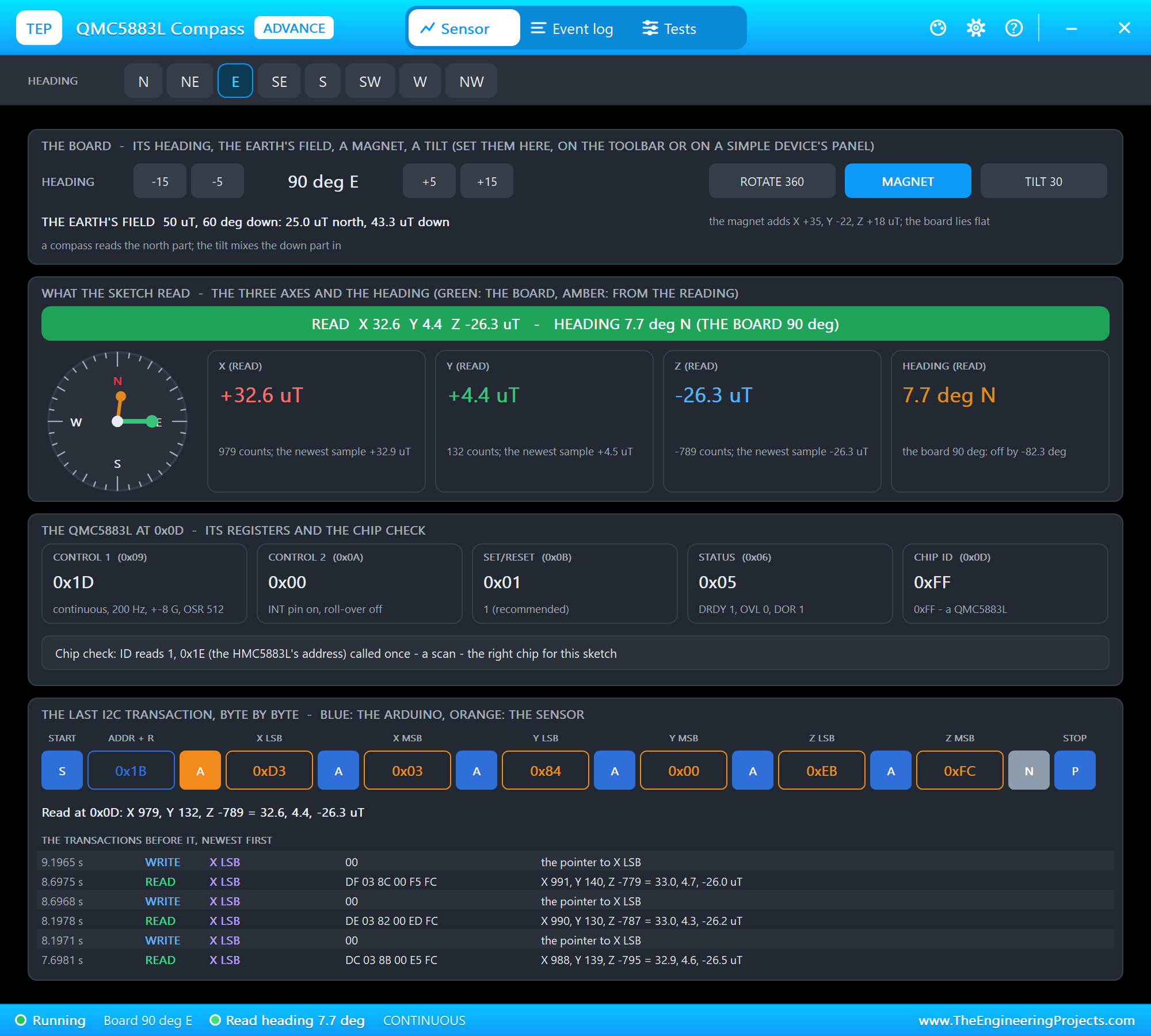
At Run, the Advance module opens its own window, QMC5883L Compass, with the look of our TEP Serial Monitor Advance for Proteus. It has three tabs, Sensor, Event log and Tests, plus Settings and Help behind the gear and question mark icons. The status bar at the bottom always shows the board's heading, the heading the sketch read and the chip's mode.
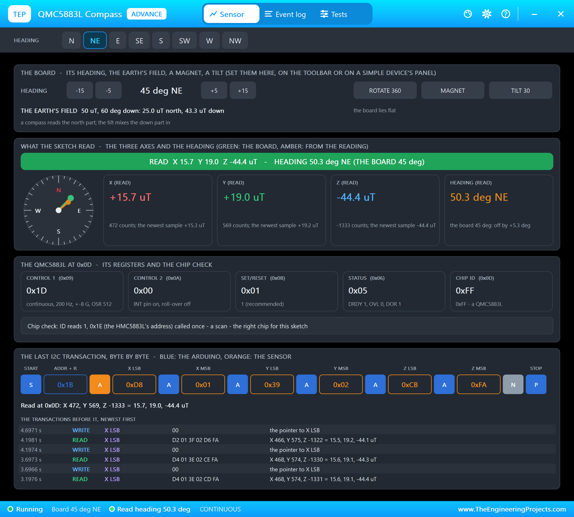
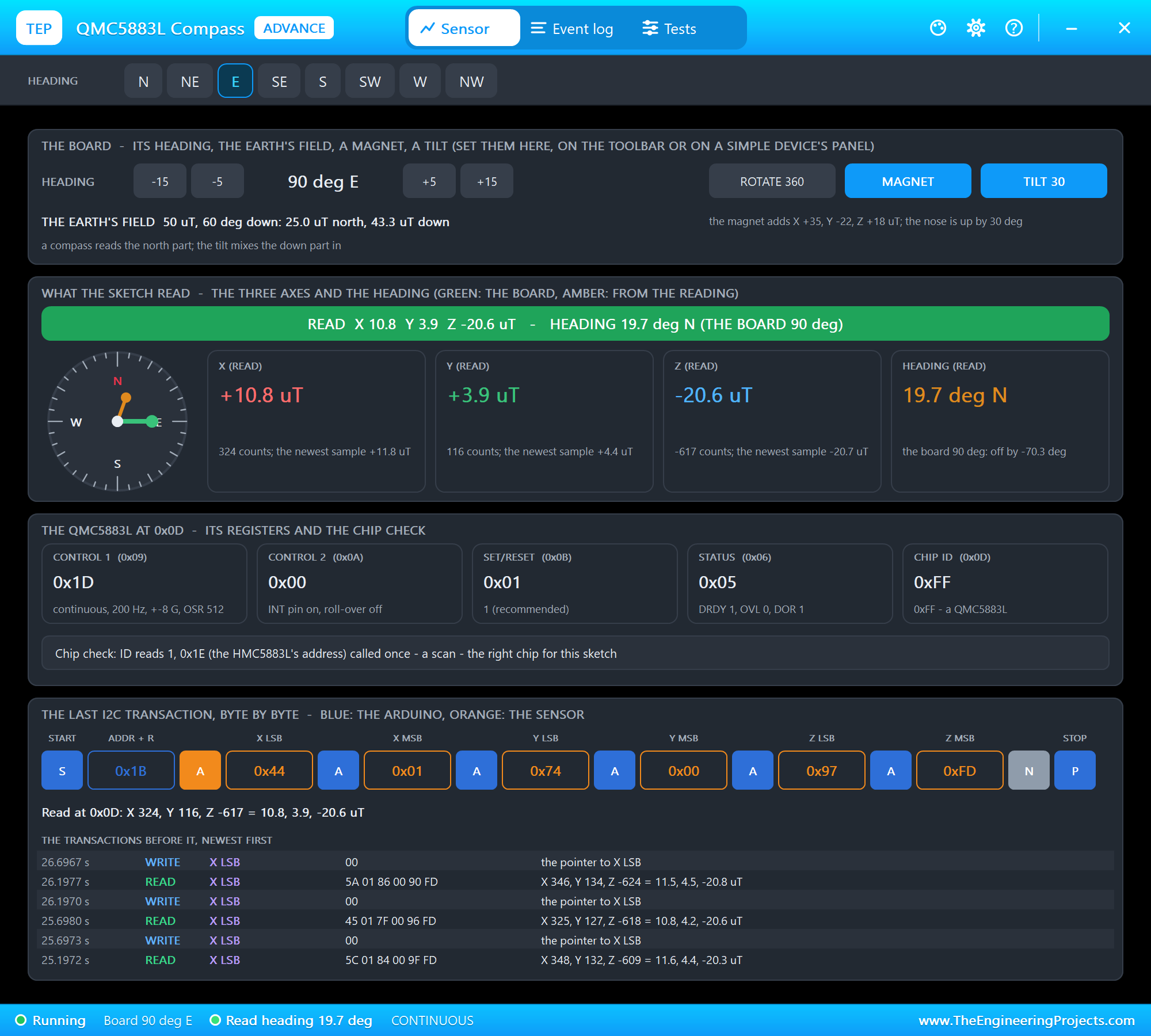
The toolbar carries the eight points. The top card is the board: the heading with -15, -5, +5 and +15 degrees, ROTATE 360, MAGNET and TILT 30, and the Earth's field split into its north and its down part. What the sketch read draws a compass rose, green for the board and amber for the heading from the reading, next to X, Y, Z and the heading with their counts. The QMC5883L at 0x0D shows the registers and the chip check; here it says that 0x1E was called once, a scan, and that this is the right chip for the sketch. The last card draws the last I2C transaction byte by byte, with the ones before it. We clicked E:
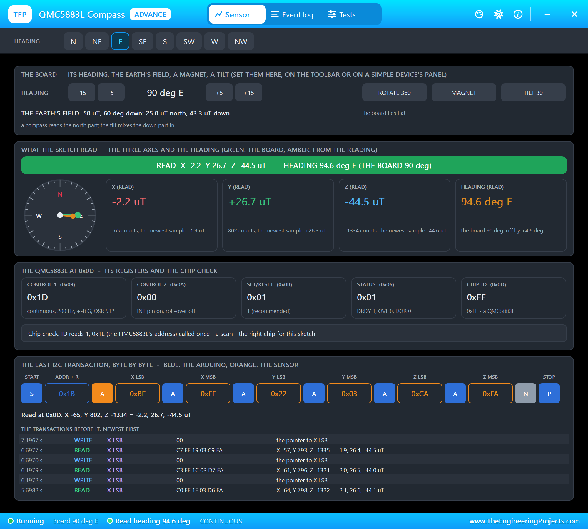
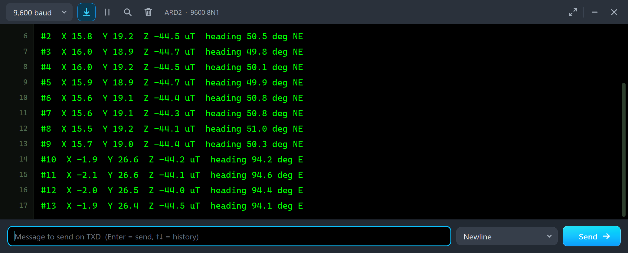
#8  X 15.5  Y 19.2  Z -44.1 uT  heading 51.0 deg NE
#9  X 15.7  Y 19.0  Z -44.4 uT  heading 50.3 deg NE
#10  X -1.9  Y 26.6  Z -44.2 uT  heading 94.2 deg E
#11  X -2.1  Y 26.6  Z -44.1 uT  heading 94.6 deg E
#12  X -2.0  Y 26.5  Z -44.0 uT  heading 94.4 deg E
About 4 degrees off: the QMC5883L's own offset, larger than the HMC5883L's. Then MAGNET:
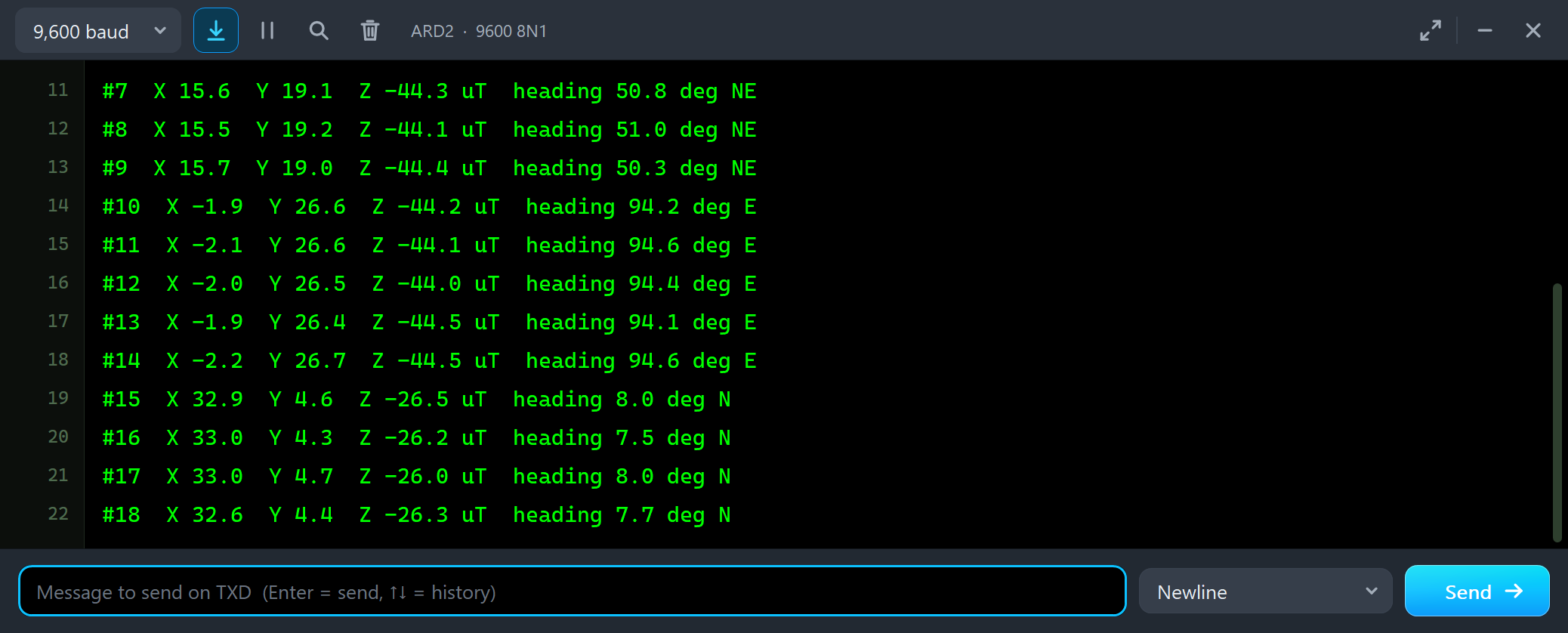
#13  X -1.9  Y 26.4  Z -44.5 uT  heading 94.1 deg E
#14  X -2.2  Y 26.7  Z -44.5 uT  heading 94.6 deg E
#15  X 32.9  Y 4.6  Z -26.5 uT  heading 8.0 deg N
#16  X 33.0  Y 4.3  Z -26.2 uT  heading 7.5 deg N
#17  X 33.0  Y 4.7  Z -26.0 uT  heading 8.0 deg N
Facing east, the magnet pulls the heading by more than 80 degrees, to 8.0 deg N. A sketch without calibration would steer your robot north while it drives east.
Calibrate It: CAL and ROTATE 360
The magnet turns with the board, so its field is the same in the board's X and Y whatever the heading. While the board turns a full circle, the Earth's part draws a circle and the magnet only shifts its centre. CAL reads the field for 10 seconds, notes the minimum and the maximum of X and Y, and keeps the centre of each as the hard-iron offset:
void calibrate() {
  Serial.println(F("CAL: turn the board a full circle now (ROTATE) - 10 s"));
  offX = 0; offY = 0;
  float minX = 1e6, maxX = -1e6, minY = 1e6, maxY = -1e6, x, y, z;
  const unsigned long start = millis();
  while (millis() - start < 10000) {
    readField(x, y, z);
    if (x < minX) minX = x;
    if (x > maxX) maxX = x;
    if (y < minY) minY = y;
    if (y > maxY) maxY = y;
    delay(20);
  }
  offX = (minX + maxX) / 2;
  offY = (minY + maxY) / 2;
  Serial.print(F("CAL: X ")); Serial.print(minX, 1); Serial.print(F(" to ")); Serial.print(maxX, 1);
  Serial.print(F(", Y ")); Serial.print(minY, 1); Serial.print(F(" to ")); Serial.print(maxY, 1);
  Serial.print(F(" uT - offsets X ")); Serial.print(offX, 1); Serial.print(F(" Y ")); Serial.print(offY, 1); Serial.println(F(" uT"));
}
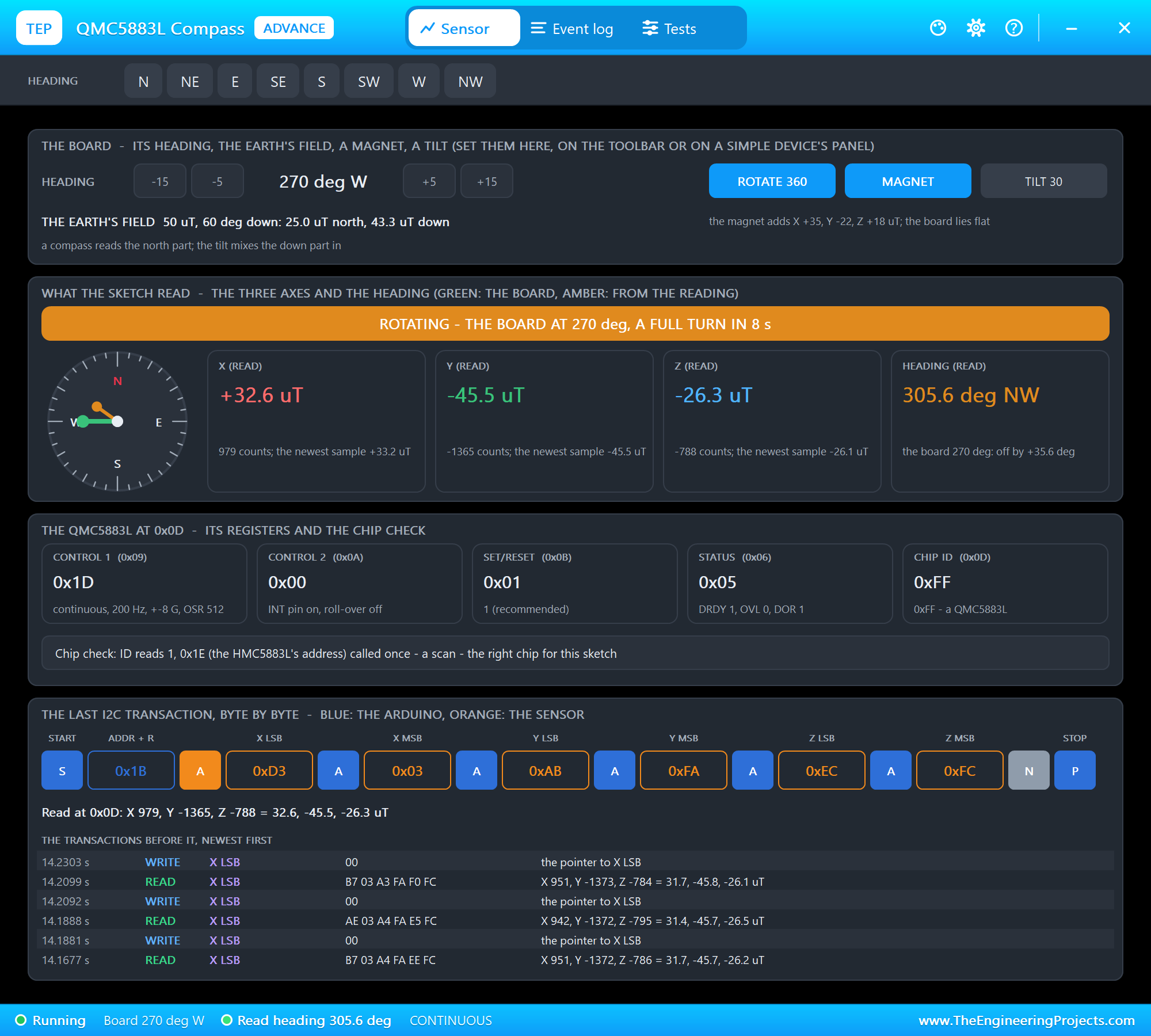
We typed CAL and clicked ROTATE 360, which turns the board a full circle in 8 seconds:
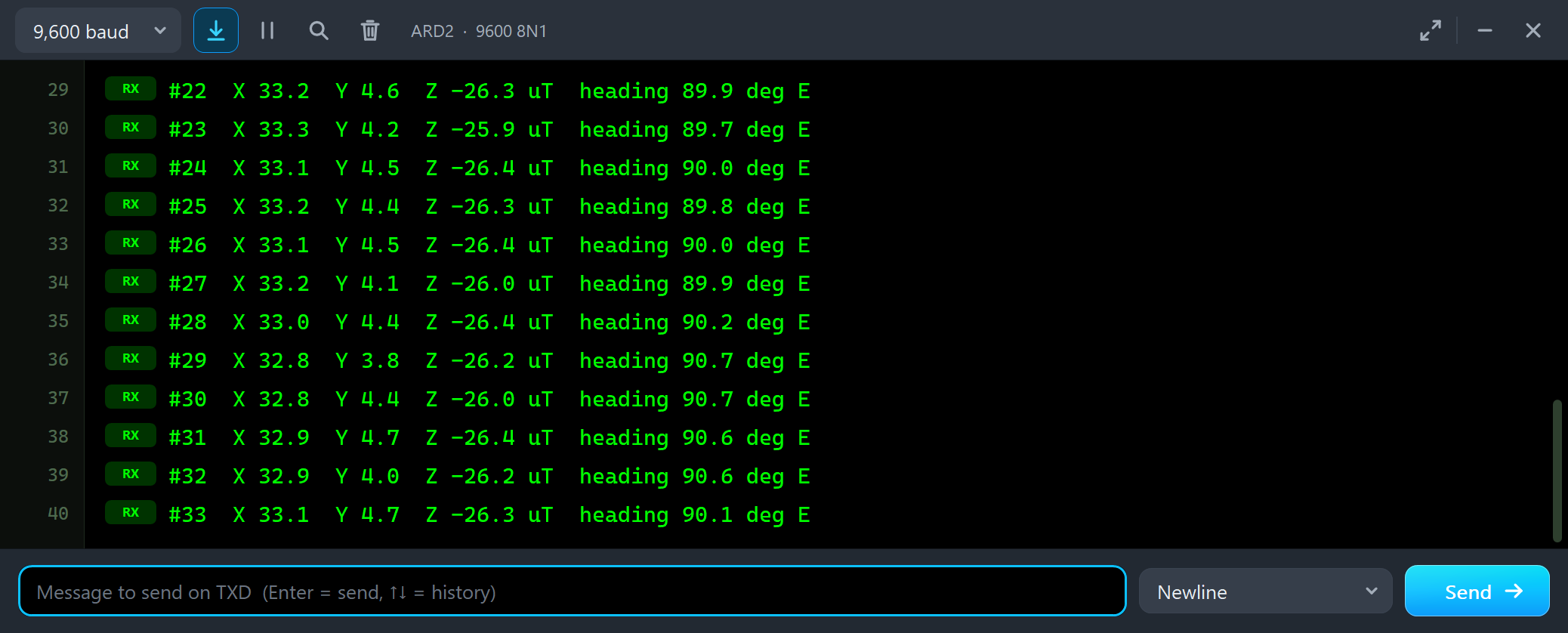
#22  X 33.2  Y 4.6  Z -26.3 uT  heading 89.9 deg E
#23  X 33.3  Y 4.2  Z -25.9 uT  heading 89.7 deg E
#24  X 33.1  Y 4.5  Z -26.4 uT  heading 90.0 deg E
#25  X 33.2  Y 4.4  Z -26.3 uT  heading 89.8 deg E
#26  X 33.1  Y 4.5  Z -26.4 uT  heading 90.0 deg E
The magnet is still on the board, the sketch still reads X about 33 and Y about 4.5 uT, but with the offsets subtracted the heading is 90.0 deg E. The offsets also took away the chip's own few degrees. The Heading & calibration tool shows the same arithmetic:
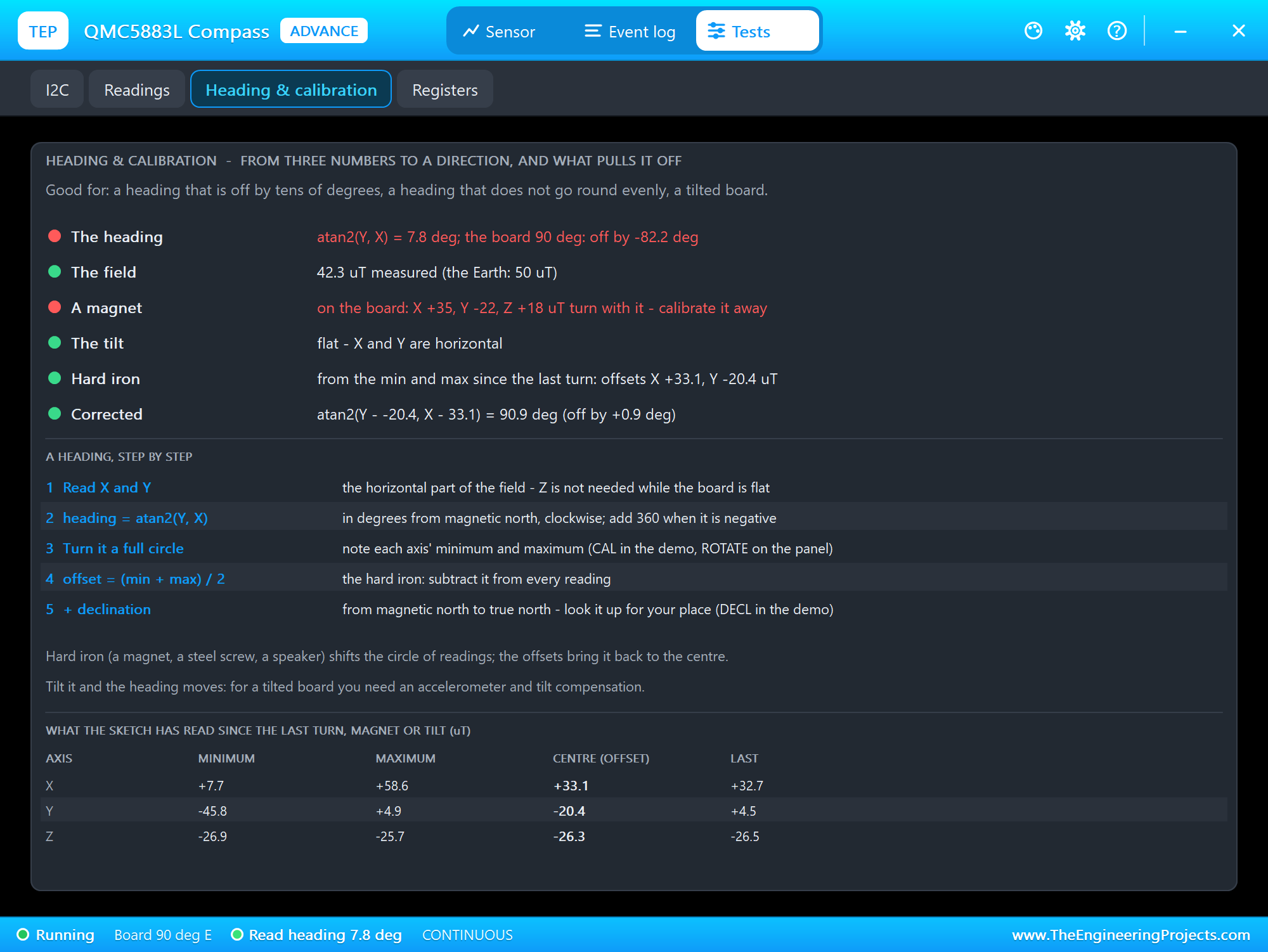
It takes the minimum and the maximum of every axis since the last turn, the magnet or the tilt, and works out the offsets: X +33.1 and Y -20.4 uT, close to the magnet's +35 and -22 plus the chip's own offset. With them, the heading from the last reading is 90.9 deg, off by less than one degree. The steps below the verdicts are the recipe for your own sketch.
Tilt the Board
Now the second thing that pulls a compass off. With the magnet still on and the offsets in use, we clicked TILT 30, the nose up by 30 degrees:
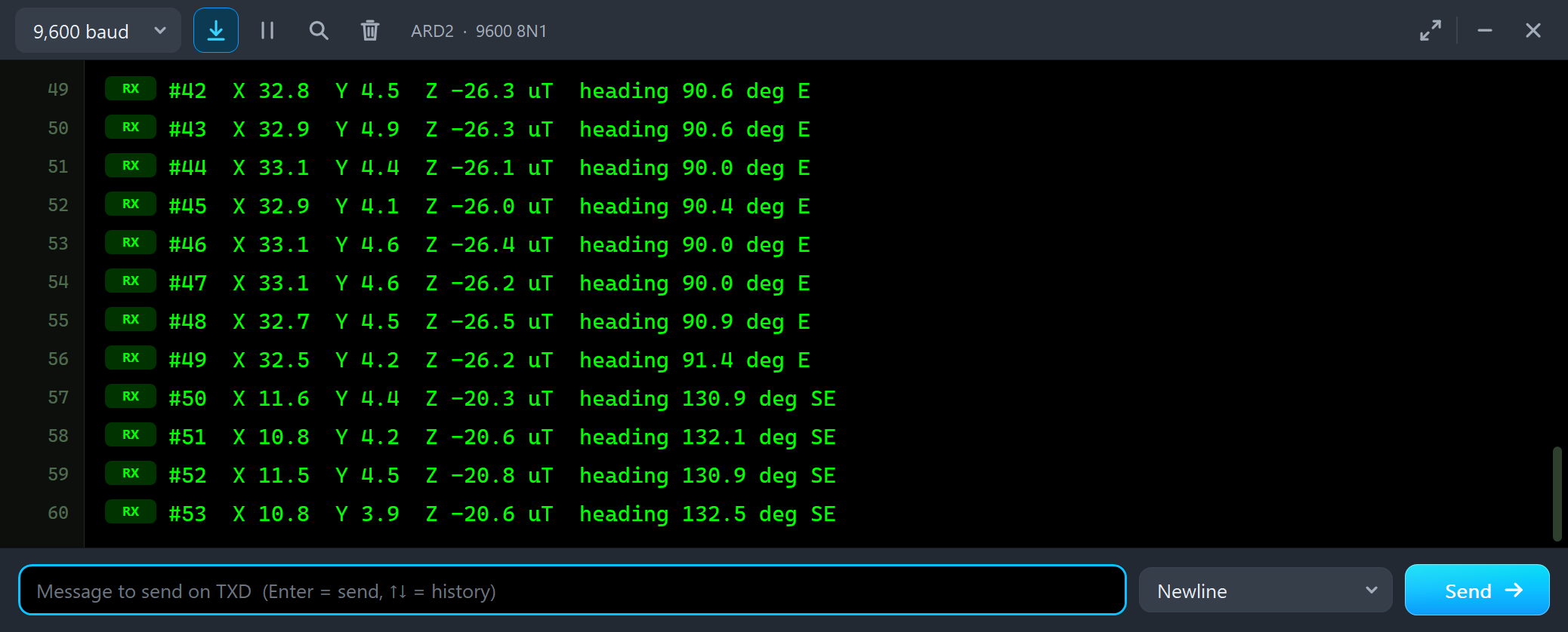
#48  X 32.7  Y 4.5  Z -26.5 uT  heading 90.9 deg E
#49  X 32.5  Y 4.2  Z -26.2 uT  heading 91.4 deg E
#50  X 11.6  Y 4.4  Z -20.3 uT  heading 130.9 deg SE
#51  X 10.8  Y 4.2  Z -20.6 uT  heading 132.1 deg SE
#52  X 11.5  Y 4.5  Z -20.8 uT  heading 130.9 deg SE
The board still points east, but the heading jumps by about 40 degrees. The Earth's field points 60 degrees down, so its downward part, 43.3 uT, is much larger than the flat part; tilt the board and a slice of it lands in X. No calibration fixes this: a compass that is not held level needs an accelerometer, as in our ADXL345 Accelerometer Library for Proteus, to measure the tilt and turn X and Y back to the horizontal.
The Trap: an HMC5883L Library on a QMC5883L Board
This is the mistake that fills the forums. The board is flat again, and we typed TRAP on node 2, which runs the Adafruit HMC5883L library's calls on the QMC5883L board:
void trap() {
  Serial.println(F("TRAP: the Adafruit HMC5883 library on this board (it talks to 0x1E only):"));
  hmc.begin();
  delay(100);
  sensors_event_t e;
  hmc.getEvent(&e);
  float h = atan2(e.magnetic.y, e.magnetic.x) * 180.0 / PI;
  if (h < 0) h += 360;
  Serial.print(F("TRAP: X ")); Serial.print(e.magnetic.x, 2);
  Serial.print(F("  Y ")); Serial.print(e.magnetic.y, 2);
  Serial.print(F("  Z ")); Serial.print(e.magnetic.z, 2);
  Serial.print(F(" uT  heading ")); Serial.println(h, 1);
  if (chip == QMC) Serial.println(F("TRAP: nobody answers 0x1E - every byte reads 0xFF, so X = Y = Z = -1 count, whatever the board does"));
}
#55  X 33.1  Y 4.1  Z -26.4 uT  heading 90.0 deg E
#56  X 33.0  Y 4.7  Z -26.5 uT  heading 90.2 deg E
#57  X 33.1  Y 4.3  Z -26.1 uT  heading 90.0 deg E
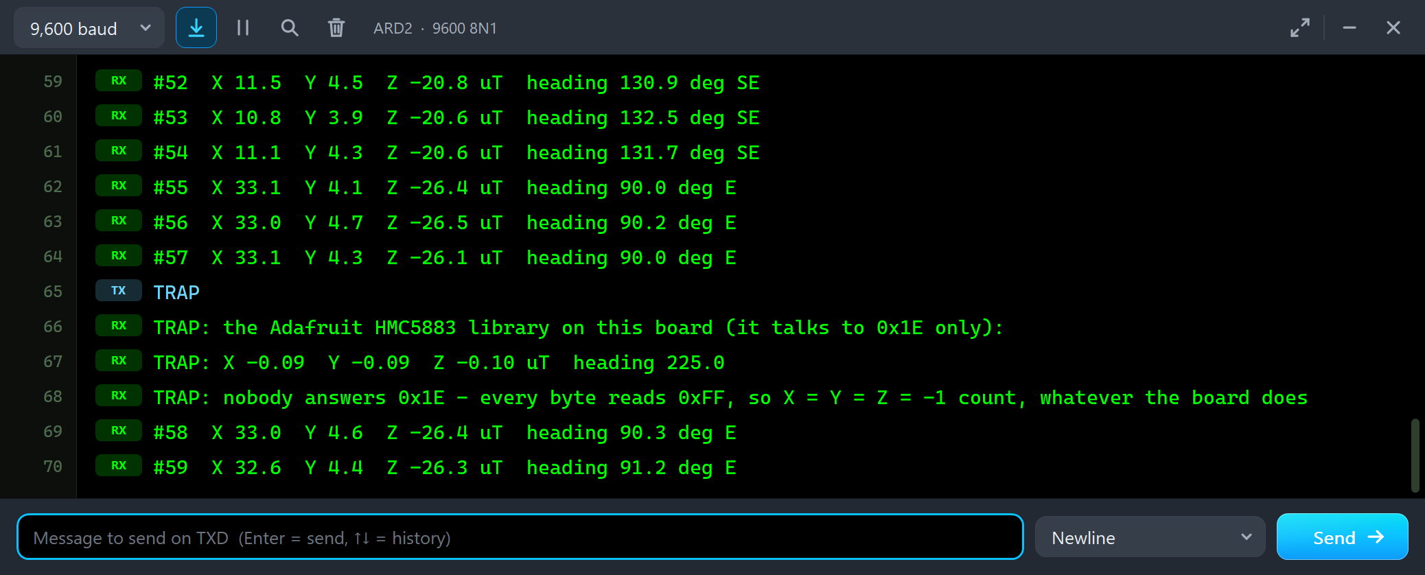
TRAP
TRAP: the Adafruit HMC5883 library on this board (it talks to 0x1E only):
TRAP: X -0.09  Y -0.09  Z -0.10 uT  heading 225.0
TRAP: nobody answers 0x1E - every byte reads 0xFF, so X = Y = Z = -1 count, whatever the board does
#58  X 33.0  Y 4.6  Z -26.4 uT  heading 90.3 deg E
begin() returned true, getEvent() returned values, and nothing complained, yet the numbers are nonsense. Nobody answers at 0x1E, so the bus floats HIGH and every byte reads 0xFF: each axis is -1 count, which the library divides by 1100 or 980, and the heading is always 225.0. Turn the board, put a magnet on it, and nothing changes. The model saw it too:
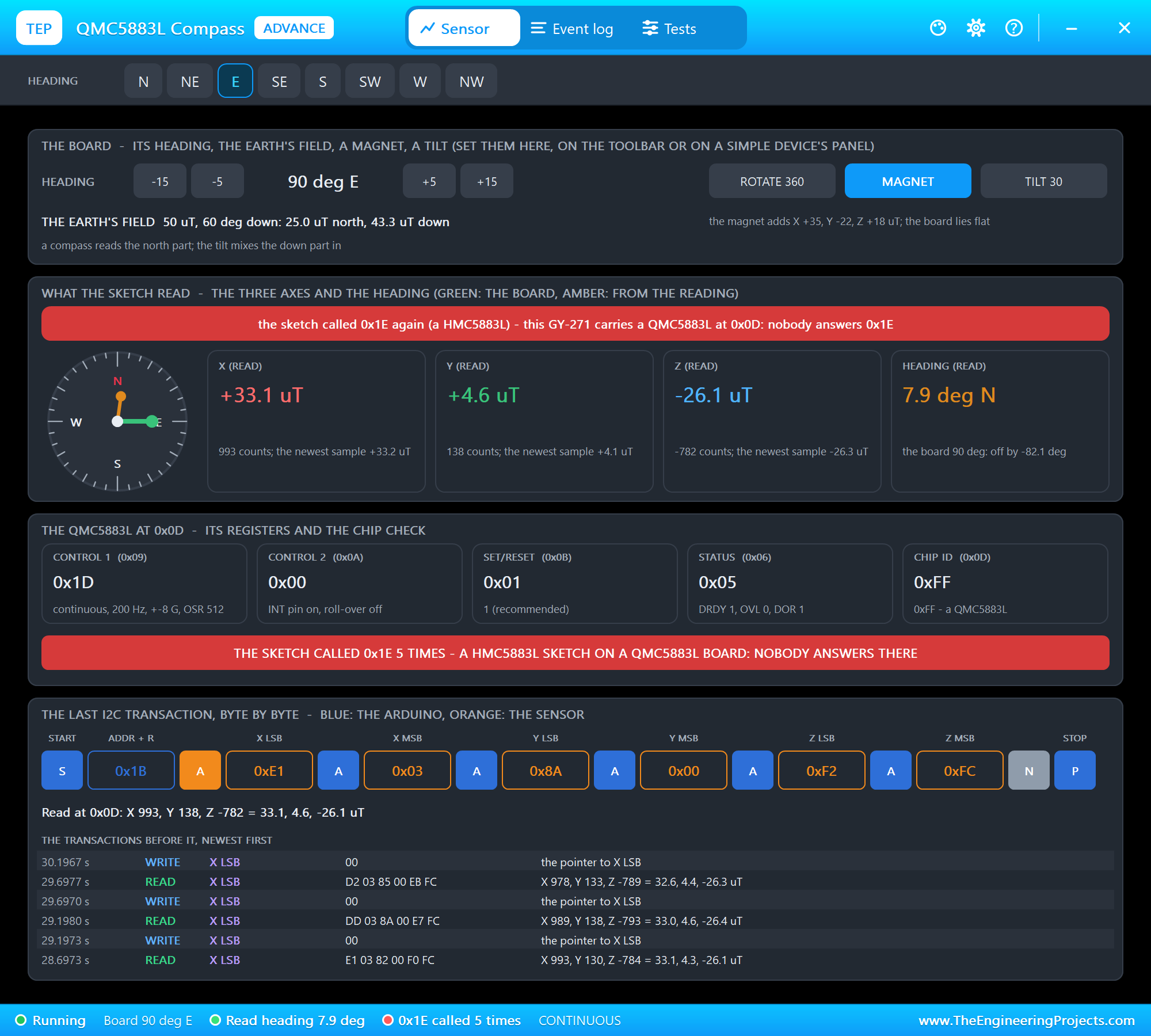
The first call to 0x1E was the demo's own scan, so it was only noted. After the second call the banners turn red, and the status bar counts the calls. In your own project this is the moment to change the library, or the board.
RAW on the QMC5883L
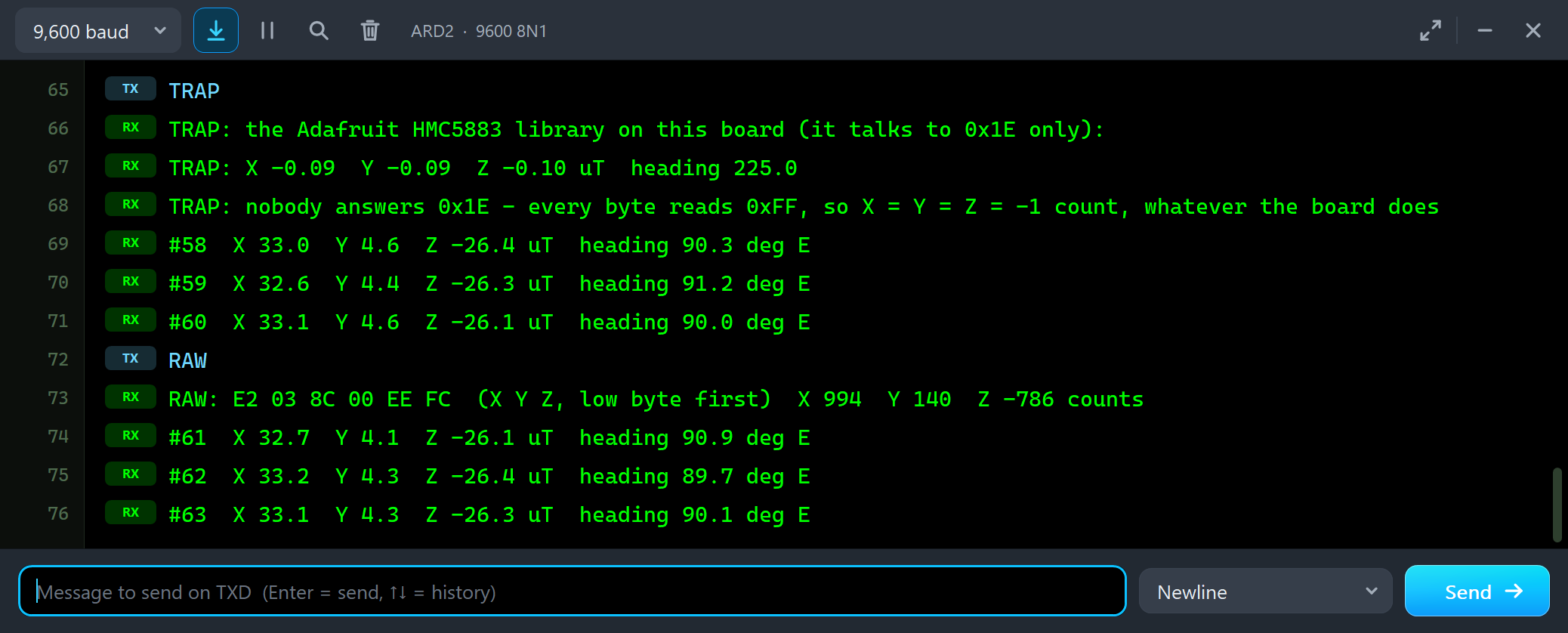
#60  X 33.1  Y 4.6  Z -26.1 uT  heading 90.0 deg E
RAW
RAW: E2 03 8C 00 EE FC  (X Y Z, low byte first)  X 994  Y 140  Z -786 counts
#61  X 32.7  Y 4.1  Z -26.1 uT  heading 90.9 deg E
The QMC5883L sends X, Y, Z in order, each low byte first: E2 03 is X = 0x03E2 = 994 counts, 8C 00 is Y = 140 and EE FC is Z = -786. Divided by 30 that is 33.1, 4.7 and -26.2 uT. Compare it with node 1: the same six bytes, two orders.
The Test Tools
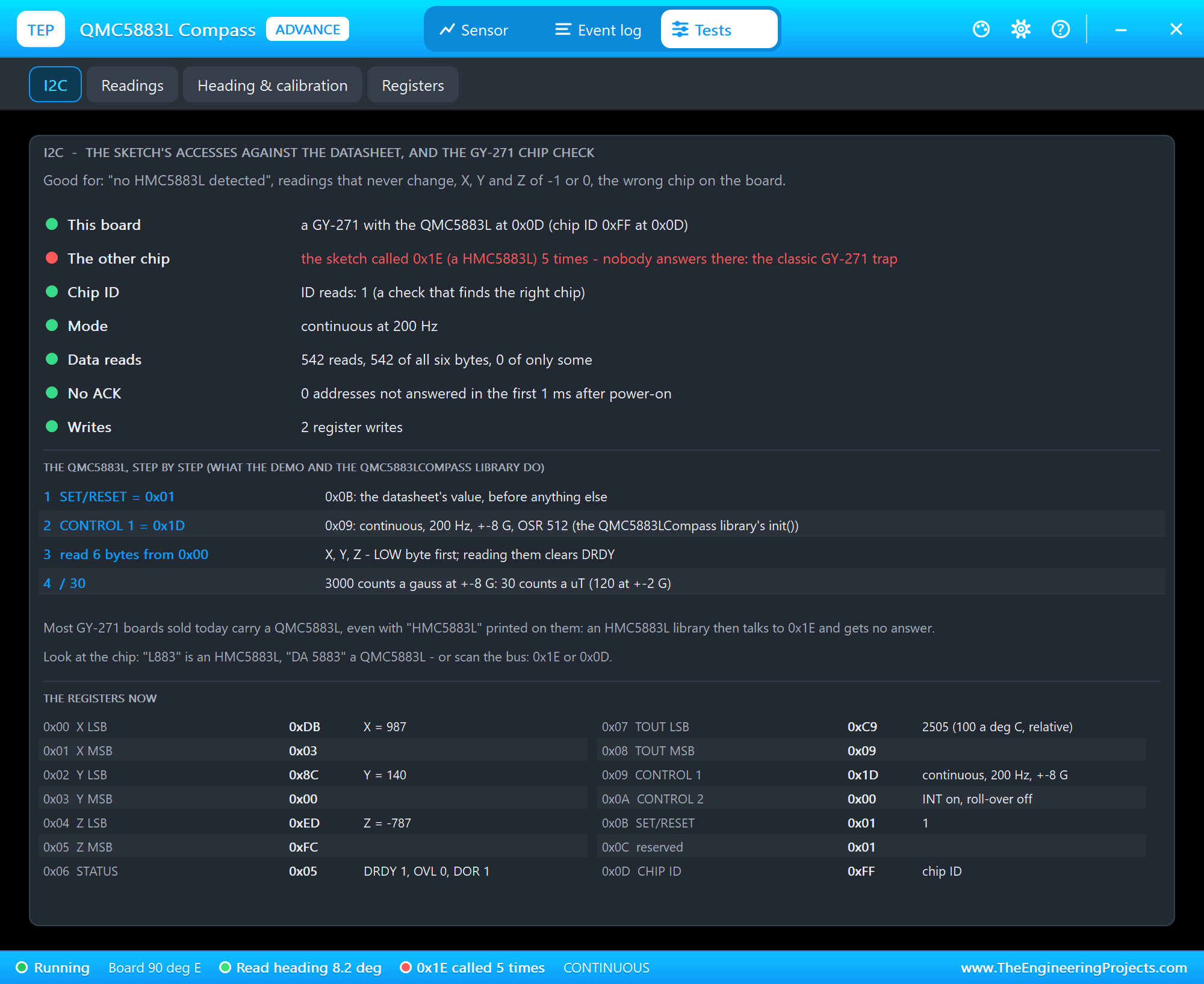
The I2C tool is the one to open for "no HMC5883L detected", readings that never change, X, Y and Z of -1 or 0, or the wrong chip on the board. It names this board and its address, counts the calls to the other chip's address, the ID reads, the data reads with all six bytes or only some, and the accesses without ACK, then shows the chip's set-up step by step and the registers now. The Readings tool lists the last 24 transactions:
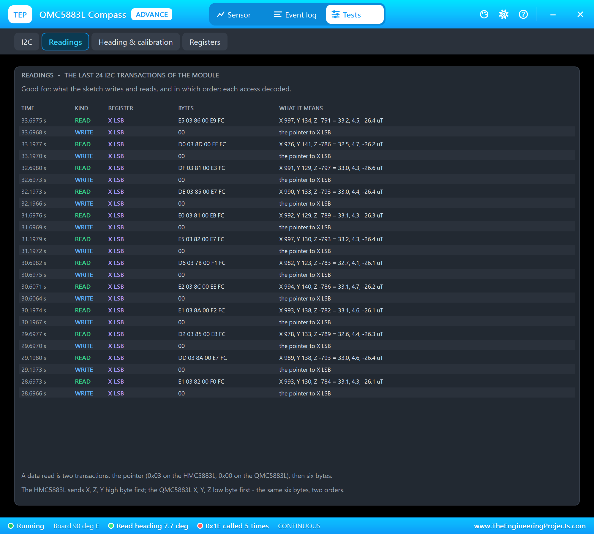
Each data read is two transactions: the pointer to the first data register, then the six bytes. The Registers tool decodes the settings:
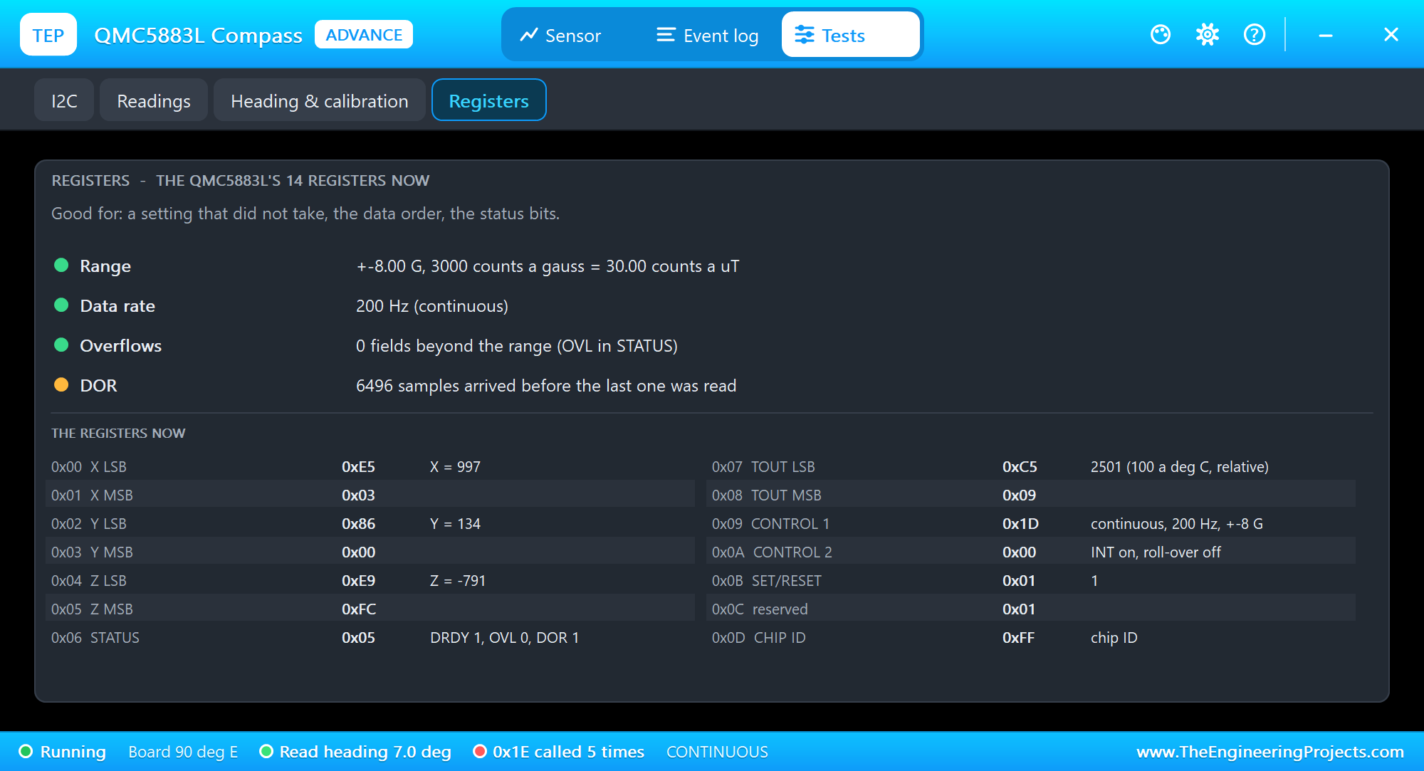
Here DOR is amber, and that is fine: the chip makes 200 samples a second and the sketch reads two, so most samples are skipped. A sketch that must not miss one reads faster, or picks a lower data rate.
The Event Log
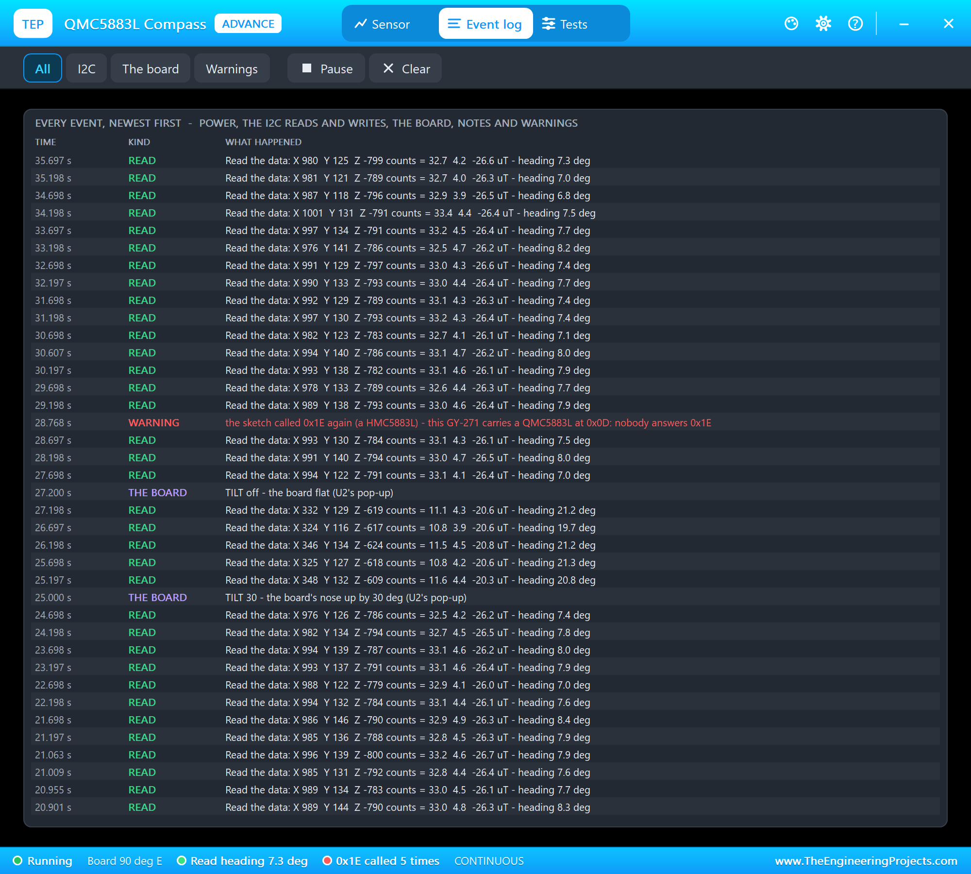
The Event log lists everything that happened, newest first: the power, the register writes, the data reads, the changes to the board with where they came from, notes and warnings. Filter it by I2C, the board or warnings, pause it, or clear it.
The Simulation Log
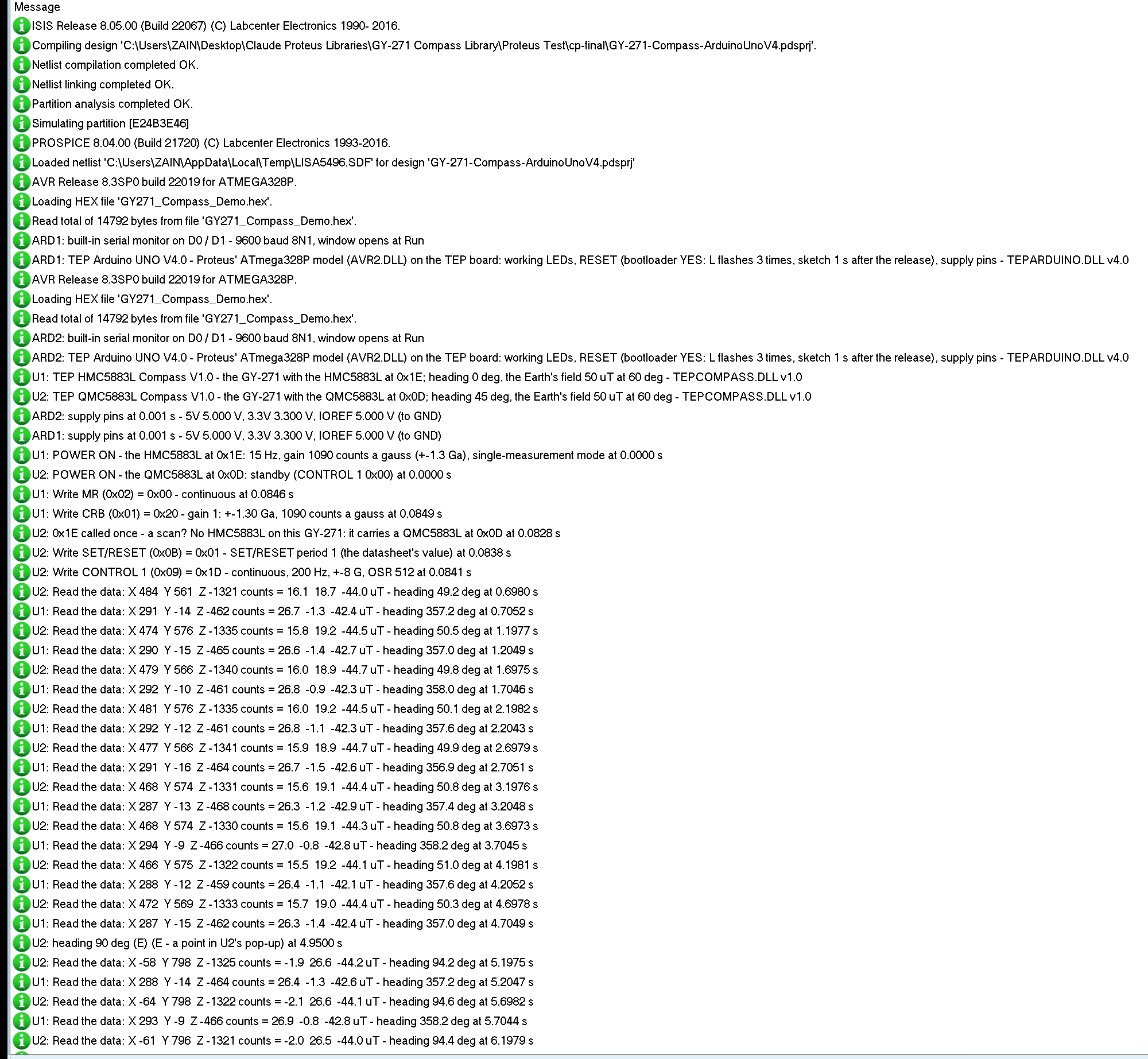
The modules also write to the simulation log of Proteus, with the exact simulation time. This part shows the start of both nodes:
U1: TEP HMC5883L Compass V1.0 - the GY-271 with the HMC5883L at 0x1E; heading 0 deg, the Earth's field 50 uT at 60 deg - TEPCOMPASS.DLL v1.0
U2: TEP QMC5883L Compass V1.0 - the GY-271 with the QMC5883L at 0x0D; heading 45 deg, the Earth's field 50 uT at 60 deg - TEPCOMPASS.DLL v1.0
U1: POWER ON - the HMC5883L at 0x1E: 15 Hz, gain 1090 counts a gauss (+-1.3 Ga), single-measurement mode at 0.0000 s
U2: POWER ON - the QMC5883L at 0x0D: standby (CONTROL 1 0x00) at 0.0000 s
U1: Write MR (0x02) = 0x00 - continuous at 0.0846 s
U1: Write CRB (0x01) = 0x20 - gain 1: +-1.30 Ga, 1090 counts a gauss at 0.0849 s
U2: 0x1E called once - a scan? No HMC5883L on this GY-271: it carries a QMC5883L at 0x0D at 0.0828 s
U2: Write SET/RESET (0x0B) = 0x01 - SET/RESET period 1 (the datasheet's value) at 0.0838 s
U2: Write CONTROL 1 (0x09) = 0x1D - continuous, 200 Hz, +-8 G, OSR 512 at 0.0841 s
U2: Read the data: X 484  Y 561  Z -1321 counts = 16.1  18.7  -44.0 uT - heading 49.2 deg at 0.6980 s
U1: Read the data: X 291  Y -14  Z -462 counts = 26.7  -1.3  -42.4 uT - heading 357.2 deg at 0.7052 s
The HMC5883L wakes up in single-measurement mode, and the Adafruit library's begin() switches it to continuous and sets the gain. U2 notes the demo's scan of 0x1E as a scan, not as a mistake, then takes the two writes of the QMC5883L's set-up. Each reading is logged with its counts, its uT and its heading.
How the Model Works
The modules are digital models. VCC and GND power them, and SCL and SDA are the I2C bus: Proteus runs every edge from the Arduino with its exact time, and the model pulls SDA low to acknowledge and to send. At its data rate the chip takes a sample of the field: the Earth's field turned into the board's axes for its heading and tilt, plus the magnet, plus the chip's own small offset and noise. The sample is scaled to the chip's range, clipped where the chip clips, and stored in its registers in its own byte order. DRDY changes at the simulation time of each new sample.
Troubleshooting
- "no compass at 0x1E or 0x0D": no power on VCC and GND, or SDA and SCL swapped or missing; the PWR LED is off or the I2C LED never flashes.
- X, Y and Z are -0.09, -0.09 and -0.10 uT and never change: an HMC5883L library on a QMC5883L board; use the QMC5883L's address 0x0D and its registers.
- The values are all 0: the chip was never started; MR = 0x00 on the HMC5883L, CONTROL 1 continuous on the QMC5883L.
- The heading is off by tens of degrees: a magnet or steel near the board, so calibrate while it turns; or the board is tilted.
- The heading jumps between about 0 and 359: that is north, where 360 and 0 meet; keep it from 0 to 360 with "plus 360 when negative".
- A value reads -4096 on the HMC5883L: the field is beyond the gain's range; pick a bigger range in CRB.
- The HMC5883L's data never changes after a partial read: LOCK; read all six data bytes.
- No part or no monitor: TEPCOMPASS.DLL or TEPARDUINO.DLL is missing from MODELS and the project folder; a closed monitor opens again with a click on the UNO's USB port.
Things to Know Before Using a Real GY-271
- Check the chip first: L883 is an HMC5883L at 0x1E, DA 5883 a QMC5883L at 0x0D; or run an I2C scanner.
- Keep it away from iron: magnets, motors, speakers, steel screws and wires that carry current all pull the heading.
- Calibrate it where it is mounted: the robot's own motors and screws are part of the hard iron.
- Hold it level, or add an accelerometer and tilt compensation.
- Add the declination of your place for true north (DECL in the demo).
Limitations of the Simulation
- Not modelled: soft iron (a field bent by nearby steel), the chips' gain errors and temperature drift, the QMC5883L's temperature offset (only relative values, as on the real chip), the HMC5883L's high-speed I2C, the clock stretching and the I2C general call. The world is simple: one fixed field, one magnet, one tilt.
- The LEDs, the badge, the panel button and the panels are TEP additions.
- The models are our own, written from the HMC5883L and QMC5883L datasheets. This library is not made or endorsed by Honeywell, QST, Adafruit, MPrograms, the makers of the GY-271 module or Labcenter.
- Licences: the demo sketch uses the Adafruit HMC5883 Unified library 1.2.4 (BSD) and Adafruit Unified Sensor 1.1.15 (Apache 2.0), which are not shipped; install them from the Library Manager. The QMC5883L part is our own code with the register values of the QMC5883LCompass library (GPL 3.0), which is not used or shipped. The demo's HEX file contains the Adafruit libraries and the Arduino AVR core 1.8.6 with LGPL-licensed code; the licence texts and the source links are in the README.
- Tested in Proteus 8.5 in October 2026 (the demo as shipped on two Arduino UNO V4.0 boards with their built-in monitors: both nodes reading from the start; W, the heading buttons, MAGNET, RAW and TRAP on node 1 with the mouse, the red X and PANEL; E, MAGNET, CAL with ROTATE 360, TILT 30, TRAP and RAW on node 2, the four tools; 71.9 s of simulation took 146 s, about 0.5 x real time with the pop-up and both monitors open). Proteus 7 is not supported.
So, that was all about the HMC5883L / QMC5883L Compass Library for Proteus V1.0. I hope the two chips, the heading and the calibration are clear now, and that your compass points the right way from the first run. If you use the GY-271 compass library in a project, please share it in the comments or in our forum, and if you have any questions, ask in the comments and I will help you out. Till the next tutorial, take care and have fun!
Comments
0