


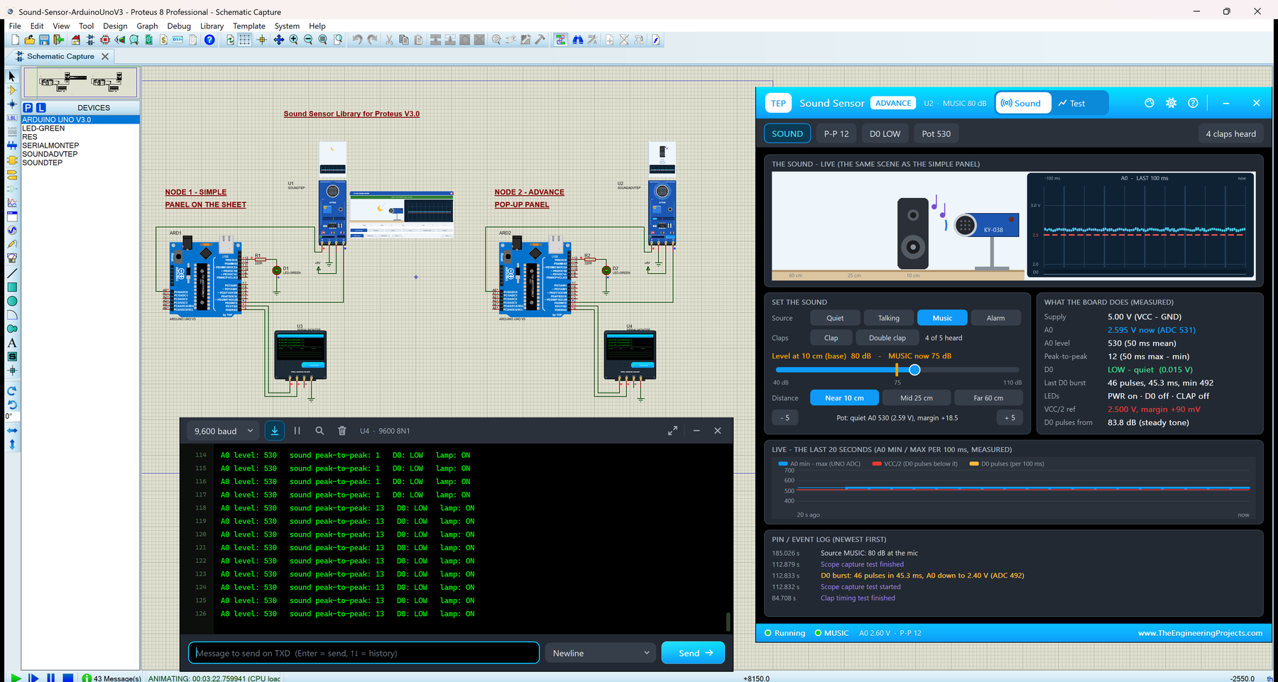
Sound Sensor Library for Proteus V3.0 (KY-038 + Arduino)


Hello friends, I hope you all are doing great. Today, I am going to share the new Sound Sensor Library for Proteus V3.0. The KY-038 is the small blue sound sensor module with a microphone, a sensitivity pot and an LM393 comparator. Its A0 output carries the microphone's sound wave, and its D0 output pulses when a sound is loud enough. With this Sound Sensor Library for Proteus, you pick the sound, its distance and the pot, and your Arduino reads A0 and D0 exactly as it would on a real board.
We shared earlier versions of a sound sensor library before; version 3.0 is a new model with its own parts and files. You get two devices: Sound Simple with a scene panel on the schematic, and Sound Advance with a pop-up window and four measured sound test tools. The demo is a clap switch on two Arduino UNOs, shown in the compact Simple interface of our TEP Serial Monitor.
NOTICE: This library is very special to our team. Our KY-038 model is a real analog part in Proteus's SPICE simulator, and every number on its panels is measured from the A0 and D0 node voltages while your Arduino runs. It took our team a lot of hard work, many test runs and many design changes. Your feedback is the fuel that keeps us going, so please tell us what you think in the comments below or in the Sound Sensor Library board of our forum. And if our free libraries help you, you can buy us a coffee. So, let's get started with the Sound Sensor Library for Proteus:
What is the KY-038 Sound Sensor?
The KY-038 is a small sound sensor module, about 35 x 15 mm, on a blue board. At one end sits an electret microphone, a silver capsule with a black mesh. The rest of the board is a simple circuit around the LM393 comparator: a blue multi-turn trimmer (the sensitivity pot, marked 104), a PWR LED, a D0 LED and a 4-pin header printed A0 G + D0. Makers use it for clap switches, noise alarms and sound-activated projects.
The KY-038 is not a sound level meter. A0 is the raw microphone signal, without an amplifier, and the board has no dB scale. It hears loud, close sounds such as a clap or an alarm clock well, and normal talking only as a small wiggle. The KY-037 is the same board with a bigger microphone.
The KY-038 at a Glance
| Feature | Value |
|---|---|
| Microphone | Electret capsule |
| Comparator | LM393, drives D0 |
| Outputs | A0: analog, the microphone signal on a DC level; D0: digital, pulses on a loud sound |
| Sensitivity | A blue multi-turn trimmer pot (marked 104) |
| LEDs on the real board | PWR and D0 (both red) |
| Header | A0, G, +, D0 (four pins) |
| Supply | 3.3 to 5 V |
| Board | About 35 x 15 mm, portrait |
| Typical uses | Clap switches, noise detection, sound triggers |
Sound Sensor Terms You Will See in This Article
| Term | Meaning |
|---|---|
| A0 | The analog output: the microphone's sound wave on a DC level |
| D0 | The digital output of the LM393: HIGH while the wave dips below VCC/2 |
| ADC count | What analogRead() returns: 0 to 1023 at 5 V |
| Quiet level | A0 in a quiet room, set by the pot (ADC 530 = 2.59 V by default) |
| VCC/2 | The comparator's reference: 2.50 V at a 5 V supply |
| Margin | How far the quiet level sits above VCC/2 (18.5 counts = 90 mV by default) |
| Peak-to-peak (P-P) | How far A0 swings: the highest minus the lowest reading, in ADC counts |
| dB | The sound level in decibels; in our model, 6 dB louder = twice the swing |
| Burst | The train of D0 pulses that one loud sound makes |
| Debounce | Ignoring D0 for a while after the first pulse, so one clap counts once |
How the KY-038 Turns Sound Into A0 and D0
A0: the Sound Wave on a DC Level
The microphone signal is a wave on a DC level that the pot sets. In a quiet room A0 sits at about 2.59 V, which an Arduino UNO reads as 530; a sound moves it up and down around that level. So one analogRead() tells you little: read A0 for about 50 ms and take the peak-to-peak, as our demo does. A clap 10 cm away swings A0 by more than 100 counts; normal talking by only a few.
D0: Pulses, Not a Level
The LM393 compares A0 with half the supply, VCC/2 (2.50 V at 5 V). D0 goes HIGH while the wave dips below VCC/2 and LOW again when it comes back above. The board has no hysteresis, so during a loud sound D0 does not stay HIGH: it pulses, once per cycle of the sound, and the D0 LED flickers. A single clap close by gives a burst of 9 short pulses in about 18 ms. That is why a clap-switch sketch takes the first pulse as "a clap" and then ignores D0 for a while.
The Pot Sets the Sensitivity
The pot sets the quiet level of A0. Its distance above VCC/2, the margin, is the swing a sound needs before its dips reach VCC/2: by default 18.5 counts (about 90 mV). Turn the pot towards VCC/2 (POT - on our panel) and a quieter sound trips D0. Turn it too far, below VCC/2, and D0 is HIGH all the time: the well-known "D0 LED always on" problem.
Louder Means a Bigger Swing: the dB Rule in Our Model
Our model turns the sound level at the microphone into the size of the swing at A0:
peak swing (ADC counts) = 120 x 10^((dB - 100) / 20)
So 100 dB gives a peak of 120 counts (240 peak-to-peak), and every 6 dB louder doubles the swing. D0 starts to pulse when the peak is larger than the margin. With 18.5 counts, that is at 100 + 20 log(18.5 / 120) = 83.8 dB for a steady tone. The dB values are typical sound levels, not a calibration: no data sheet gives the board's dB scale.
The Sounds in Our Scene
| Sound | Level at 10 cm | What it is | With the default pot |
|---|---|---|---|
| Quiet room | 35 dB | Silence, with a 1-count noise floor | D0 stays LOW |
| Talking | 68 dB | Phrases of syllables, 150 to 600 Hz | Never trips D0 |
| Music | 80 dB | A chord with a beat | Below the threshold; needs POT 515 or a higher level |
| Alarm | 90 dB | 880 Hz beeps, 0.25 s on and 0.25 s off | Trips D0 at NEAR only |
| Clap | 100 dB | An 80 ms burst of 410 to 1230 Hz | Heard at NEAR and MID, not at FAR |
| Double clap | 100 dB | Two claps 0.35 s apart | As the clap |
The distance follows the inverse distance law: MID 25 cm is 8 dB and FAR 60 cm 16 dB quieter than NEAR 10 cm. A clap at FAR is too quiet for the default pot; click POT - three times (quiet level 515) and it is heard. In short: the KY-038 hears claps and alarms close by, not speech across the room.
What's New in Sound Sensor Library for Proteus V3.0
TEP published earlier versions of a sound sensor library for Proteus. Version 3.0 is a new model with its own parts and files (TEPSOUND.LIB and TEPSOUND.DLL). Here is what it brings:
- A real analog part: A0 (the sound wave, 4.7 k output resistance) and D0 (the LM393's open collector with a 10 k pull-up) are nodes of Proteus's SPICE simulator.
- Two devices: Sound Simple (
SOUNDTEP) with the scene panel on the sheet, and Sound Advance (SOUNDADVTEP) with a pop-up window. - A live board with sound rings, a SOUND window, a CLAP LED and a SOUND LEVEL bar (TEP additions).
- Everything shown is measured from the A0 and D0 node voltages of the running circuit.
- Six sounds, three distances and the pot, plus a level slider, an event log and a 20-second chart on the Advance.
- Four measured test tools: Level sweep, D0 threshold, Clap timing and Scope capture.
- A two-UNO clap switch demo with the TEP Serial Monitor and its own commands.
- A light package: about 1.47 MB, without the C++ source code.
Sound Sensor Library for Proteus: Simple vs Advance
Both devices run the same model with the same sound, distance and pot properties; only the panel differs:
| Feature | Simple | Advance |
|---|---|---|
| Full KY-038 model (A0 sound wave, D0 pulses, the pot, six sounds, three distances) | ✔ | ✔ |
| Blue KY-038 board: sound rings, SOUND window, PWR / CLAP / D0 LEDs, SOUND LEVEL bar | ✔ | ✔ |
| Scene panel on the schematic (scene, 100 ms scope, readouts, buttons) | ✔ | ✘ |
| Pop-up window you can move, resize and minimise | ✘ | ✔ |
| Sound page: level slider 40 to 110 dB, the board's measured values, 20 s chart, pin / event log | ✘ | ✔ |
| Level sweep, D0 threshold, Clap timing and Scope capture | ✘ | ✔ |
| TEP Dark / Light theme, text size, Help page with Copy diagnostics | ✘ | ✔ |
| PANEL property (the panel open or closed at the start) | ✔ | ✘ |
Choose Simple to keep the scene beside your circuit, and Advance when your sheet is full or you want hard numbers about your sketch. The demo has one of each.
Download Sound Sensor Library for Proteus
Click the button below to download Sound-Sensor-Library-for-Proteus-v3.0.zip (about 1.47 MB, without the C++ source code):
Sound Sensor Library for Proteus V3.0- README.txt: a detailed guide to the files, the wiring, the model, the test tools and real hardware.
- Proteus Library Files:
TEPSOUND.LIB(both devices),TEPSERIALMON.LIBand our Arduino UNO libraryArduinoV3TEP.LIB/ArduinoV3TEP.IDX. - Proteus Model Files:
TEPSOUND.DLLandTEPSERIALMON.DLL. - Proteus Simulation:
Sound-Sensor-ArduinoUnoV3.pdsprj,Clap_Switch.hex(both UNOs run it) and copies of both DLLs. - Arduino Code:
Clap_Switch.ino, the demo sketch. It needs no extra Arduino library.
No Proteus yet? Read How to Download and Install Proteus 7 and 8. New to libraries? Follow How to Install a New Library in Proteus.
How to Install Sound Sensor Library for Proteus
- Close Proteus and extract the whole zip file.
- Copy the four files from Proteus Library Files into the LIBRARY folder, usually
C:\Program Files (x86)\Labcenter Electronics\Proteus 8 Professional\LIBRARY(on some PCsC:\ProgramData\Labcenter Electronics\Proteus 8 Professional\LIBRARY; use the folder that already holds Proteus's own .LIB files). - Copy
TEPSOUND.DLLandTEPSERIALMON.DLLinto the MODELS folder. - If a
TEPSOUND.IDXis in the LIBRARY folder, delete it. - Start Proteus, press P and search for Sound. You get the Simple and the Advance device (category Sensors > Sound).
Tested in Proteus 8.5. Proteus 7 is not supported. The demo project runs as it is when Clap_Switch.hex and the two DLLs stay beside it.
The KY-038 Board in Proteus
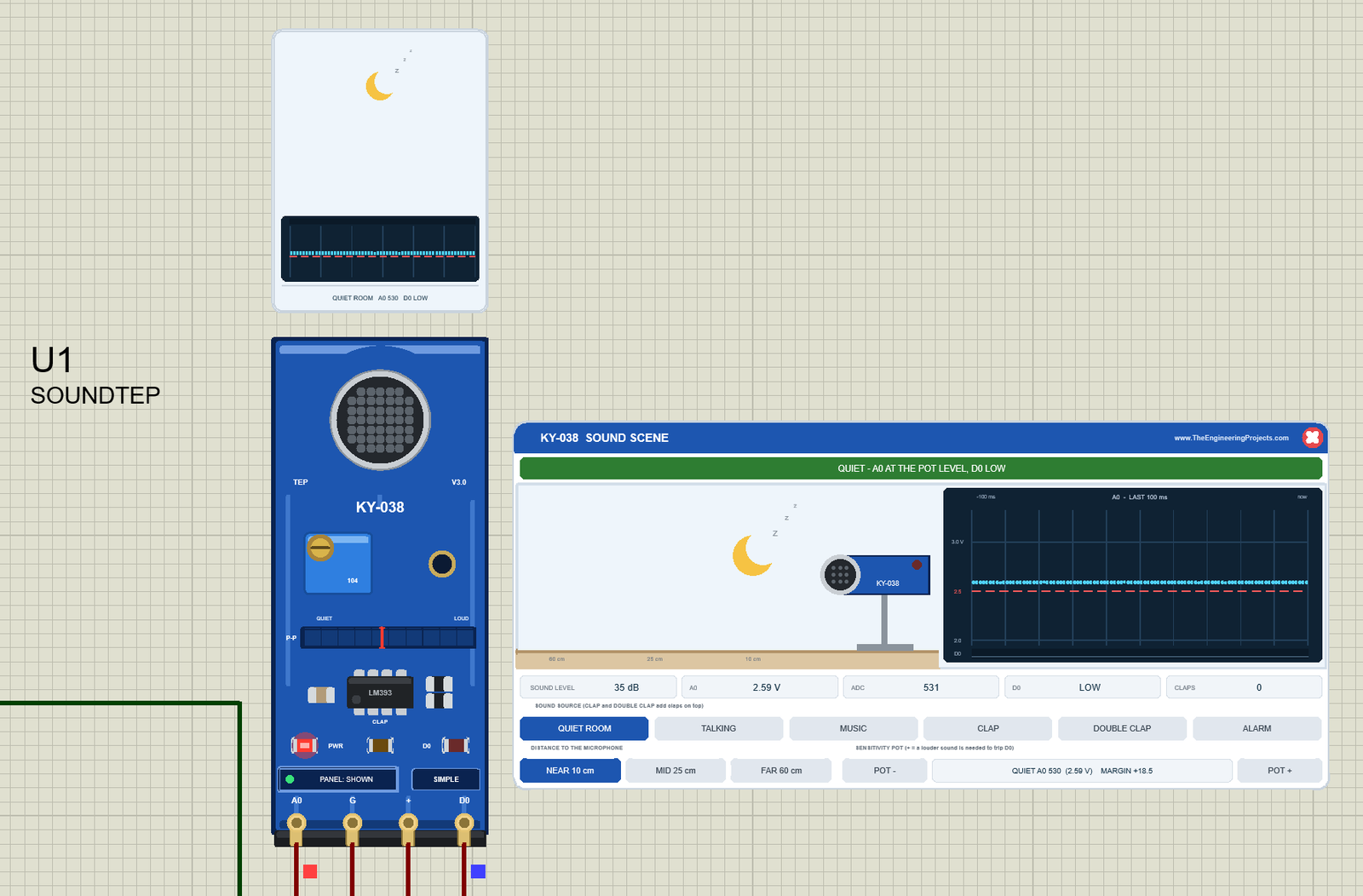
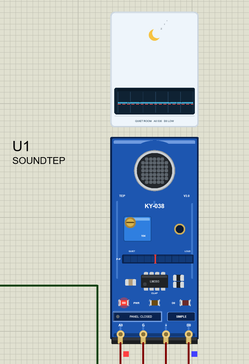
We drew the sensor as a clean TEP board in the blue of the real module and in its real portrait shape: the silver microphone with its black mesh at the top, the "KY-038" print, the blue trimmer marked 104 with its brass screw, a mounting hole, the LM393, the LEDs and the header A0 G + D0. While the simulation runs, the screw turns with the pot. Here is U1, the Simple device, in the quiet room, with its scene panel beside it:
The SOUND Window and the Sound Rings
Above the board, the SOUND window shows what the microphone hears: the source (a moon, a person talking, a loudspeaker, an alarm clock or clapping hands), its sound waves and a measured 60 ms mini scope of A0, with a summary line, here "QUIET ROOM A0 530 D0 LOW". The sound rings around the microphone turn blue for a sound below the trip level, orange while D0 pulses, and red for a clap that was heard.
Pinout
The four pins keep the order of the real header, A0 G + D0:
| Pin | Name in Proteus | What it does | Demo connection |
|---|---|---|---|
| A0 | A0 | Analog output: the microphone signal on the quiet level | Arduino A0 |
| G | GND | Ground | GND |
| + | VCC | Power, 3.3 to 5 V | +5V terminal |
| D0 | D0 | Digital output: HIGH pulses while the wave dips below VCC/2 | Arduino D2 |
LEDs and Indicators
| Indicator | What it shows |
|---|---|
| PWR LED (red) | Lit while the board has power |
| D0 LED (red) | Lit while D0 is HIGH: it flickers with the pulses, and stays on when the pot is turned too far |
| CLAP LED | Lit for 0.3 s after a clap that tripped D0 |
| SOUND LEVEL bar (P-P) | The peak-to-peak of A0 over the last 50 ms in 10 segments from QUIET to LOUD, each segment for twice the swing of the one before, with the pot's trip mark in red |
| Sound rings | Blue: a sound below the trip level; orange: D0 pulses; red: a clap that was heard |
| SOUND window | The source, its waves, a 60 ms mini scope of A0 and a summary line |
| PANEL / OPEN PANEL, SIMPLE / ADVANCE | The panel button and the device badge |
The PWR and D0 LEDs are the real module's own. The CLAP LED, the SOUND LEVEL bar, the sound rings and the SOUND window are TEP additions; the real board has none of them.
Component Properties
| Property | Meaning | Default |
|---|---|---|
| SOURCE | The sound at the start: QUIET, TALKING, MUSIC or ALARM | QUIET |
| DISTANCE | NEAR, MID or FAR, or a distance in cm (below 17 is NEAR, below 40 is MID, else FAR) | NEAR |
| POT | The quiet A0 level in ADC counts, 490 to 600 | 530 |
| PANEL | Simple only: the panel at the start, OPEN or CLOSED | OPEN |
Every Run starts again from these properties; the panel's clicks last until the simulation stops. The panel style comes from the device (Simple or Advance), not from a property.
Sound Simple: The Scene Panel on the Sheet
Beside the Simple board sits the KY-038 SOUND SCENE panel (on the right of the image above):
| Part | What it does |
|---|---|
| Header, red X | KY-038 SOUND SCENE; the X closes the panel |
| Banner | What the board does now: QUIET, SOUND BELOW THE THRESHOLD, SOUND DETECTED, CLAP!, POT TOO FAR or NO POWER |
| Scene | The source, its sound waves and a small KY-038 on a stand, on a floor with a 60 / 25 / 10 cm ruler |
| Scope "A0 - LAST 100 ms" | The min and max of the A0 node in every millisecond, as Proteus solved it, with the red VCC/2 line and a D0 lane |
| Readouts | SOUND LEVEL, A0, ADC, D0 and CLAPS |
| SOUND SOURCE row | QUIET ROOM, TALKING, MUSIC, CLAP, DOUBLE CLAP and ALARM; CLAP and DOUBLE CLAP add claps on top of the source |
| DISTANCE row | NEAR 10 cm, MID 25 cm and FAR 60 cm |
| SENSITIVITY POT | POT - and POT + in steps of 5, with the quiet level and the margin between them |
In the start image, the green banner reads QUIET - A0 AT THE POT LEVEL, D0 LOW, and the pot box says QUIET A0 530 (2.59 V) MARGIN +18.5. The scope shows the real A0 node, exactly what your Arduino samples. The ADC readout is the UNO's conversion of A0 at this moment (531), while the sketch's 50 ms mean says 530.
MUSIC: a Sound Below the Threshold
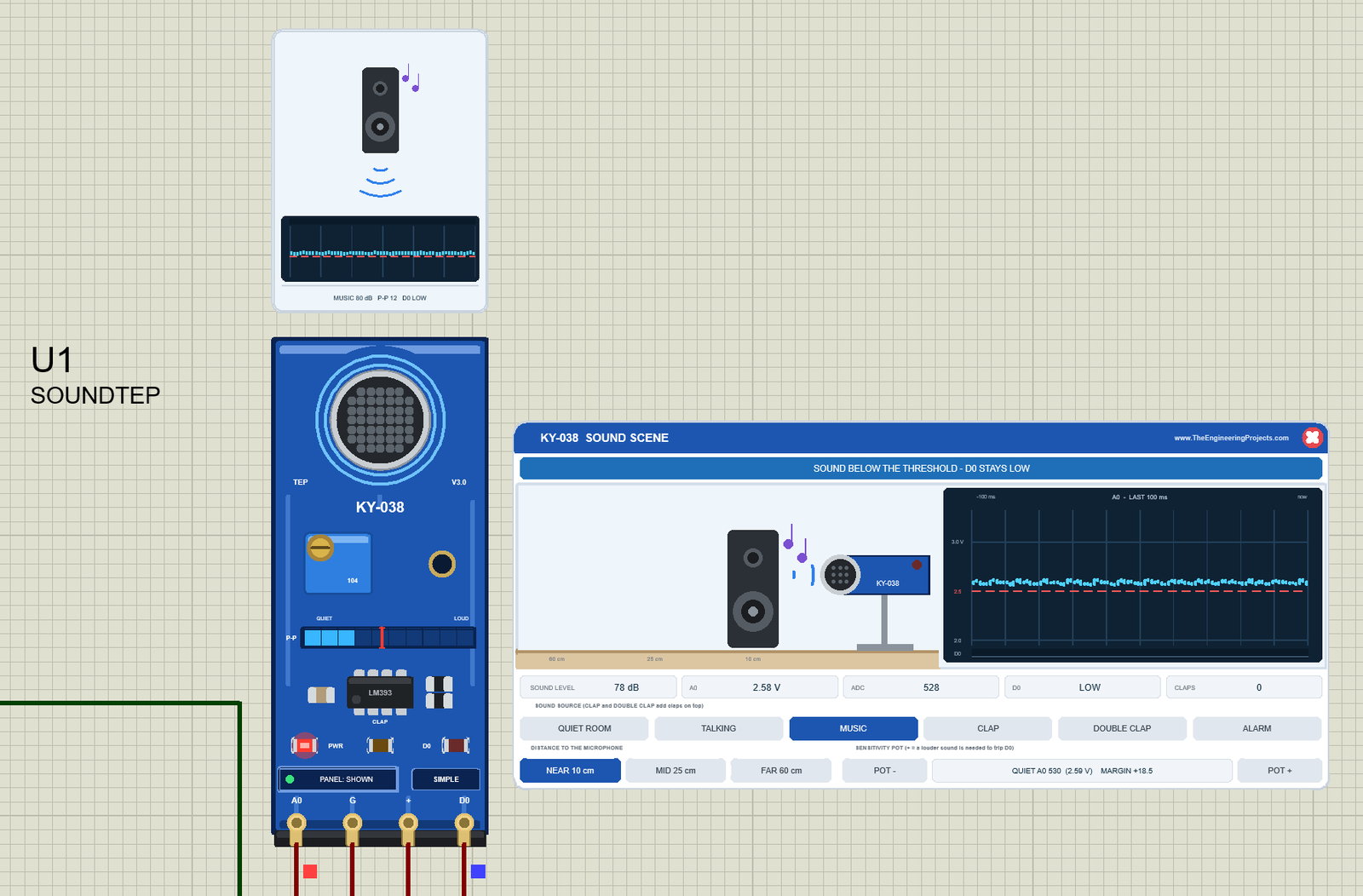
Click MUSIC: a loudspeaker plays a chord with a beat, the rings turn blue, and three segments of the SOUND LEVEL bar light, below the red trip mark. The banner says SOUND BELOW THE THRESHOLD - D0 STAYS LOW: on the scope, the music is a small wave whose dips never reach the red VCC/2 line. The window shows a peak-to-peak of 12 counts; the SOUND LEVEL readout shows the loudest level of the last 100 ms, 78 dB. Your Arduino sees the swing on A0, but D0 never reacts; click POT - three times and it does.
ALARM: D0 Pulses With Every Beep
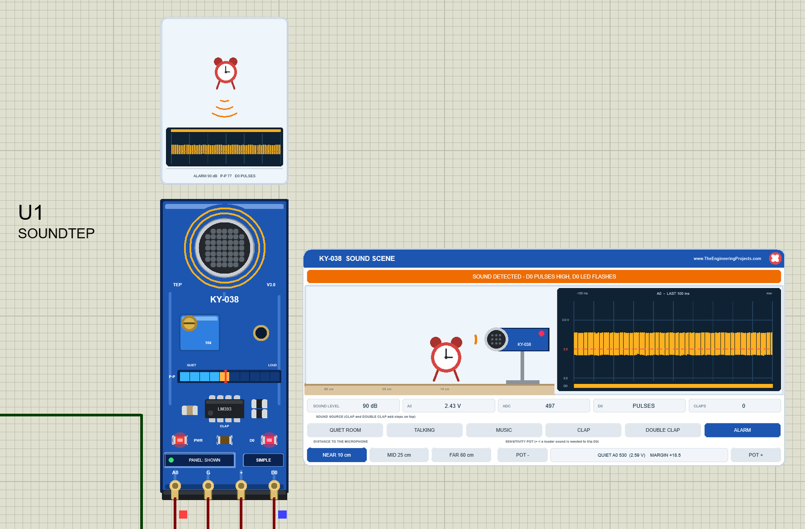
Click ALARM: an alarm clock beeps at 880 Hz, a quarter second on and a quarter second off. At 90 dB the swing is 77 counts peak-to-peak, its dips go below VCC/2, and the banner turns orange: SOUND DETECTED - D0 PULSES HIGH, D0 LED FLASHES. The rings turn orange, the D0 LED lights, five segments of the bar light (the one past the trip mark in orange) and the D0 readout says PULSES. The scope shows a dense band of the wave across the red line, with the D0 lane orange under it.
CLAPS stays 0, because the panel counts only claps. Your sketch cannot tell the difference: every beep makes a burst of D0 pulses, just like a clap, so the demo toggles its lamp with every second beep, as the results below show.
Closing the Panel
Click the red X: the board button says PANEL: CLOSED, its dot turns grey, and the sensor keeps running. Click PANEL to bring the panel back. Here, U1 is back in the quiet room:
Sound Advance: The Pop-Up Sound Window
The Advance device keeps only the board on the schematic. Here is U2:
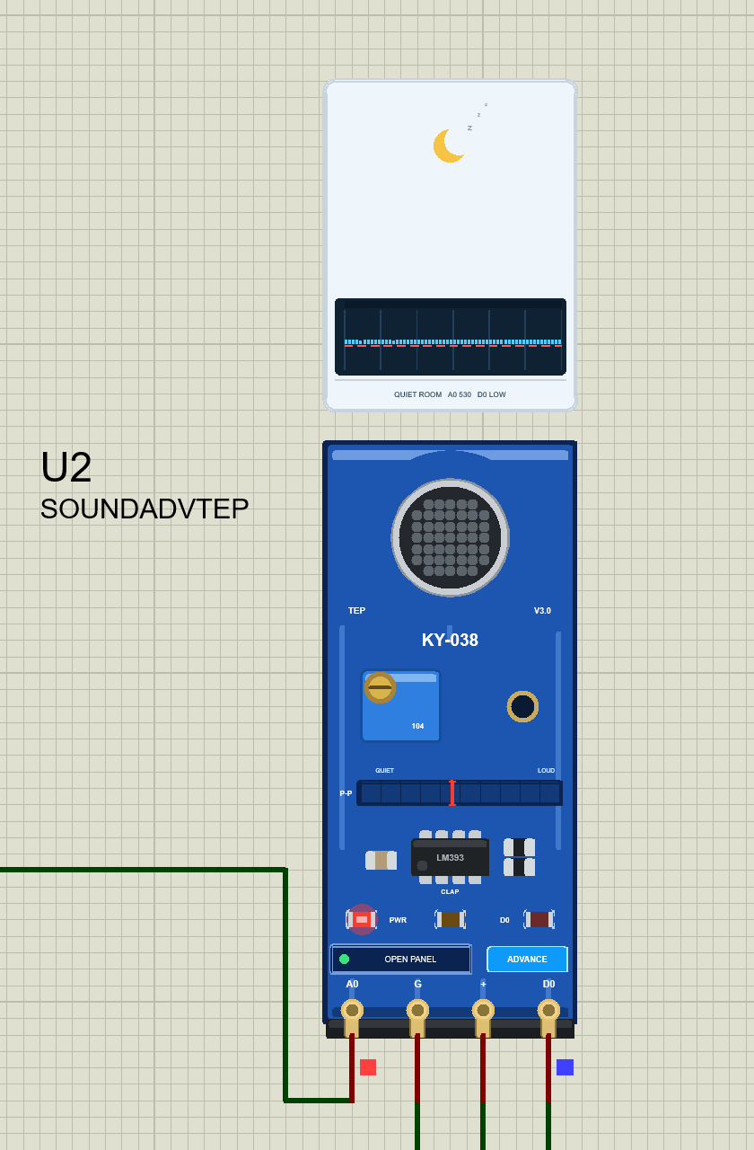
At Run, the "TEP Sound Sensor Advance" pop-up opens with the look of our TEP Serial Monitor and no Windows title bar: move it by its header, resize or minimise it, and reopen it with OPEN PANEL. The header shows the state (for example U2 · MUSIC 80 dB), the Sound and Test tabs and the palette (theme), gear (Settings) and ? (Help) icons; chips below it show the peak-to-peak, D0, the pot and the claps heard.
The Sound Page
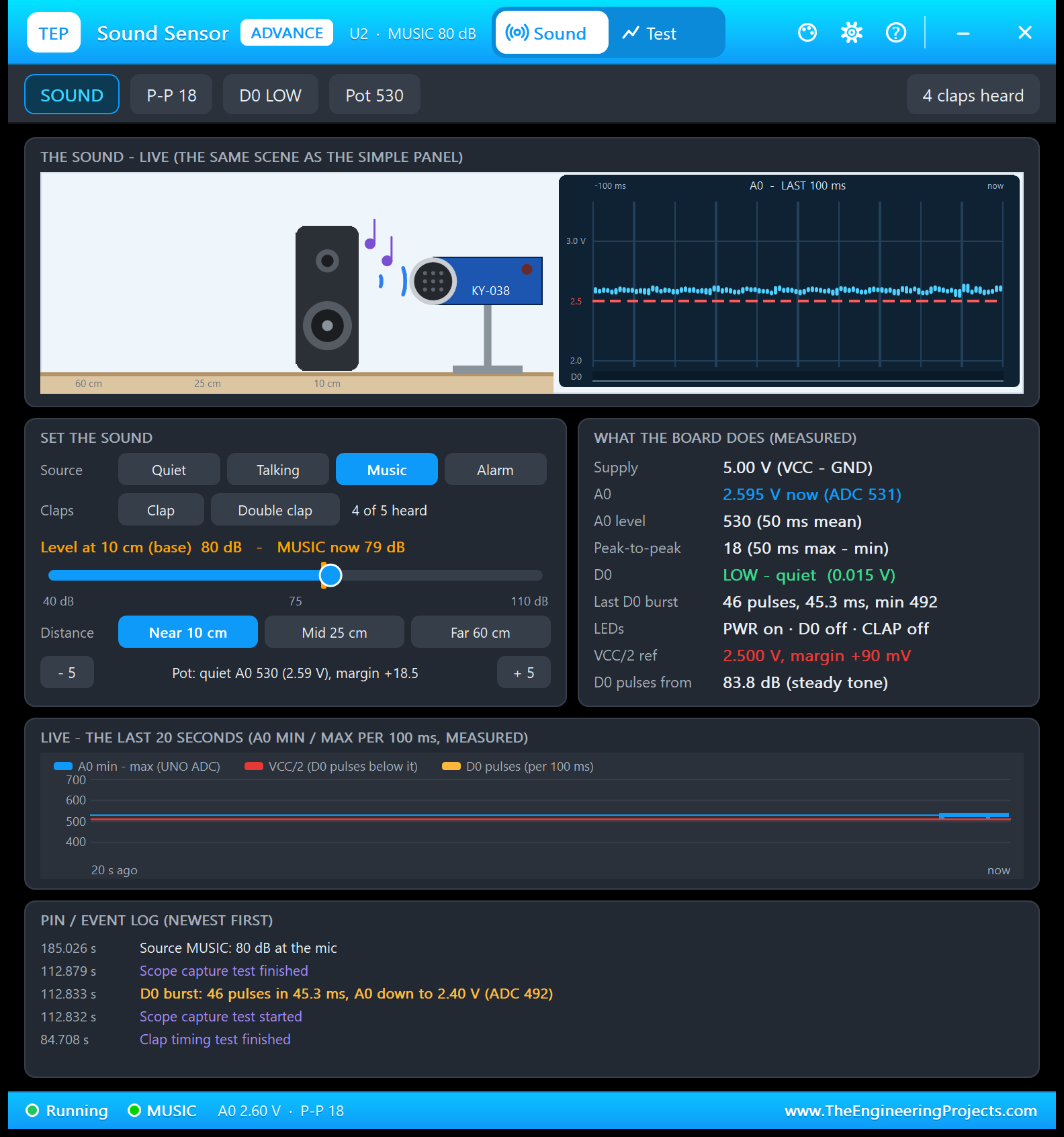
- THE SOUND - LIVE: the same scene as the Simple panel, with the 100 ms scope of A0.
- SET THE SOUND: the four sources, Clap and Double clap with the claps heard (4 of 5 here), a level slider from 40 to 110 dB, the distance and the pot (- 5 / + 5).
- WHAT THE BOARD DOES (MEASURED): the supply, A0 now (2.595 V, ADC 531), the A0 level (530) and peak-to-peak (18) by the demo's 50 ms formula, D0 (LOW, 0.015 V), the last D0 burst, the LEDs, the VCC/2 reference with the margin (+90 mV) and the trip level of this pot, "D0 pulses from 83.8 dB (steady tone)".
- LIVE - THE LAST 20 SECONDS: A0's min and max per 100 ms and the D0 pulses.
- PIN / EVENT LOG (NEWEST FIRST): power, scene changes, D0 bursts, claps and the test tools.
The slider keeps the base level of the source (80 dB) and an amber marker shows the level now: music has a beat, so the line says "MUSIC now 79 dB". The newest D0 burst in the log, "46 pulses in 45.3 ms, A0 down to 2.40 V (ADC 492)", came from the Scope capture tool's 1 kHz tone.
A Double Clap on the Sound Page
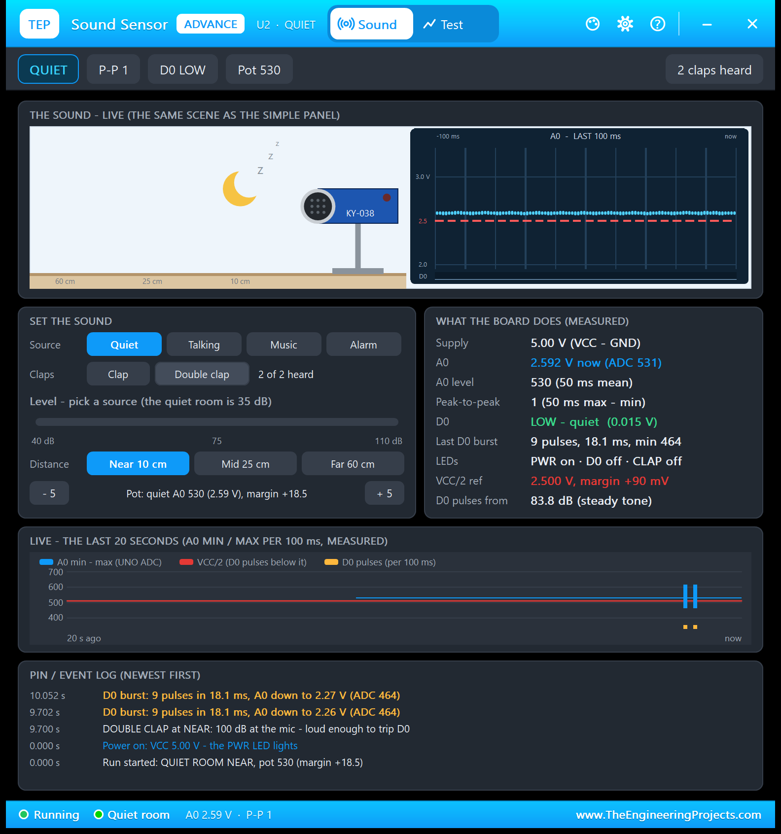
In the quiet room, click Double clap: two claps at 100 dB, far above the 83.8 dB this pot needs, and the page shows 2 of 2 heard. Read the event log from the bottom up:
- 0.000 s: "Run started: QUIET ROOM NEAR, pot 530 (margin +18.5)" and "Power on: VCC 5.00 V - the PWR LED lights".
- 9.700 s: "DOUBLE CLAP at NEAR: 100 dB at the mic - loud enough to trip D0".
- 9.702 s and 10.052 s: "D0 burst: 9 pulses in 18.1 ms", with A0 down to 2.26 V and 2.27 V (ADC 464).
So a clap is not one D0 pulse but 9 pulses in 18.1 ms, and the two bursts are exactly 0.350 s apart; the 20-second chart shows them as two spikes with two D0 marks. On U4, the demo sketch printed the same two claps (see the results below).
The Test Page: Four Measured Sound Test Tools
The four tools on the Test tab take the scene over while they run and put it back when they end. They never talk to your Arduino: they play a sound and measure the A0 and D0 node voltages at every simulation timepoint, so every number is what the circuit really did. Each tool ends with a bold "Good for:" line. All results come from U2 with the demo sketch running.
1. Level Sweep: How Big Is the Swing, and When Does D0 Trip?
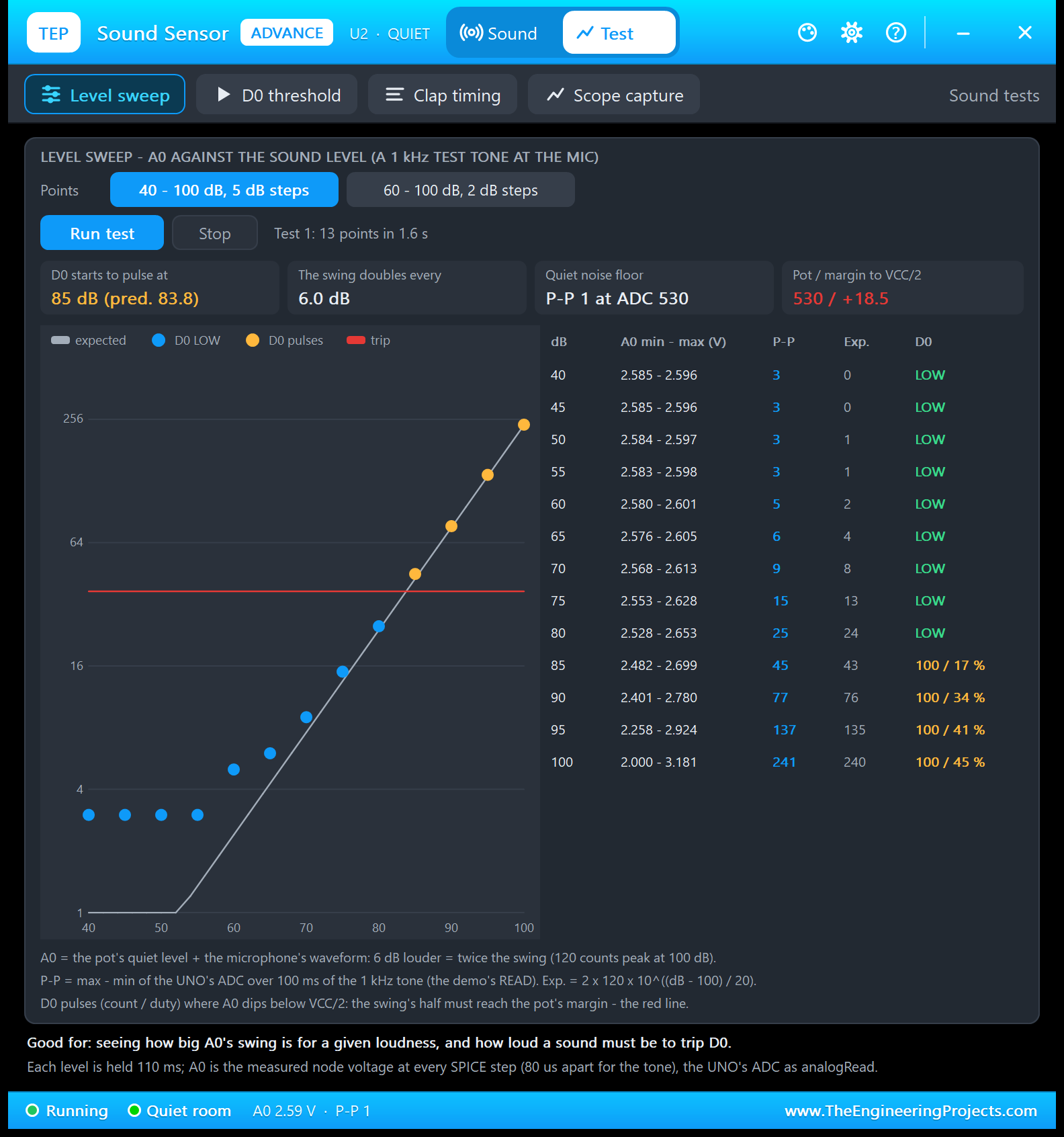
Good for: "seeing how big A0's swing is for a given loudness, and how loud a sound must be to trip D0." Choose 13 points (40 to 100 dB in 5 dB steps) or 21 points (60 to 100 dB in 2 dB steps). The tool plays a 1 kHz test tone and holds each level for 110 ms:
| dB | A0 min - max (V) | P-P | Exp. | D0 (pulses / duty) |
|---|---|---|---|---|
| 40 | 2.585 - 2.596 | 3 | 0 | LOW |
| 45 | 2.585 - 2.596 | 3 | 0 | LOW |
| 50 | 2.584 - 2.597 | 3 | 1 | LOW |
| 55 | 2.583 - 2.598 | 3 | 1 | LOW |
| 60 | 2.580 - 2.601 | 5 | 2 | LOW |
| 65 | 2.576 - 2.605 | 6 | 4 | LOW |
| 70 | 2.568 - 2.613 | 9 | 8 | LOW |
| 75 | 2.553 - 2.628 | 15 | 13 | LOW |
| 80 | 2.528 - 2.653 | 25 | 24 | LOW |
| 85 | 2.482 - 2.699 | 45 | 43 | 100 / 17 % |
| 90 | 2.401 - 2.780 | 77 | 76 | 100 / 34 % |
| 95 | 2.258 - 2.924 | 137 | 135 | 100 / 41 % |
| 100 | 2.000 - 3.181 | 241 | 240 | 100 / 45 % |
From 70 dB up, the measured swing (P-P) follows the expected one (Exp.) within two counts and grows 1.78 times every 5 dB: 6.0 dB per doubling. The softest tones are lost in the noise (P-P 3); the silent noise floor is P-P 1. D0 stays LOW up to 80 dB (a peak of about 12 counts, less than the 18.5-count margin) and starts at 85 dB, with 100 pulses in 100 ms: once per cycle of the tone. The prediction, 83.8 dB, lies between the two test points. The duty grows from 17 to 45 % as the dips get deeper. On the log chart, orange dots mean D0 pulses, and the red line is the trip level.
2. D0 Threshold: Setting the Pot
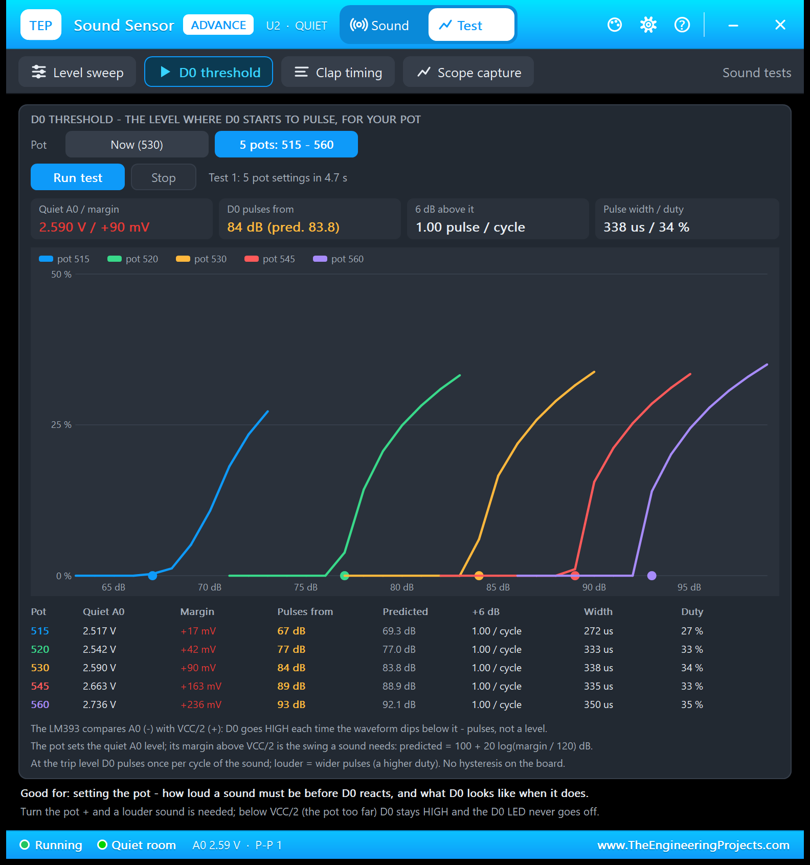
Good for: "setting the pot - how loud a sound must be before D0 reacts, and what D0 looks like when it does." Choose the pot as it is now (530) or five pots from 515 to 560. For each pot, the tone rises 1 dB every 60 ms from 6 dB below the predicted trip level until D0 pulses; then the tool plays it 6 dB louder:
| Pot | Quiet A0 | Margin | Pulses from | Predicted | +6 dB | Width | Duty |
|---|---|---|---|---|---|---|---|
| 515 | 2.517 V | +17 mV | 67 dB | 69.3 dB | 1.00 / cycle | 272 us | 27 % |
| 520 | 2.542 V | +42 mV | 77 dB | 77.0 dB | 1.00 / cycle | 333 us | 33 % |
| 530 | 2.590 V | +90 mV | 84 dB | 83.8 dB | 1.00 / cycle | 338 us | 34 % |
| 545 | 2.663 V | +163 mV | 89 dB | 88.9 dB | 1.00 / cycle | 335 us | 33 % |
| 560 | 2.736 V | +236 mV | 93 dB | 92.1 dB | 1.00 / cycle | 350 us | 35 % |
Every pot trips within 2.3 dB of the prediction, 100 + 20 log(margin / 120) dB. Pot 515 is only 17 mV above VCC/2 and trips at 67 dB; pot 560 sits 236 mV above it and needs 93 dB. Six dB above the trip level, D0 pulses exactly once per cycle, 272 to 350 us wide, and the chart shows the duty climbing with the level. This is the classic advice "turn the pot until the D0 LED just goes off in a quiet room" in numbers.
3. Clap Timing: Debounce and Double Claps
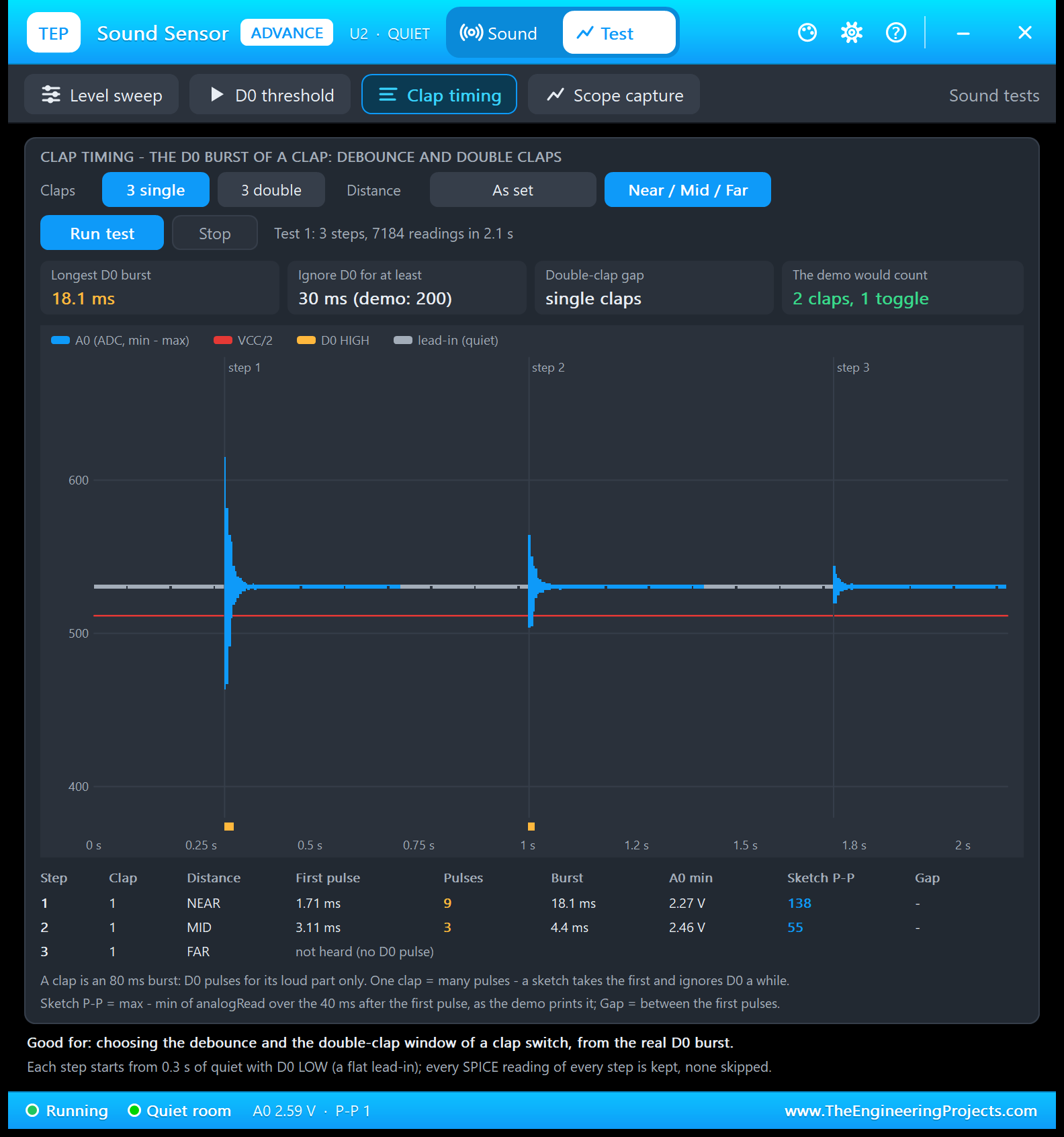
Good for: "choosing the debounce and the double-clap window of a clap switch, from the real D0 burst." Choose 3 single or 3 double claps, at Near / Mid / Far or as set. Each step starts from 0.3 s of quiet, and every SPICE reading is kept: here 7184 readings in 2.1 s.
| Step | Distance | First pulse | Pulses | Burst | A0 min | Sketch P-P |
|---|---|---|---|---|---|---|
| 1 | NEAR | 1.71 ms | 9 | 18.1 ms | 2.27 V | 138 |
| 2 | MID | 3.11 ms | 3 | 4.4 ms | 2.46 V | 55 |
| 3 | FAR | Not heard (no D0 pulse) | - | - | - | - |
A clap is an 80 ms burst, but D0 pulses only during its loud start: 9 pulses in 18.1 ms at NEAR, 3 in 4.4 ms at MID, and none at FAR, where A0 never reaches VCC/2. "Sketch P-P" is what the demo prints: the max - min of analogRead over the 40 ms after the first pulse.
The cards turn this into settings: with a longest burst of 18.1 ms, ignore D0 for at least 30 ms after a clap (the demo uses 200 ms). And "The demo would count 2 claps, 1 toggle": the NEAR and MID claps came about 0.7 s apart, inside the demo's 0.8 s window, so its rule takes them as a double clap.
4. Scope Capture: The Real Waveform
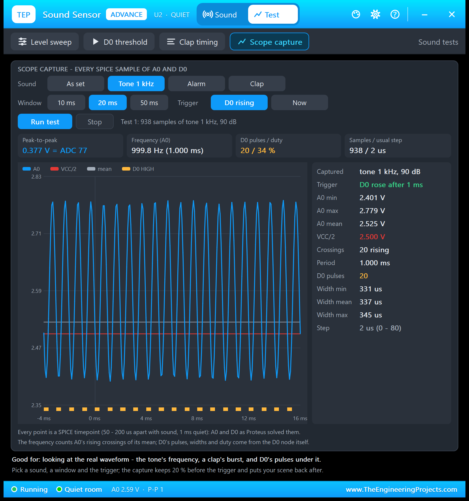
Good for: "looking at the real waveform - the tone's frequency, a clap's burst, and D0's pulses under it." Pick the sound (as set, the 1 kHz tone, the alarm or a clap), a 10, 20 or 50 ms window and the trigger (D0 rising or now); 20 % of the capture lies before the trigger.
Here, the 1 kHz tone at 90 dB: A0 swings from 2.401 to 2.779 V, a peak-to-peak of 0.377 V = ADC 77, the same 77 counts as the level sweep at 90 dB. From A0's 20 rising crossings of its mean, the tool finds 999.8 Hz. Under every dip below the red VCC/2 line sits one D0 pulse: 20 pulses, 331 to 345 us wide, a duty of 34 %. The 938 samples are Proteus's own timepoints, 2 us apart here, much finer than the 80 us our model asks for.
Settings and Help
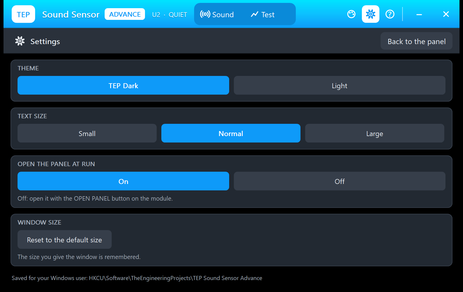
The gear opens Settings: the theme (TEP Dark or Light), the text size, open the panel at Run, and Reset to the default size, saved for your Windows user.
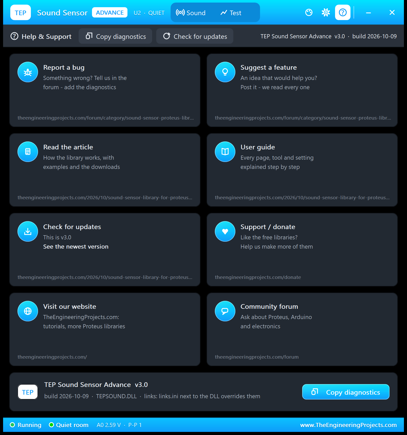
The ? icon opens Help & Support: eight cards with their links (bug reports and ideas on the sound sensor board of our forum, this article, updates, donate, our website and the forum) and Copy diagnostics for a bug report. A links.ini next to the DLL can change the links.
KY-038 Clap Switch with Arduino in Proteus
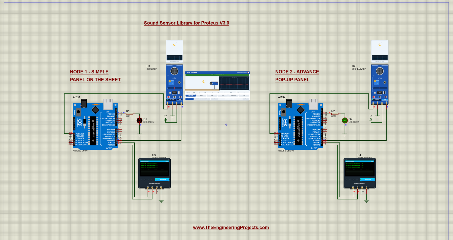
Open Sound-Sensor-ArduinoUnoV3.pdsprj from the Proteus Simulation folder, with Clap_Switch.hex and both DLLs beside it. Its two Arduino UNOs from our Arduino Library for Proteus V3.0 run the same HEX file:
- NODE 1 - SIMPLE: UNO 1 (ARD1) with the Sound Simple (U1), the green lamp LED D1 on D13 and Serial Monitor U3.
- NODE 2 - ADVANCE: UNO 2 (ARD2) with the Sound Advance (U2), the green lamp LED D2 on D13 and Serial Monitor U4.
Wiring
| From | To | Why |
|---|---|---|
| Sensor + / G | +5V terminal / ground | Power (the PWR LED lights) |
| Sensor A0 | Arduino A0 | The microphone signal for analogRead() |
| Sensor D0 | Arduino D2 | The comparator output for digitalRead() |
| Green LED + 220 Ω | D13 to GND | The lamp that the claps switch (the UNO's own D13 LED follows it) |
| Serial Monitor RXD / TXD / GND | Arduino D1 / D0 / ground | Shows what the Arduino prints, sends what you type |
| Serial Monitor RXD2 | Not connected | The sensor has no serial line to watch |
A0 is the first of the UNO's six analog inputs (see our Introduction to Arduino UNO). The sketch polls D0 with digitalRead(); for an interrupt, use attachInterrupt() on D2 (INT0), because Proteus 8.5's ATmega328P does not run pin-change interrupts.
The Arduino Code
The sketch, Clap_Switch.ino, needs no extra library. First the pins and the four settings the commands can change:
const int SOUND_A0 = A0;      // analog output of the sensor (the microphone signal)
const int SOUND_D0 = 2;       // digital output of the sensor (HIGH pulses = loud sound)
const int LAMP_LED = 13;      // the lamp (the UNO's on-board LED)

unsigned long IGNORE_MS = 200;        // after a clap, ignore D0 for this long (one clap = many pulses)
unsigned long DOUBLE_CLAP_MS = 800;   // the second clap must come within this time
unsigned long REPORT_MS = 2000;       // print the sound level every 2 s (EVERY ms; 0 = off)
int clapsToSwitch = 2;                // CLAPS 1 or 2
The heart of the sketch reads A0 for a number of milliseconds and returns the peak-to-peak swing; the mean comes back in average:
int peakToPeak(unsigned long ms, long &average) {
  int lowest = 1023, highest = 0;
  long sum = 0;
  int count = 0;
  unsigned long start = millis();
  while (millis() - start < ms) {
    int value = analogRead(SOUND_A0);
    if (value < lowest) lowest = value;
    if (value > highest) highest = value;
    sum += value;
    count++;
  }
  average = count > 0 ? sum / count : 0;
  return highest - lowest;
}
setup() prints three start lines:
void setup() {
  Serial.begin(9600);
  pinMode(SOUND_D0, INPUT);
  pinMode(LAMP_LED, OUTPUT);
  digitalWrite(LAMP_LED, LOW);
  Serial.println("Clap Switch - KY-038 Sound Sensor - The Engineering Projects");
  Serial.println("Clap twice to switch the lamp (D13) ON / OFF");
  Serial.println("Type HELP for the commands.");
}
In loop(), a clap is the first HIGH on D0 after the ignore time. The sketch measures it over the next 40 ms and checks whether it is the second clap of a pair:
  // 1. A clap: the first HIGH pulse on D0 after the ignore time
  if (digitalRead(SOUND_D0) == HIGH && now - lastClapTime > IGNORE_MS) {
    long average;
    int level = peakToPeak(40, average);     // how loud was it?
    bool second = (claps == 1 && now - lastClapTime <= DOUBLE_CLAP_MS);
    lastClapTime = now;
    clapCount++;

    Serial.print("Clap!  A0 peak-to-peak: ");
    Serial.print(level);
A second clap within the window toggles the lamp, and the sketch prints "(2 of 2)" with the new lamp state:
    } else if (second) {
      claps = 0;
      setLamp(!lampOn);                       // two claps: toggle the lamp
Otherwise, it is the first clap of a pair:
    } else {
      claps = 1;
      Serial.print("   (1 of 2) - clap again within ");
      printSeconds(DOUBLE_CLAP_MS);
      Serial.println(" s");
    }
If the window runs out, the pair starts again:
  // 2. Only one clap and the time is up: start again
  if (claps == 1 && millis() - lastClapTime > DOUBLE_CLAP_MS) {
    claps = 0;
    Serial.println("Only one clap - lamp unchanged");
  }
The claps and the LAMP command switch the lamp through one function:
void setLamp(bool on) {
  lampOn = on;
  digitalWrite(LAMP_LED, lampOn ? HIGH : LOW);
}
Every 2 s, and only then, the sketch prints the level line by itself:
  // 3. Every 2 s (EVERY ms): the quiet level and the sound level - the only line printed by itself
  if (REPORT_MS > 0 && millis() - lastReport >= REPORT_MS) {
    lastReport = millis();
    printLevel();
  }
It shows the mean A0 level and the peak-to-peak over 50 ms, D0 and the lamp:
void printLevel() {
  long average;
  int level = peakToPeak(50, average);
  Serial.print("A0 level: ");
  Serial.print(average);
  Serial.print("   sound peak-to-peak: ");
  Serial.print(level);
  Serial.print("   D0: ");
  Serial.print(digitalRead(SOUND_D0) == HIGH ? "HIGH" : "LOW");
  Serial.print("   lamp: ");
  Serial.println(lampOn ? "ON" : "OFF");
}
The commands are read one line at a time, in upper case. IGNORE accepts 10 to 2000 ms:
  } else if (strncmp(cmd, "IGNORE", 6) == 0 && numberAfter(cmd + 6) >= 10 && numberAfter(cmd + 6) <= 2000) {
    IGNORE_MS = numberAfter(cmd + 6);
    Serial.print("After a clap D0 is ignored for ");
    Serial.print(IGNORE_MS);
    Serial.println(" ms");
CLAPS 1 makes it a single-clap switch:
  } else if (strcmp(cmd, "CLAPS 1") == 0 || strcmp(cmd, "CLAPS 2") == 0) {
    clapsToSwitch = cmd[6] - '0';
    claps = 0;
    Serial.println(clapsToSwitch == 1 ? "One clap switches the lamp" : "Two claps switch the lamp");
HELP prints two short lines, so they fit the Serial Monitor's Simple interface:
void printHelp() {
  Serial.println("Commands: HELP, STATUS, READ, EVERY ms (0 = off),");
  Serial.println("  IGNORE ms, GAP ms, CLAPS 1 or 2, LAMP ON, LAMP OFF");
}
The settings live in RAM, so a new Run brings back the defaults. To change the sketch, export a new HEX file and load it into both UNOs; see How to get the HEX file from Arduino. New to Arduino? Start with our Arduino Tutorial for Beginners.
Serial Monitor Commands
| Command | What it does |
|---|---|
| HELP | The command list (two lines) |
| STATUS | The lamp, the claps so far and the settings below (two lines) |
| READ | One level line now |
| EVERY ms | The level line every ms milliseconds; EVERY 0 = no level lines, READ still works (default 2000) |
| IGNORE ms | After a clap, ignore D0 for this long, 10 to 2000 ms (default 200) |
| GAP ms | The second clap must come within this time, 100 to 5000 ms (default 800) |
| CLAPS 1 / 2 | One clap or two claps switch the lamp (default 2) |
| LAMP ON / OFF | Switch the lamp by hand |
How to Run the Demo
- Press Run. Both Serial Monitors (9600 baud) and U2's pop-up open, and the PWR LEDs light.
- On U1's panel, click CLAP: the hands clap, the rings turn red, the D0 and CLAP LEDs flash, and U3 prints "(1 of 2)", then "Only one clap - lamp unchanged". Click DOUBLE CLAP: lamp D1 lights.
- Try MID 25 cm (claps are still heard) and FAR 60 cm (nothing is printed until you click POT - three times). Then try MUSIC, TALKING and ALARM.
- Use the quick buttons: STATUS, READ and EVERY 0 on U3; CLAPS 1 on U4.
- On U2, try the Sound page and the four tools; close its window and reopen it with OPEN PANEL.
Sound Sensor Proteus Simulation Results
The Serial Monitor in Its Simple Interface
Both monitors in this demo run in the Simple interface of our TEP Serial Monitor, as in every monitor screenshot here. Only the log, the send box and one slim toolbar row stay visible (baud rate, follow, pause, search and clear), so the window stays small.
- Switch to it: right-click the log and choose Simple interface, or press Ctrl+Shift+U.
- Back to the full view: click the corner button (the expand arrows at the top right), press Esc or Ctrl+Shift+U, or right-click and choose Full interface.
- Your choice is remembered.
Type commands such as STATUS in the send box and press Enter; the quick buttons come back with the full view. No line the sketch prints is longer than 80 characters, so every line fits. Read all about the monitor in TEP Serial Monitor Advance for Proteus.
Start-Up
After Run, U3 prints the three start lines and then, every 2 s, the level line:
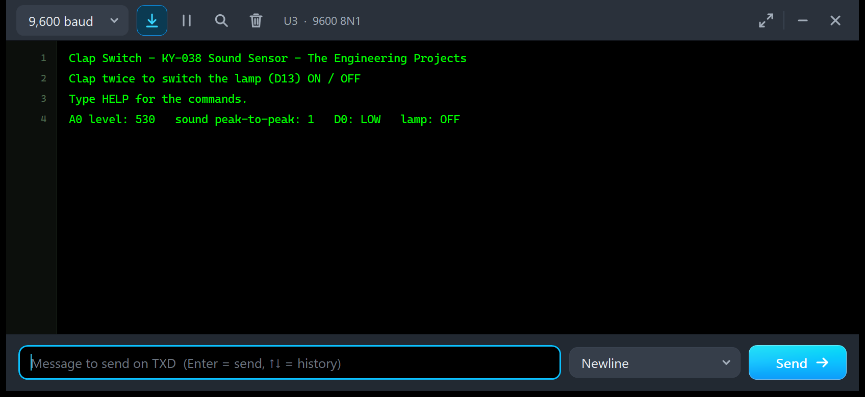
Clap Switch - KY-038 Sound Sensor - The Engineering Projects
Clap twice to switch the lamp (D13) ON / OFF
Type HELP for the commands.
A0 level: 530   sound peak-to-peak: 1   D0: LOW   lamp: OFF
In the quiet room, the mean A0 level is 530, the pot's quiet level, and the peak-to-peak is 1: the model's 1-count noise floor. A real board shows a few counts of noise too.
A Double Clap Switches the Lamp
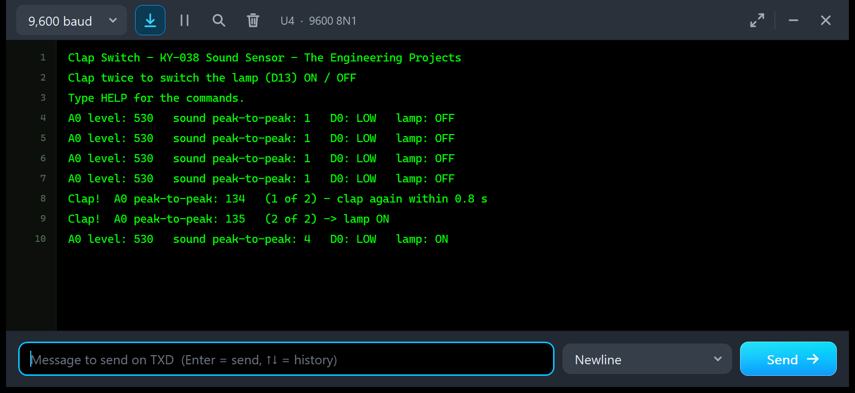
Every 2 s a level line, then the double clap from U2's Sound page:
A0 level: 530   sound peak-to-peak: 1   D0: LOW   lamp: OFF
A0 level: 530   sound peak-to-peak: 1   D0: LOW   lamp: OFF
A0 level: 530   sound peak-to-peak: 1   D0: LOW   lamp: OFF
A0 level: 530   sound peak-to-peak: 1   D0: LOW   lamp: OFF
Clap!  A0 peak-to-peak: 134   (1 of 2) - clap again within 0.8 s
The next line is the second clap, 0.35 s later: "Clap! A0 peak-to-peak: 135 (2 of 2)", followed by the sketch's arrow and lamp ON. Lamp D2 lights, and the next level line ends with "lamp: ON". These are the two bursts of 9 pulses from the Sound page's event log above.
The Alarm Switches the Lamp Too
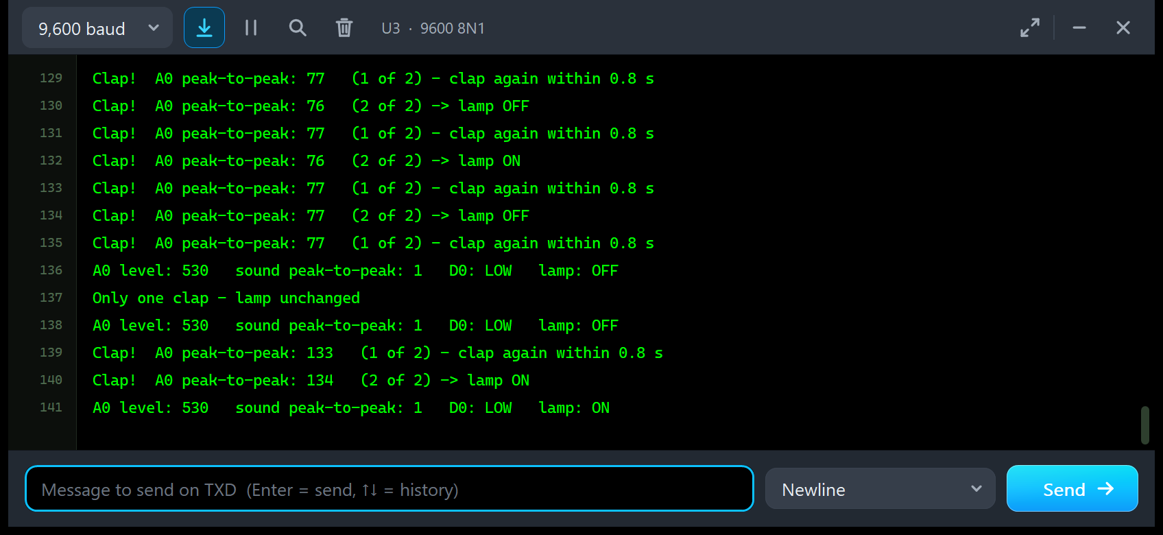
This screenshot shows a real-world gotcha. With ALARM at NEAR on U1, each beep prints "Clap!" with a peak-to-peak of 76 or 77, the alarm's swing at 90 dB, and every second beep toggles the lamp:
| Lines | Peak-to-peak | What the sketch did |
|---|---|---|
| 129, 130 | 77, 76 | A pair: lamp OFF |
| 131, 132 | 77, 76 | A pair: lamp ON |
| 133, 134 | 77, 77 | A pair: lamp OFF |
| 135 | 77 | The first of a pair; no second beep followed |
| 139, 140 | 133, 134 | A double clap: lamp ON |
Lines 135 to 139 in full:
Clap!  A0 peak-to-peak: 77   (1 of 2) - clap again within 0.8 s
A0 level: 530   sound peak-to-peak: 1   D0: LOW   lamp: OFF
Only one clap - lamp unchanged
A0 level: 530   sound peak-to-peak: 1   D0: LOW   lamp: OFF
Clap!  A0 peak-to-peak: 133   (1 of 2) - clap again within 0.8 s
After line 135 the alarm stopped, so the 0.8 s window ran out: "Only one clap - lamp unchanged". Then a DOUBLE CLAP printed 133 and 134 and switched the lamp ON. A real clap switch does the same next to an alarm clock: move the clock further away or turn the pot up.
Troubleshooting
- A clap prints nothing: it is too quiet for the pot (FAR at the default pot). Click POT - or move to NEAR; the banner and the event log say "too quiet for the pot".
- The D0 LED is always on, "POT TOO FAR - D0 STUCK HIGH": click POT + until the D0 LED goes off.
- One clap counts twice: raise IGNORE (the Clap timing tool shows the burst length).
- The alarm switches the lamp: each beep trips D0, as on a real clap switch; move it to MID or click POT +.
- The simulation runs slower while a sound plays (about 0.4 x real time with the pop-up open): a sound needs time steps of 50 to 200 us, a quiet room only 1 ms.
- The Test tab says "Cannot start: ...": the reason is in the message (no power, or another test runs).
- The part is not simulated, no panel or no monitor window: TEPSOUND.DLL or TEPSERIALMON.DLL is missing from MODELS and the project folder; click OPEN MONITOR on a closed monitor.
- The Advance pop-up does not appear: click OPEN PANEL, or turn "Open the panel at Run" back on.
- A pin-change interrupt on D0 never fires: Proteus 8.5's ATmega328P does not run them; use digitalRead() or attachInterrupt() on D2 (INT0).
Things to Know Before Using a Real KY-038 Module
The demo sketch uses only the Arduino core, so it runs on a real UNO and KY-038, too. Keep in mind:
- Supply: 3.3 to 5 V. A0 and the comparator's VCC/2 reference both follow VCC.
- A0 is the raw microphone signal: a quiet room reads about 500 to 530, a clap close by swings it by tens to more than 100 counts, speech by a few. Read it as a peak-to-peak over about 50 ms.
- D0 pulses at the sound's frequency (no hysteresis): take the first pulse and ignore D0 for 100 to 200 ms, otherwise one clap counts many times.
- The D0 LED always on means the pot is turned too far: turn it back until the LED just goes off in a quiet room.
- Check your D0 polarity: a few boards and tutorials have D0 the other way round, and the 3-pin "sound detection module" (OUT, GND, VCC) is active LOW. Watch your D0 LED.
- KY-037: the same board with a bigger microphone.
- Levels: the dB values in our scene are typical sound levels. The real board has no dB scale, so find your thresholds with your own sounds.
- Current: the real board draws a few mA.
Limitations of the Simulation
- Modelled: A0 as the microphone node (4.7 k output resistance, following VCC), D0 as the LM393's open collector with a 10 k pull-up (no hysteresis), the PWR LED's load, the supply, the sounds as sums of tones, the distance, the pot and a 1-count noise floor.
- Not modelled: the microphone's frequency response and direction, echoes, two sounds mixed with real phase, the LM393's own microsecond delays, the KY-037 and the 3-pin modules.
- The model is our own implementation, written from the module's published descriptions. The HEX file contains the Arduino AVR core 1.8.6, which includes LGPL-licensed code; its source code is on GitHub.
- Tested in Proteus 8.5 in October 2026 (the demo, both panels, the four tools and every screenshot here) and with 1,375 automatic PC checks, all passed, 32 of them with the real demo sketch on two UNOs. Proteus 7 is not supported.
Want more boards with an LM393 comparator? See our Flame Sensor Library for Proteus V2.0 and our LDR Sensor Library for Proteus. To switch a lamp on motion instead, take our PIR Sensor Library for Proteus V4.0.
So, that was all about the Sound Sensor Library for Proteus V3.0. I hope the live sound scene, the measured A0 wave, the pulsing D0 and the four test tools make the KY-038 much easier to understand, so your clap switch works the first time you wire a real module. If you use the Sound Sensor Library for Proteus in a project, please share your feedback in the comments or in our forum, and if you have any questions, ask in the comments and I will help you out. Till the next tutorial, take care and have fun!
Comments
0