


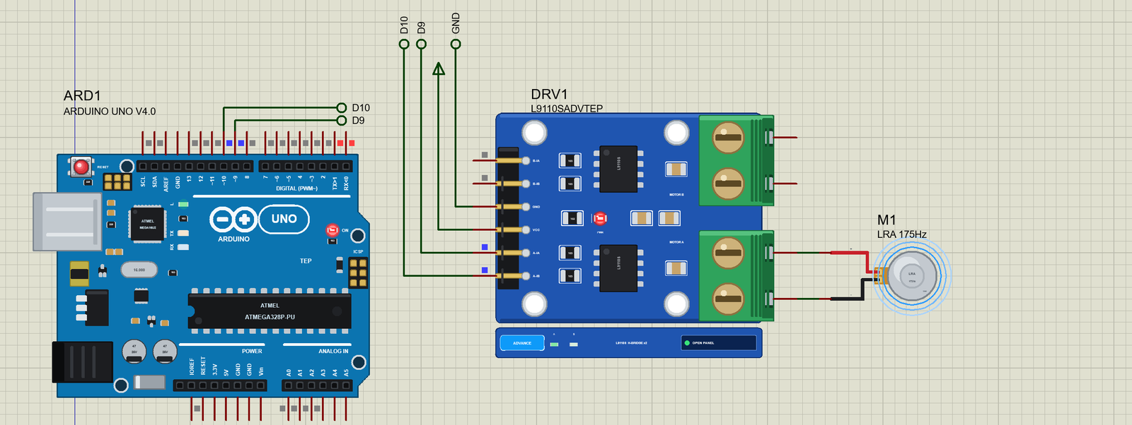
LRA Vibration Motor Library for Proteus Simulation


Hello friends, I hope you all are doing great. Today, I am going to share the new LRA Vibration Motor Library for Proteus Simulation, the 36th library of our motor series. If you have searched for a Proteus simulation of an LRA, this is the small coin that makes the crisp taps in phones, smart watches and game controllers: a linear resonant actuator. Unlike the older coin vibration motor with its spinning weight, an LRA moves a small mass back and forth on springs, and it only works well at one frequency. That makes it fast and crisp, and it also makes it the part students most often drive the wrong way.
LRA Vibration Motor Library for Proteus Simulation
Latest version: V1.0 (November 2026, this tutorial)
Helping Tools
- Serial Monitor Advance: a serial terminal window for the UART of your board
- Serial Monitor Expert: the serial monitor with extra debugging tools
- LCD Library for Proteus V3.0: 16x2, 20x4 and I2C LCDs to show your readings
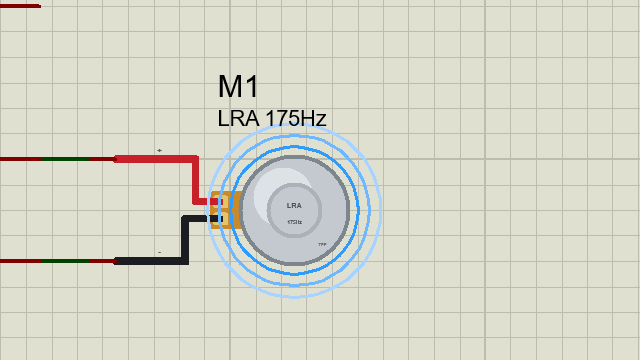
Our library brings a 10 mm coin LRA into your Proteus simulation at its true size, with its steel can, its flex tab and its red and black leads. The simulation model follows the maker's datasheet of the common 10 mm coin LRA: the coil, its back-EMF, and the mass on its springs with a resonance at 175 Hz and a quality factor of 33. It is solved together with the circuit, so whatever drives it, the LRA answers like the real one. The pop-up draws the mass with its swing, plots the frequency response with the working point and shows a scope of the drive and the back-EMF. It also measures every burst: how fast the vibration rises, how long it rings on, and how much an active brake helps. In the demo, an Arduino makes a 175 Hz wave through our L9110S driver and sweeps the frequency through the resonance.
NOTICE: Our team has put a lot of effort into these small parts: the bodies, the animation and the pop-ups are all our own design, and you get them free. Your feedback is the fuel that keeps us going, so please tell us what you think in the comments below or in the Motor Driver board of our forum. And if our free libraries help you, you can buy us a coffee. So, let's get started with the LRA Vibration Motor Library for Proteus Simulation:
What is an LRA?
An LRA (linear resonant actuator) is a tiny loudspeaker without the cone. A voice coil sits in a magnetic field, and a small mass rides on springs. AC current in the coil pushes the mass one way and then the other, and the springs bring it back. Mass and springs together have a natural frequency, the resonance: drive the coil at that frequency and every push adds to the swing, so a small current makes a strong vibration. Drive it a few hertz away and the pushes fight the springs, and the vibration falls away.
This is the big difference from an ERM, the eccentric rotating mass motor in a classic coin vibration motor. An ERM is a DC motor: give it DC and it spins and shakes, at any voltage. An LRA needs AC at its own resonance; a DC voltage only pushes the mass to one side and holds it there. In return, an LRA starts and stops in a few tens of milliseconds, uses less power and gives sharp, clean taps. Haptic driver chips drive it with a sine-like wave and find its resonance by listening to its back-EMF.
| The 10 mm coin LRA (maker's datasheet) | |
|---|---|
| Rated drive | 2 Vrms sine at 175 Hz (2.05 Vrms max) |
| Current | 67 mA typical, 90 mA max at the rated drive |
| Vibration | 1.5 G peak-to-peak typical (1 G min) on a 100 g test sled |
| Coil | 24.4 ohm, 85.8 µH |
| Resonance | 174 Hz ± 8 Hz |
| Timing | rise 37 ms, stop 177 ms (typical) |
| Size | 10 mm across, 3.7 mm thick, 2 g |
The datasheet's frequency-response curve shows how narrow the resonance is: the peak is only about 6.5 Hz wide at half power. Our model reproduces the curve, the current and the timing from that data.
Features of the LRA Vibration Motor Library for Proteus Simulation
- The real LRA at true scale: the 10 mm steel can with its rim and embossed ring, the flex tab and the leads; rings round the can at run time show the vibration.
- The physics, not a lookup: the coil's resistance and back-EMF and the mass on its springs, solved with the circuit by the trapezoidal rule so the resonance rings as it should.
- Fitted to the datasheet: at 2 Vrms and 175 Hz it draws 67 mA at the drive frequency and shakes a 100 g sled at 1.5 G; it rises in about 35 ms and rings on for about 180 ms.
- Measured every cycle: the drive's fundamental and frequency, the phase of the back-EMF against the drive, the currents, the power, and each burst's rise and stop, with and without an active brake.
- Two properties: the resonance (F0, for the ± 8 Hz spread of real parts) and the mass it shakes (MOUNT).
- A pop-up: the mass on its springs with its swing, the frequency response at the present drive with the working point, a scope of the last 20 ms, eight live values, graphs, an event log and a check page.
- A complete package: about 1.2 MB with the library, our Arduino UNO V4.0 and the demo, without the source code of the model.
The LRA in Proteus
The device is LRACOIN10TEP in TEPLRA10.LIB, under Electromechanical > Motors, with the prefix M and the analog model TEPLRA10.DLL. Search LRACOIN in Pick Devices. Its pins sit at the ends of its leads: + on the red lead and - on the black, 400 thou apart, the same spacing as the outputs of our L9110S driver. An LRA has no real polarity; the colours only tell you which way the mass moves first.
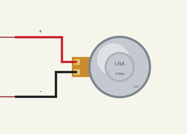
Two properties describe it. F0 is the resonant frequency in hertz (175); real parts spread over 174 ± 8 Hz, so you can try a part that is off its rating. MOUNT is the mass the LRA is fixed to, in grams (100, the datasheet's test sled). The vibration you feel is the reaction of the moving mass through its mounting, so a light wristband shakes harder than a heavy phone.
Download LRA Vibration Motor Library for Proteus Simulation
Click the button below to download LRA-Vibration-Motor-Library-for-Proteus-v1.0.zip (about 1.2 MB, without the source code of the models):
LRA Vibration Motor Library for Proteus V1.0- README.txt: installation, the demo, the wiring, troubleshooting and the limits of the simulation.
- Proteus Library Files:
TEPLRA10.LIBandArduinoV4TEP.LIB. - Proteus Model Files:
TEPLRA10.DLLandTEPARDUINO.DLL. - Arduino Code: the demo sketch.
- Proteus Simulation: the demo project, its HEX file and copies of the DLLs.
No Proteus yet? Read How to Download and Install Proteus 7 and 8. New to libraries? Follow How to Install a New Library in Proteus.
How to Install LRA Vibration Motor Library for Proteus Simulation
- Close Proteus and extract the whole zip file, for example to your Desktop.
- Copy the files from Proteus Library Files into the LIBRARY folder of Proteus.
- Copy the files from Proteus Model Files into the MODELS folder.
- Delete
TEPLRA10.IDXfrom the LIBRARY folder if it is there. - The demo's driver is our separate L9110S Motor Driver Library for Proteus: install its LIB and DLL too.
- Start Proteus, press P and search for LRACOIN.
Proteus Simulation of an LRA with Arduino
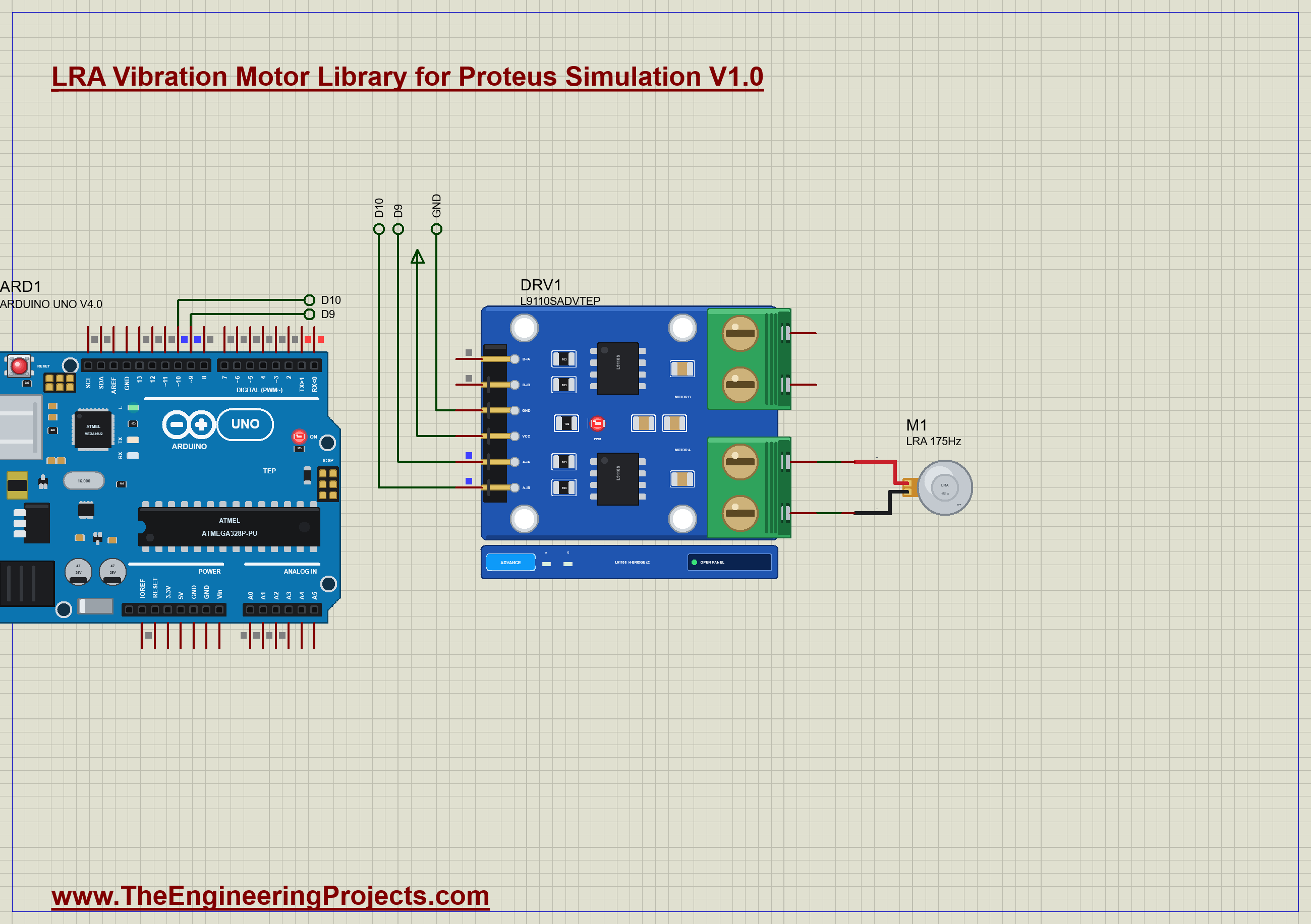
The demo has our Arduino UNO Library for Proteus V4.0 with its built-in monitor, the same window as our TEP Serial Monitor Advance for Proteus, and our L9110S driver on the 5 V rail. The UNO drives A-IA from D9 and A-IB from D10, and the driver's A-OA and A-OB go straight to the LRA M1, which sits on the datasheet's 100 g sled. The driver comes from our separate L9110S library (TEPL9110S.LIB and TEPL9110S.DLL), so install it first. Open LRA-L9110S-ArduinoUnoV4.pdsprj.
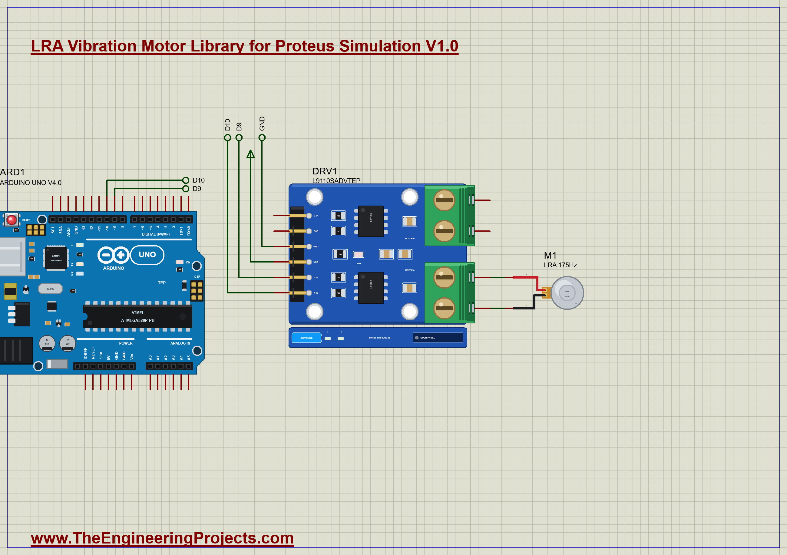
The Sketch
An LRA needs AC, and an H-bridge only knows plus, zero and minus. So the sketch builds a three-level wave in a Timer1 interrupt: a pulse of +5 V, a pause with both outputs low, a pulse of -5 V, a pause. The period sets the frequency and the pulse's width sets the amplitude. Each interrupt sets the outputs and schedules the next edge:
  uint16_t next;
  if (phase == 0) { drive(polarity); next = onTicks; }
  else if (phase == 2) { drive(-polarity); next = onTicks; }
  else { drive(0); next = halfTicks - onTicks; }
The pulse width comes from the wanted RMS voltage at the fundamental. For a three-level wave the fundamental is 4 / π × the height × sin(π × D / 2), with D the pulse's share of each half period, so the sketch solves that for D:
  uint16_t half = (uint16_t)(1000000.0 / f);
  float s = v * sqrt(2.0) * M_PI / (4.0 * SUPPLY);
To brake, the wave simply flips its polarity at the start of a cycle, so it pushes against the motion for a few cycles before it stops:
if (phase == 0 && brakeReq) { brakeReq = false; polarity = -polarity; }After the program you can type commands in the monitor: f 180 plays 180 Hz, v 1.5 sets 1.5 Vrms, s stops and b brakes.
LRA Simulation Results
Open the project and press Run. The program runs about 11.6 simulated seconds, which Proteus ran in a few minutes on our PC with the pop-up open and the pictures being taken. Click the LRA to open its pop-up. Every number below comes from one simulation run, the demo exactly as it ships.
Vibrating at Resonance
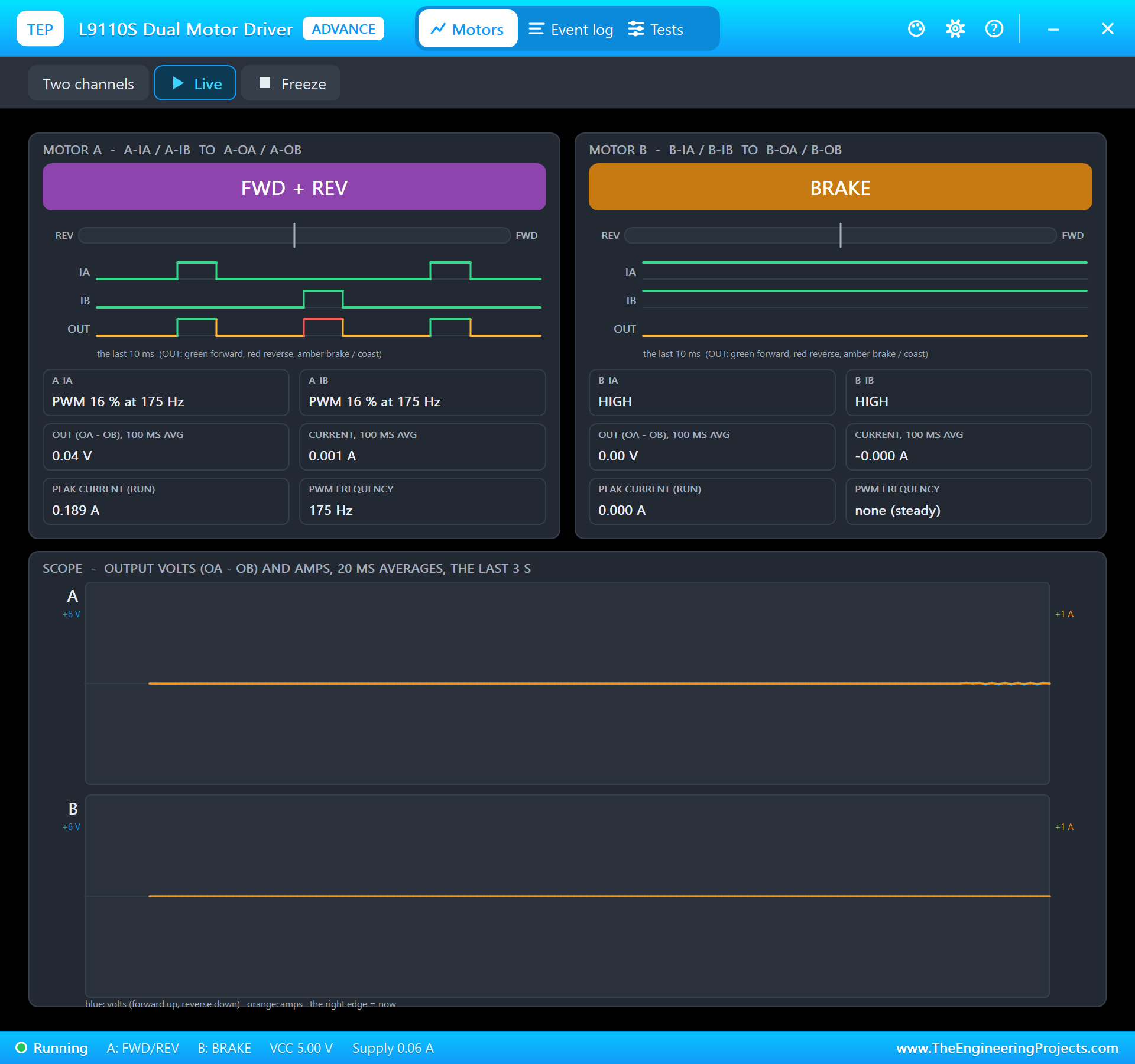
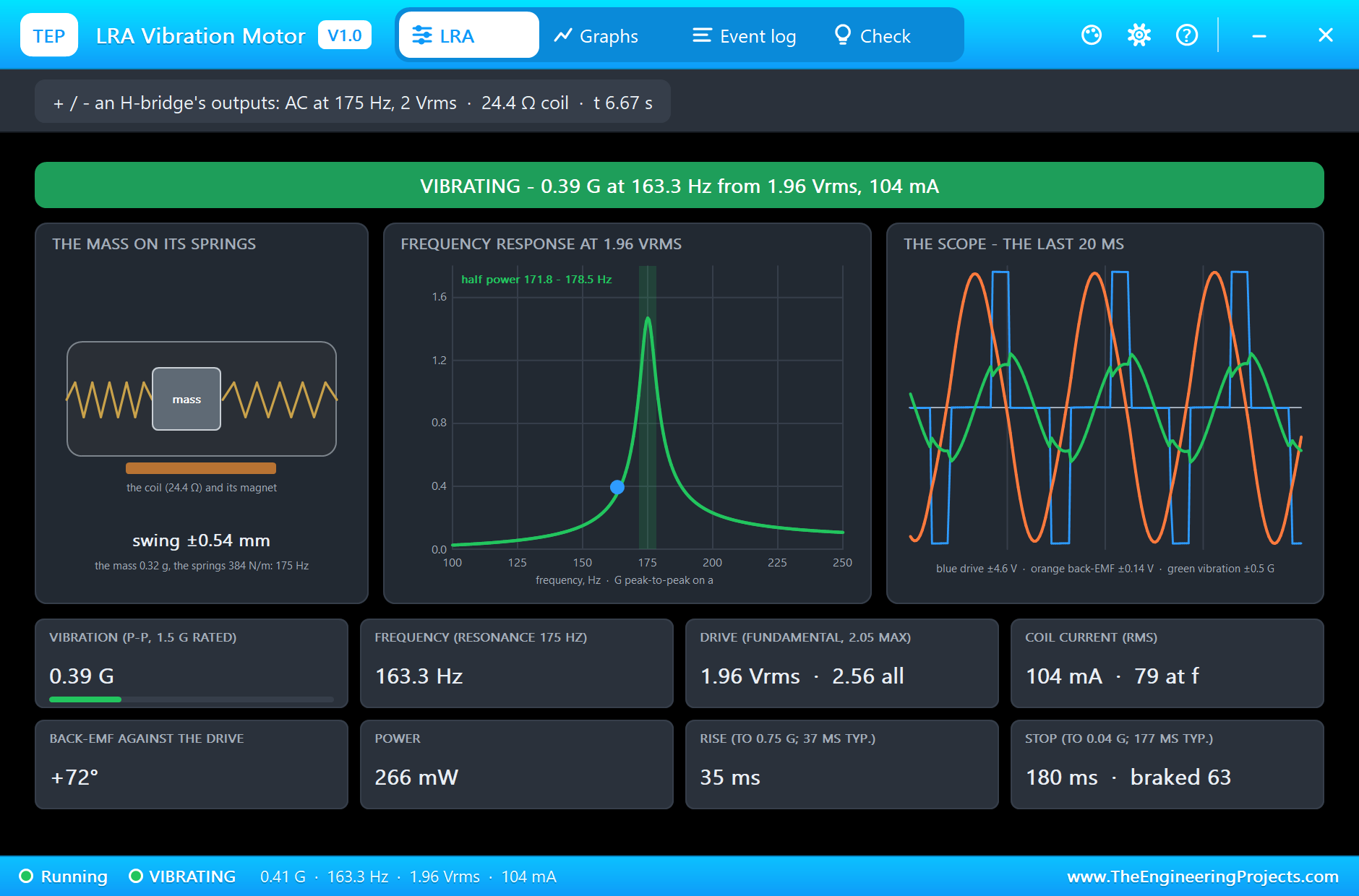
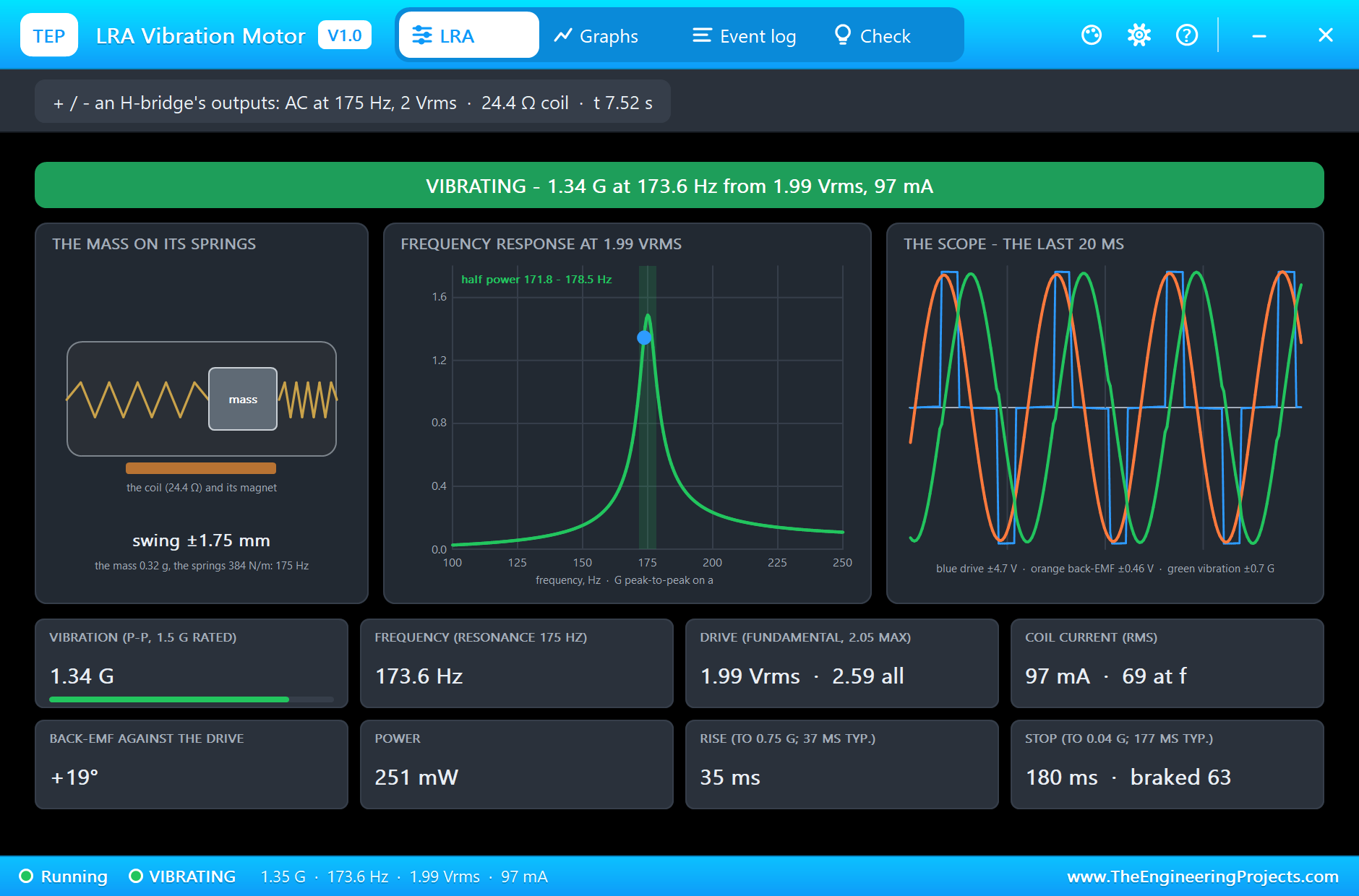
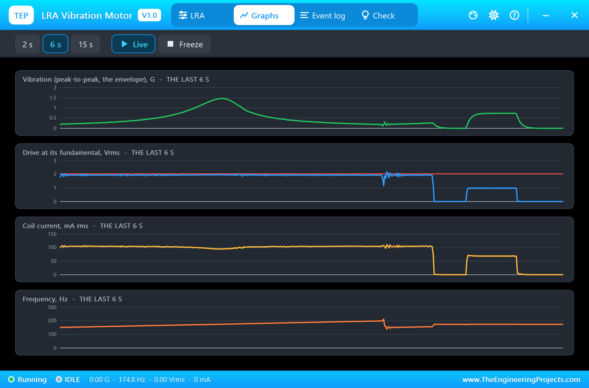
At 2.5 s the sketch plays 175 Hz at 2 Vrms, the rated drive. The pop-up says VIBRATING: 1.47 G peak-to-peak on the 100 g mount from 1.98 Vrms at 175.0 Hz, close to the datasheet's typical 1.5 G at 2 Vrms. The mass swings ± 1.91 mm and the back-EMF is only 3 degrees from the drive: at resonance they are in step. The coil draws 94 mA RMS, but only 66 mA of it is at 175 Hz (the datasheet says 67 mA); the rest is the harmonics of the three-level wave, which heat the coil without shaking the mass. That is one reason haptic driver chips use a sine-like drive.
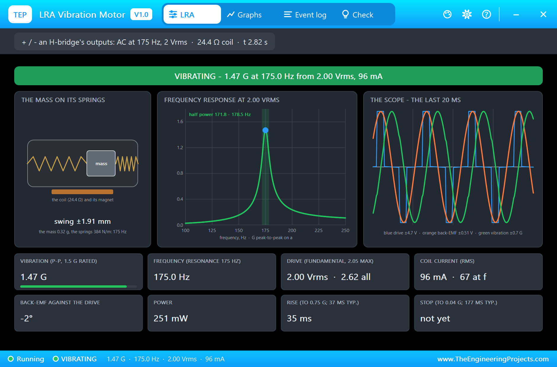
On the sheet, rings round the can grow with the vibration. The scope in the pop-up shows the three-level drive in blue, the back-EMF in orange and the vibration in green, each on its own scale.
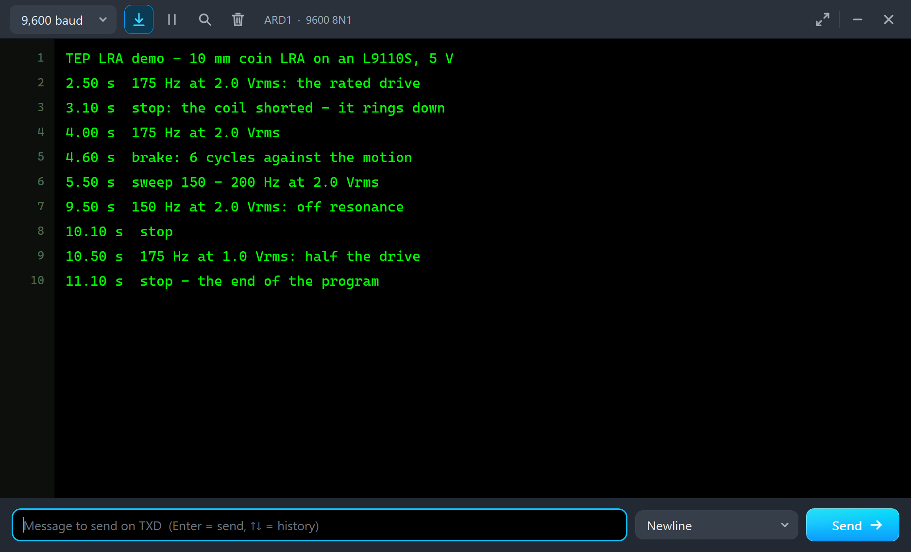
The L9110S's own pop-up shows the same moment from the driver's side: the two inputs switching at 175 Hz and the current through the bridge.
Rise, Stop and the Active Brake
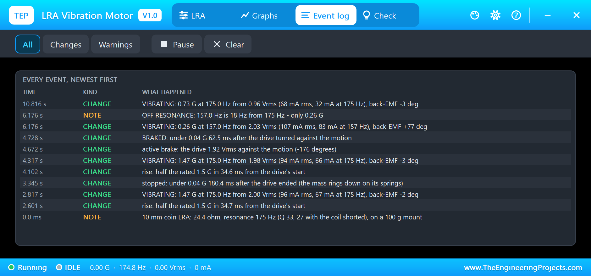
The pop-up times every burst. From the start of the drive, the vibration reaches half the rated 1.5 G in 34.7 ms; the datasheet gives 37 ms. When the sketch stops at 3.1 s, both outputs go low and short the coil, and the mass rings on its springs: it takes 180.4 ms to fall under 0.04 G, against 177 ms in the datasheet. A resonance with a high Q stores energy, so it keeps buzzing after you let go.
At 4.6 s the sketch brakes instead: for 6 cycles the wave pushes against the motion, then it stops. The Event log writes BRAKED: under 0.04 G 62.5 ms after the drive turned against the motion. That is almost three times faster than letting it ring down, and it is why haptic drivers brake every click.
A Sweep Through the Resonance
From 5.5 s the sketch sweeps the frequency from 150 to 200 Hz in 4 seconds at the same 2 Vrms. At 163.7 Hz the LRA gives only 0.40 G, and the back-EMF runs 71 degrees ahead of the drive: below resonance the springs dominate. At 173.5 Hz it climbs to 1.32 G and the phase closes to 21 degrees. The best of the whole run is 1.48 G at 175.0 Hz. The green curve in the pop-up is the model's frequency response at the present drive, with the half-power band shaded and the working point in blue.
Off Resonance and Half the Drive
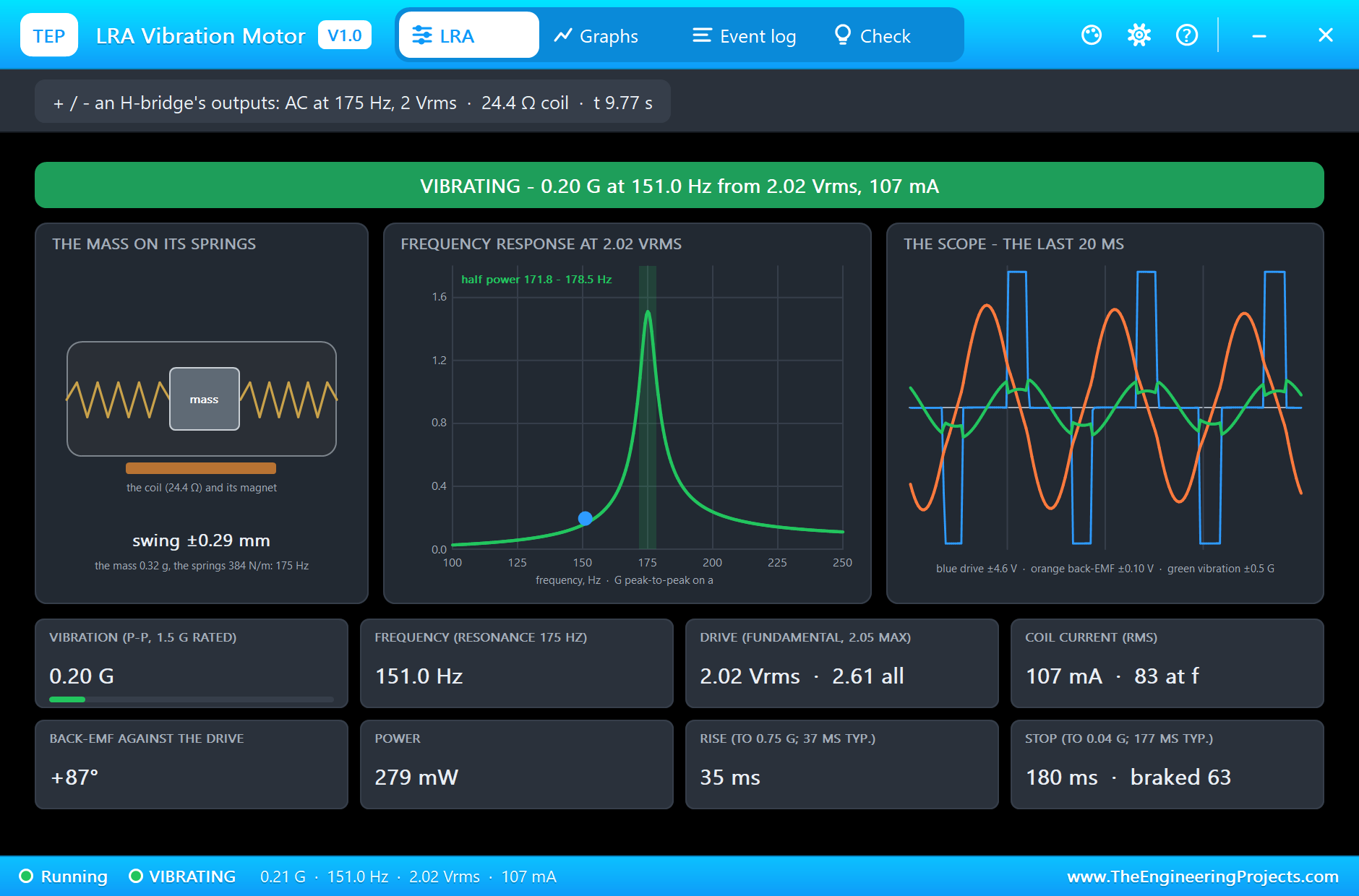
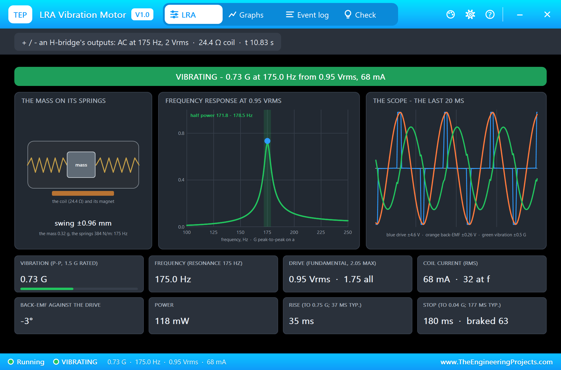
At 9.5 s the sketch plays 150 Hz at the full 2 Vrms. The LRA barely moves: 0.20 G, and the Event log notes OFF RESONANCE. The same drive gives seven times less vibration 25 Hz away. At 10.5 s the sketch goes back to 175 Hz with half the drive, 1.00 Vrms, and the vibration halves too: 0.74 G. At resonance the LRA is linear: the vibration follows the drive.
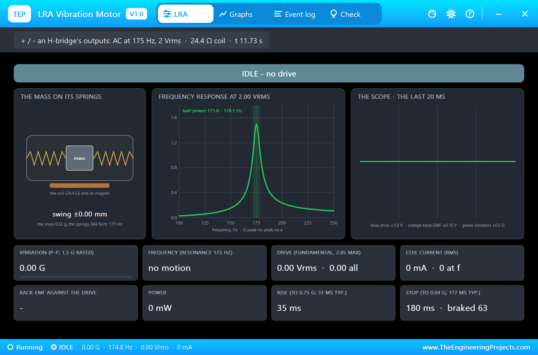
At the end the tiles keep the measured rise, stop and braked stop.
The Graphs, the Event Log and the Check Page
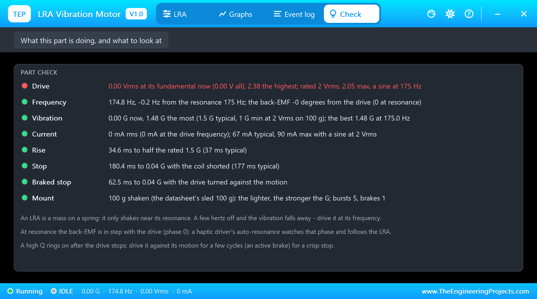
The Graphs page plots the vibration envelope, the drive at its fundamental, the coil current and the frequency over the last 2, 6 or 15 simulated seconds; the sweep draws the resonance curve in time. The Event log keeps every burst with its rise, the steady vibration with its current and phase, the brake and every stop. The Check page compares the run with the datasheet.
Try It Yourself
- Set F0 to 168 Hz (a part at the low end of its spread) and run the demo: the fixed 175 Hz drive now gives much less, and the sweep peak moves.
- Type
f 170, thenf 180: watch the vibration fall on both sides of the peak. - Type
v 1.0andv 2.0at 175 Hz: the vibration follows the drive. - Set MOUNT to 30 g, like a wristband: the same LRA shakes it more than three times harder.
- Change the brake in the sketch from 6 to 3 or 10 cycles: too short leaves a ring, too long starts it again the other way.
Ideas to Extend the Demo
- Make your own auto-resonance: let the drive go briefly, read the back-EMF zero crossings and lock the frequency on them.
- Play haptic effects: short bursts with a brake for clicks, longer ones for buzzes, ramps for transitions.
- Replace the L9110S with our DRV2605L haptic driver library, which finds the resonance and brakes by itself.
Your Own Sketches
The demo sketch is in the zip file, and you can change it in the Arduino IDE. New to Arduino? Start with our Arduino Tutorial for Beginners. Export the compiled binary, and set the UNO's PROGRAM property to the new file. Our guide on How to get the HEX file from Arduino shows you where the file ends up.
Things to Know Before Using a Real LRA
- Find its resonance: a real part may sit several hertz from its rating; a haptic driver with auto-resonance finds it for you.
- Keep under 2.05 Vrms: and prefer a sine-like drive; a square drive heats the coil more for the same vibration.
- Never leave DC on it: a steady voltage only holds the mass aside and heats the coil.
- Fix it firmly: the vibration reaches your hand through the mounting; a loose LRA rattles and feels weak.
Troubleshooting
- Hardly any vibration: the drive is off the resonance; a few hertz matter, the response is only about 6.5 Hz wide.
- DC on the coil: a steady voltage holds the mass aside and does not shake it; drive AC.
- OVER-DRIVEN: more than 2.05 Vrms at the fundamental.
- It buzzes on after the drive stops: the springs ring; brake it with a few cycles against the motion.
- The part is not simulated:
TEPLRA10.DLLis missing from MODELS and from the project folder.
Limitations of the Simulation
- The coil's inductance (85.8 µH, about 0.1 ohm at 175 Hz) is left out.
- The springs do not age or drift with temperature, and the mass does not hit end stops when over-driven.
- The mount is one rigid mass; real cases flex and add their own resonances.
- Arduino is a name of Arduino; this library is not made or endorsed by Arduino, Labcenter or any LRA maker.
- Tested in Proteus 8.5 in November 2026 (the demo as shipped). Proteus 7 is not supported.
So, that was all about the LRA Vibration Motor Library for Proteus Simulation. I hope it helps you understand why an LRA feels so different from a spinning coin motor: a mass on a spring that only answers at its resonance, rings on unless you brake it, and tells you where it is through its back-EMF, all in a simulation with a pop-up that shows the swing and the curve. If you have any questions, ask in the comments and I will help you out. Till the next tutorial, take care and have fun!

Comments
0