


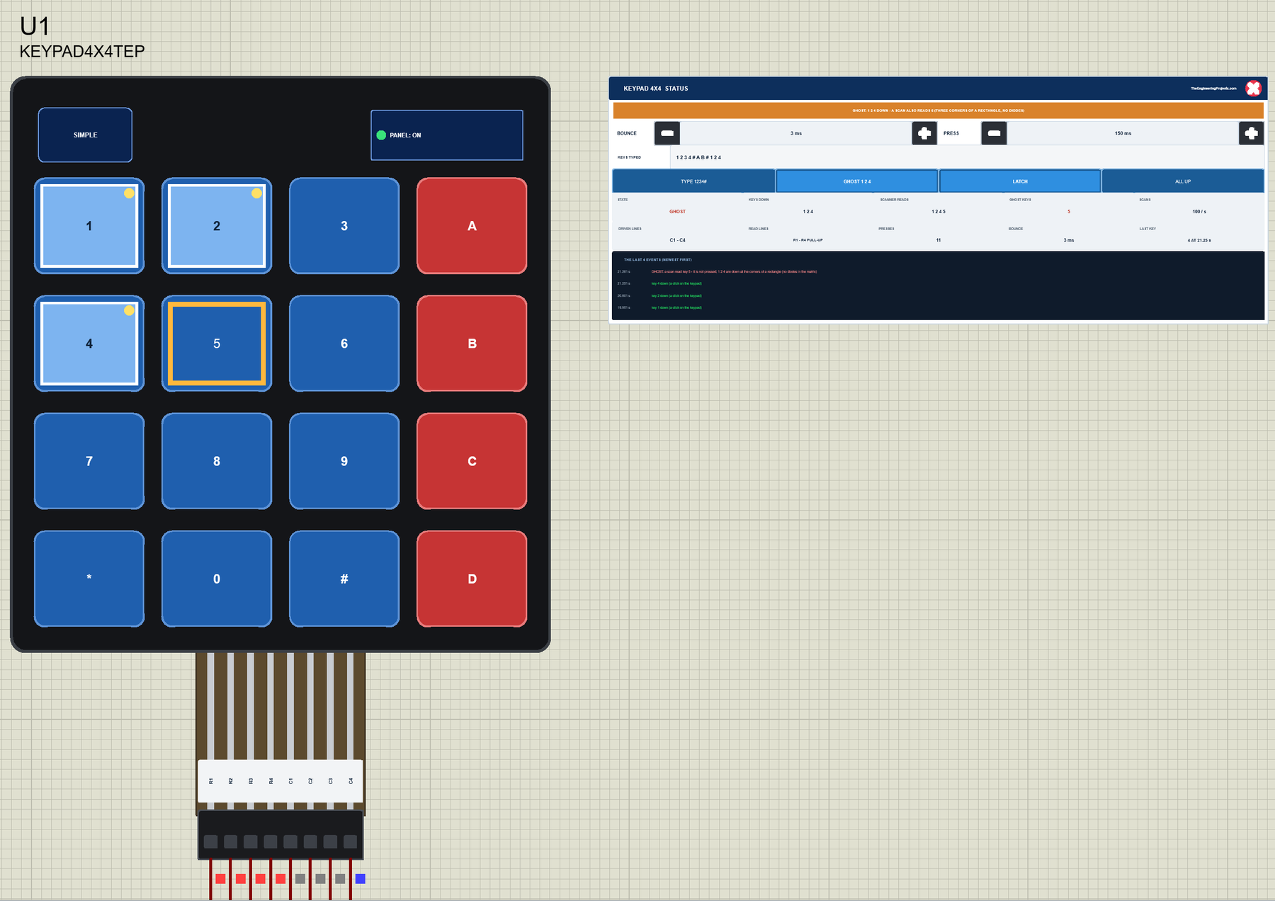
Membrane Keypad Library for Proteus V1.0: 4x4 and 4x3 with Arduino


Hello friends, I hope you all are doing great. Today, I am going to share the new Membrane Keypad Library for Proteus V1.0. The thin, self-adhesive 4x4 and 4x3 membrane keypads are the cheapest way to give an Arduino project a real keypad: a door lock with a code, a menu, a calculator, a safe, a parcel box or a machine that asks for a number. Each comes with a flat ribbon and a female 2.54 mm connector - 8 pins for the 4x4, 7 for the 4x3 - and plugs straight into the Arduino's headers.
Behind the parts sits our own model of a key matrix. You click the keys on the keypad while the simulation runs, and the model behaves like the real contacts under the membrane: a key joins its row line to its column line, and the sketch has to scan the matrix to find it. Because there are no diodes, three keys pressed at the corners of a rectangle make a fourth key read as pressed - the famous ghost key - and each contact bounces for a few milliseconds, so a sketch that scans too fast types one key twice. You get a Simple device with a live STATUS panel and an Advance device with a pop-up window that draws every line through the last scan, microsecond by microsecond. The demo runs on our Arduino UNO V4.0.
NOTICE: a keypad is easy to fake: a part that sends the key you click straight to the sketch. We wanted more. Our keypad sends nothing - it only joins two wires while a key is down, exactly like the real membrane, so a sketch that forgets the pull-ups, swaps rows and columns, scans too fast or too slowly, or meets three keys at once fails exactly as it does on a real keypad. It took our team a lot of hard work. Your feedback is the fuel that keeps us going, so please tell us what you think in the comments below or in the keypad board of our forum. And if our free libraries help you, you can buy us a coffee. So, let's get started with the Membrane Keypad Library for Proteus V1.0:
What is a Membrane Keypad?
A membrane keypad is a sandwich of thin plastic sheets. The top sheet carries the printed keys, the two inner sheets carry silver traces, and a spacer with a hole under each key keeps them apart. Press a key and the two traces touch through the hole; let go and they spring apart. The traces are laid out as a matrix: on a 4x4 keypad four row lines (R1 - R4) cross four column lines (C1 - C4), and under each key one row meets one column. Sixteen keys need only eight wires.
| 4x4 membrane keypad | 4x3 membrane keypad | |
|---|---|---|
| Keys | 1 - 9, 0, *, #, A, B, C, D | 1 - 9, 0, *, # |
| Pins (left to right) | R1 R2 R3 R4 C1 C2 C3 C4 | R1 R2 R3 R4 C1 C2 C3 |
| Inside | a contact under each key, no diodes, no pull-ups | the same |
| Power | none - the keypad only joins wires | none |
| Connector | a flat ribbon with a female 2.54 mm header | the same |
Some 4x3 keypads use another pin order. If yours behaves strangely, check it with a meter: each key joins exactly one row pin to one column pin.
How a Sketch Reads the Keys
The keypad cannot tell the Arduino which key is down; the sketch has to find out. It sets the four row pins as inputs with their internal pull-ups, so they read HIGH. Then it drives one column LOW at a time and reads the rows: a row that reads LOW has a key down in that column. After the last column it starts again. This is a scan, and the popular Keypad library does exactly this: rows with INPUT_PULLUP, one column OUTPUT LOW, the rows read, the column back to HIGH and INPUT, a new scan every 10 ms.
Ghost Keys and Bounce
Two effects come with every matrix keypad. Ghosting: hold 1, 2 and 4 together. When the scan drives C2 LOW, row R1 goes LOW through key 2, column C1 follows through key 1, and row R2 follows through key 4 - so the scan reads R2 LOW while C2 is driven, which is key 5. Three keys at the corners of a rectangle make the fourth corner read as pressed. Only a diode under each key would stop it, and membrane keypads have none. Bounce: a contact does not close cleanly; it closes and opens a few times in the first milliseconds, and again when it opens. A sketch that scans every 10 ms never notices; one that scans every millisecond can read one press as two.
What's New in Membrane Keypad Library for Proteus V1.0
- Clickable keys: click a key on the keypad while the simulation runs - it is down while the mouse button is, at least PRESS ms (150 by default).
- A real matrix: the model joins a key's row and column while it is down and drives nothing else, so any scanning sketch or library works.
- Ghosting and bounce: three keys at the corners of a rectangle make a ghost; each contact bounces for BOUNCE ms (3 by default).
- The scanner seen from the keypad: which lines the sketch drives, which it reads with pull-ups, the scans a second, presses a scan saw or missed, ghost keys a scan read, outputs shorted through the keys.
- Four actions: TYPE 1234#, GHOST 1 2 4, LATCH (a click puts a key down, the next lifts it) and ALL UP.
- The last scan in the Advance pop-up: every line through one scan, microsecond by microsecond.
- Three test tools on the Advance devices: Matrix & wiring, Keys & timing, and Ghosting.
- A two-node demo on our Arduino UNO V4.0 with no library: a 4x4 and a 4x3 keypad on the same sketch, a code lock, and the CODE, SCAN and MULTI commands.
- A compact package: about 1.25 MB, without the C++ source code of the model.
Four Devices: Simple and Advance
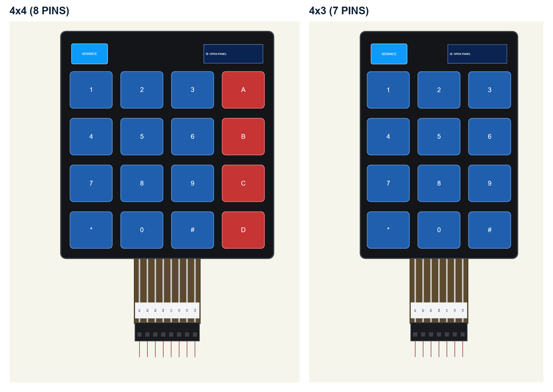
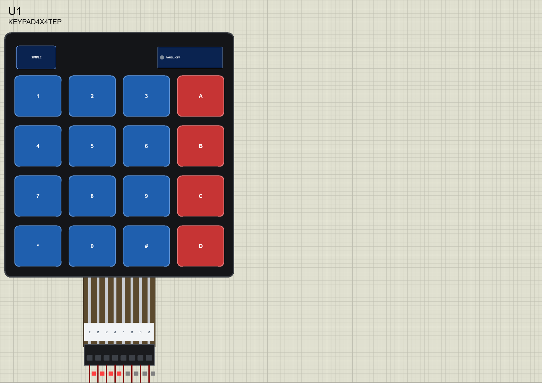
Each part shows the black membrane with its keys - on the 4x4, A, B, C and D in red - the ribbon with its silver conductors and the black connector at its end. The pins point down, left to right R1 R2 R3 R4 C1 C2 C3 C4, and a white label on the ribbon names them. The SIMPLE / ADVANCE badge, the panel button above the keys and the label are TEP additions.
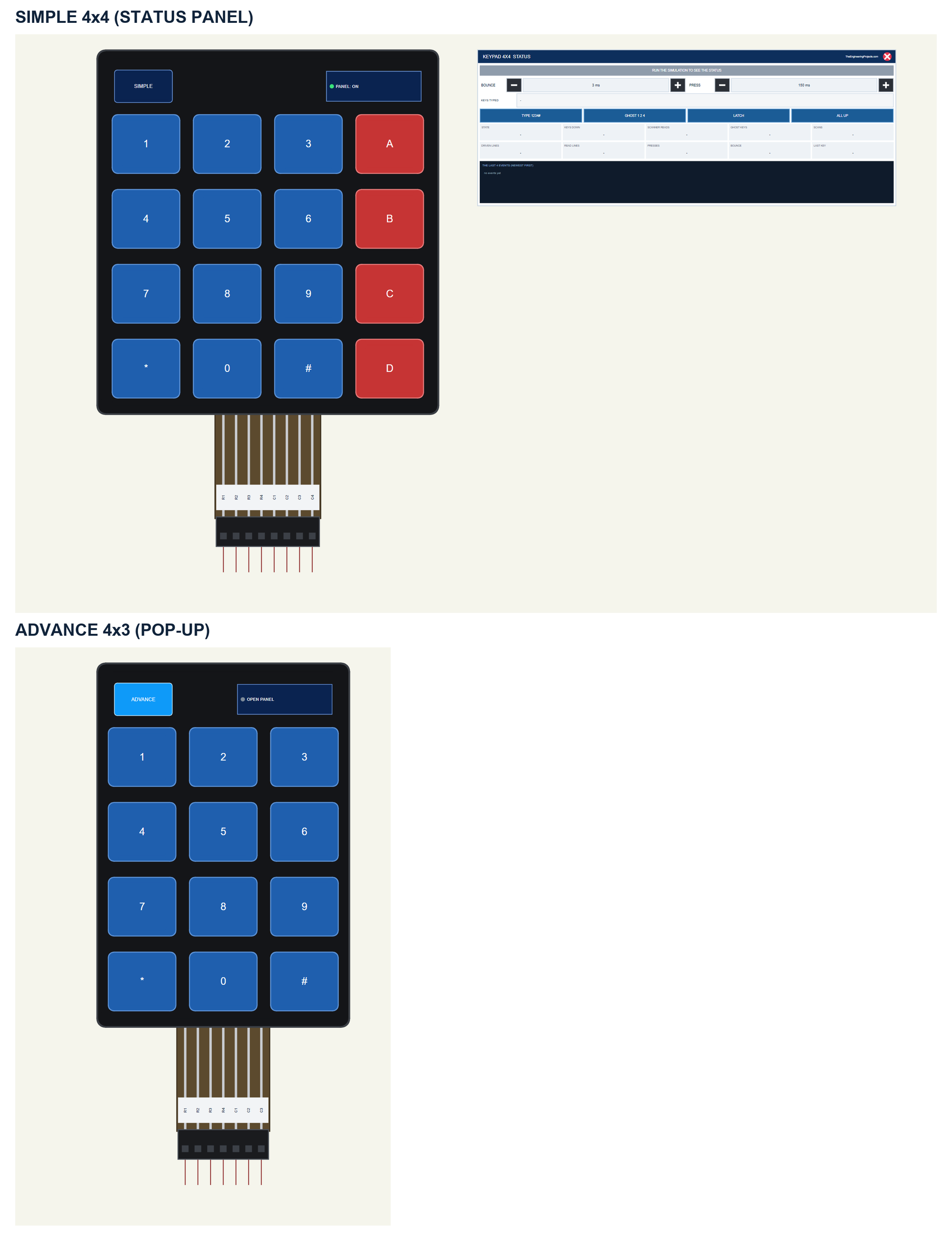
| Simple | Advance | |
|---|---|---|
| 4x4 keypad | KEYPAD4X4TEP | KEYPAD4X4ADVTEP |
| 4x3 keypad | KEYPAD4X3TEP | KEYPAD4X3ADVTEP |
| On the schematic | The keypad and the STATUS panel | The keypad |
| The keys | Clickable on the keypad | Clickable on the keypad and in the pop-up |
| Status | Banner, 10 readouts, the last 4 events | A pop-up: Keypad, Event log, Tests |
Download Membrane Keypad Library for Proteus
Click the button below to download Membrane-Keypad-Library-for-Proteus-v1.0.zip (about 1.25 MB, without the C++ source code of the model):
Membrane Keypad Library for Proteus V1.0- README.txt: the devices, installation, the demo, wiring, the test tools and real hardware.
- Proteus Library Files:
TEPKEYPAD.LIBandArduinoV4TEP.LIBfrom our Arduino Library for Proteus V4.0. - Proteus Model Files:
TEPKEYPAD.DLLandTEPARDUINO.DLL. - Proteus Simulation:
Membrane-Keypad-ArduinoUnoV4.pdsprj,Membrane_Keypad_Demo.hexand copies of the two DLLs. - Arduino Code:
Membrane_Keypad_Demo.ino- it needs no library.
No Proteus yet? Read How to Download and Install Proteus 7 and 8. New to libraries? Follow How to Install a New Library in Proteus.
How to Install Membrane Keypad Library for Proteus
- Close Proteus and extract the whole zip file, for example to your Desktop.
- Copy the two files from Proteus Library Files into the LIBRARY folder of Proteus (usually
C:\Program Files (x86)\Labcenter Electronics\Proteus 8 Professional\LIBRARY). - Copy
TEPKEYPAD.DLLandTEPARDUINO.DLLfrom Proteus Model Files into the MODELS folder. - Delete
TEPKEYPAD.IDXfrom the LIBRARY folder if it is there. - Start Proteus, press P and search for KEYPAD.
Tip: keep the Proteus Simulation folder together, because the project needs its .hex file and the DLLs beside it. The library is tested in Proteus 8.5; Proteus 7 is not supported.
The Membrane Keypad Part in Proteus
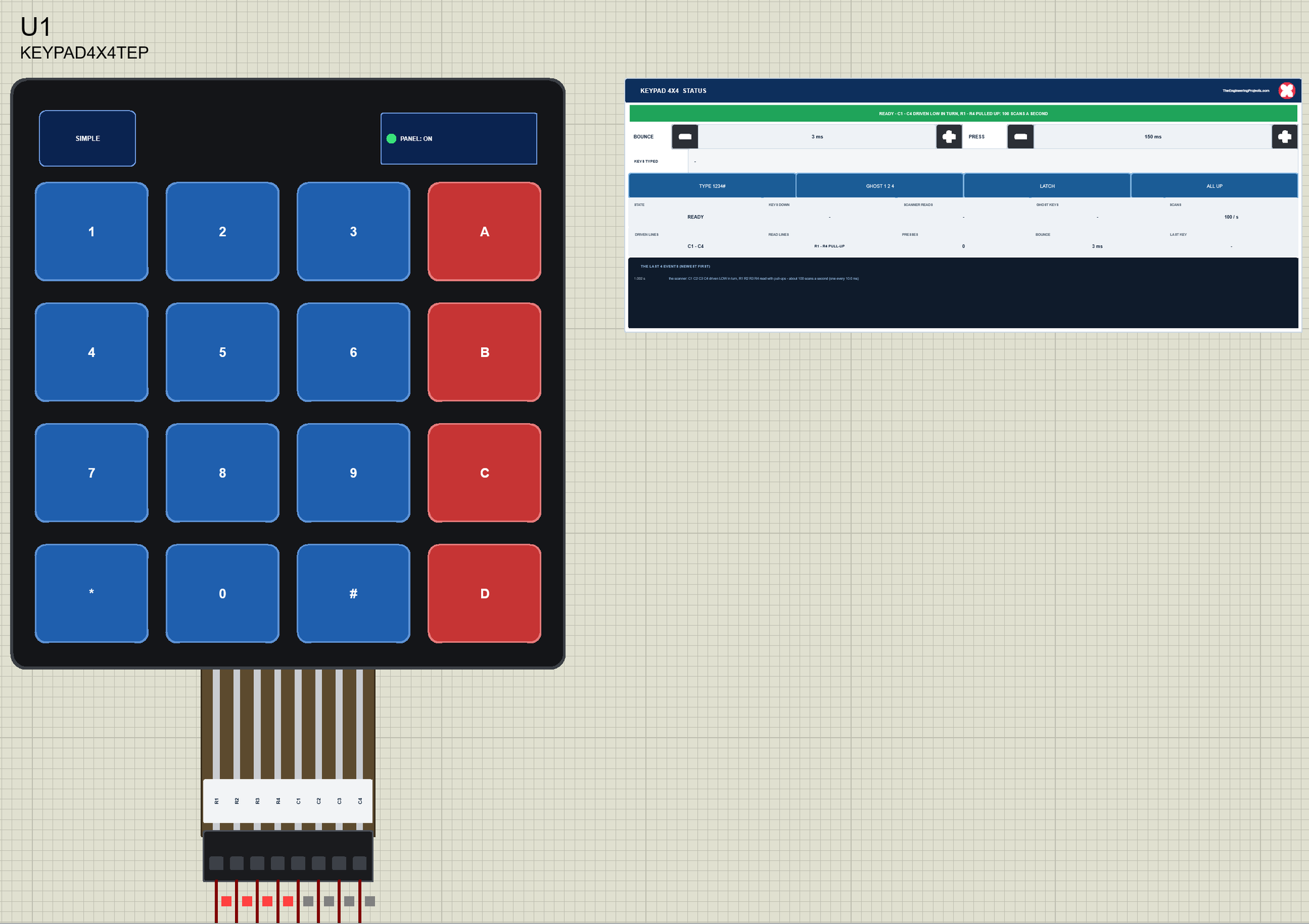
The Simple device adds the STATUS panel beside the keypad. Its banner says what the scan reads: green when all is well; amber for ghost keys, a scan faster than the bounce, or rows and columns swapped in the sketch; red when no line is driven LOW in turn or the rows float without pull-ups; blue in LATCH mode; grey while the first scans come. Below it are - and + for BOUNCE (1 ms a click) and PRESS (50 ms a click), the keys typed, four actions, ten readouts and the last four events.
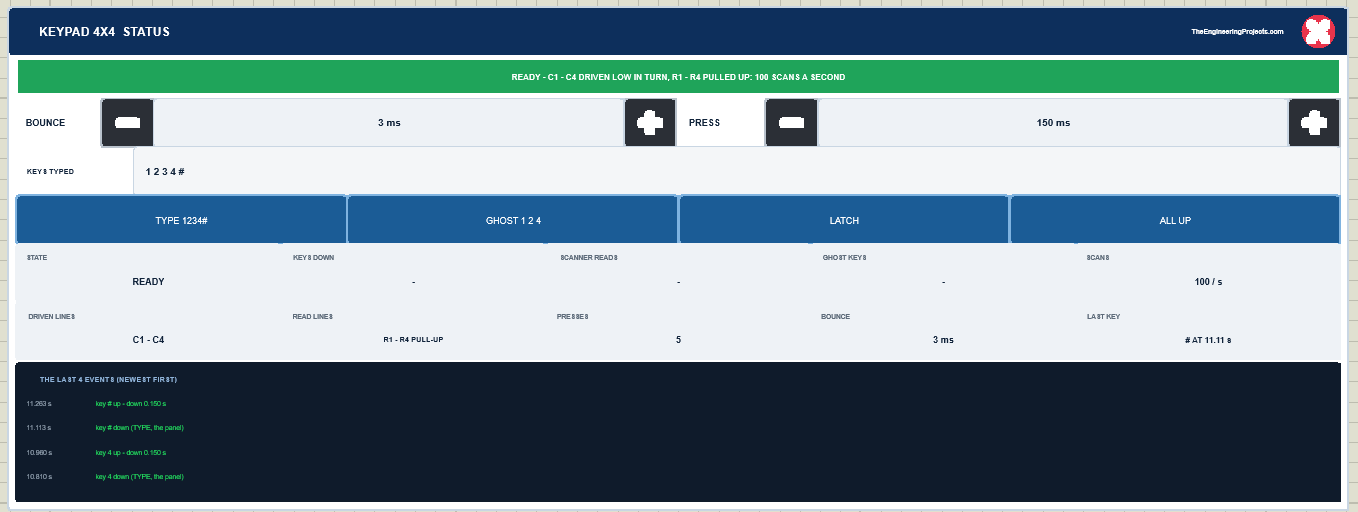
The readouts are the state, the keys down, what the scan reads, the ghost keys, the scans a second, the driven lines, the read lines, the presses, the bounce and the last key. The actions: TYPE 1234# presses 1, 2, 3, 4 and # one after the other, each for PRESS ms; GHOST 1 2 4 holds 1, 2 and 4 down together, and a second click lets them go; LATCH changes what a click does - a click puts a key down and the next click lifts it, so you can hold several keys with the mouse; ALL UP lifts every key. You can always click the keys of the keypad itself. The red X closes the STATUS panel, and the PANEL button opens it again:
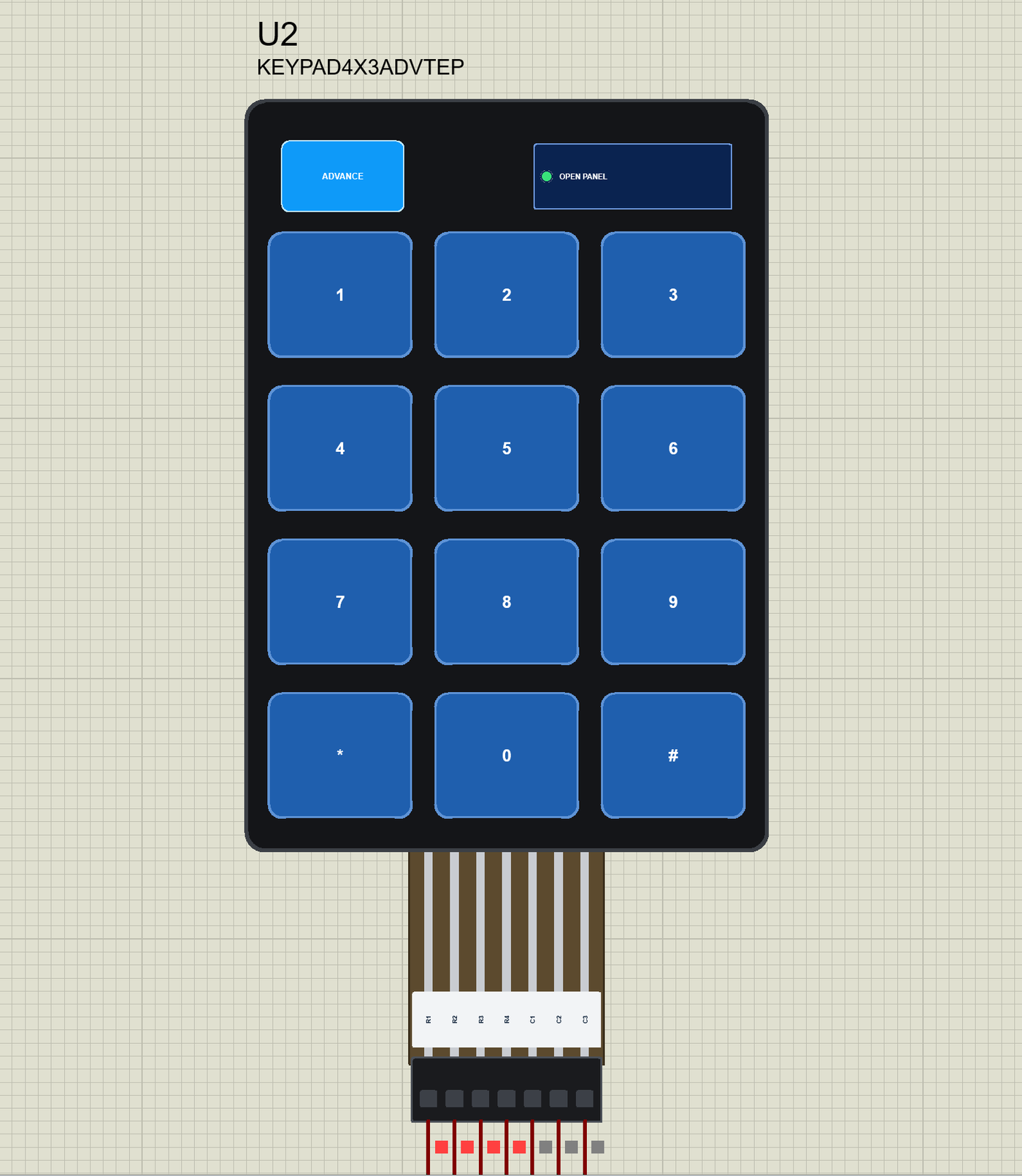
The Advance devices keep the schematic clean: only the keypad. The live data opens in a pop-up window at Run, and the OPEN PANEL button on the membrane brings the window back. Their keys can be clicked on the schematic too:
The properties set the start: BOUNCE, the contact's bounce in ms (3), and PRESS, the shortest press of a click in ms (150). The Simple devices also have PANEL (open or closed). Every run starts again from the properties.
The Demo Circuit
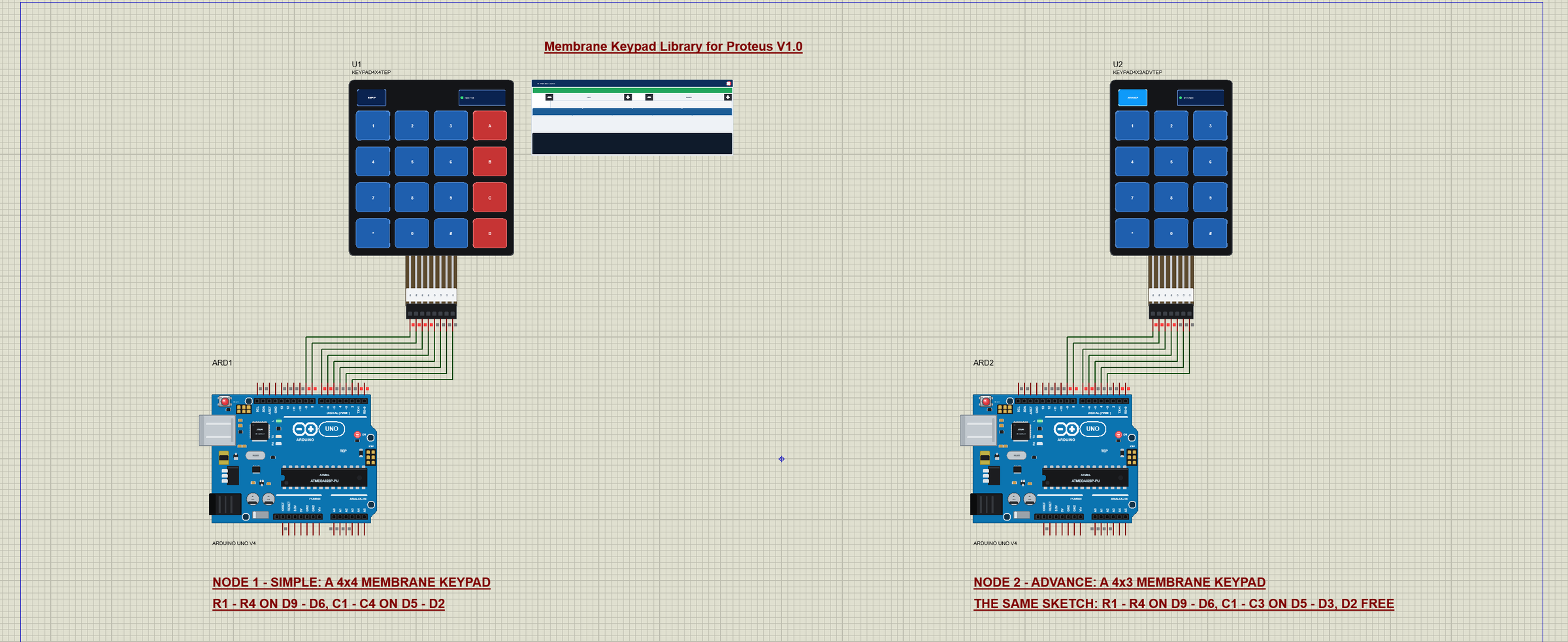
The demo project has two nodes, each an Arduino UNO V4.0 from our Arduino UNO Library for Proteus V4.0 with a keypad wired straight to its digital pins. Node 1 has the 4x4 keypad, node 2 the 4x3. Both UNOs run the same Membrane_Keypad_Demo.hex: the 4x3 keypad simply leaves D2, the fourth column, unconnected - the sketch still drives it, and nothing answers.
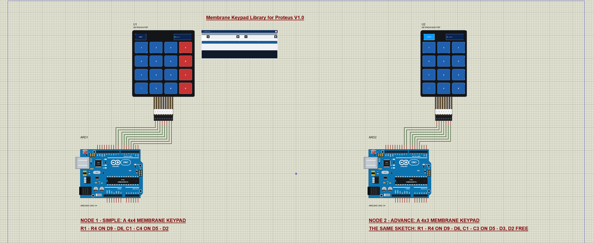
Wiring
| Keypad pin | 4x4 keypad | Arduino UNO (the demo) |
|---|---|---|
| 1 - 4 | R1 - R4 | D9, D8, D7, D6 (INPUT_PULLUP) |
| 5 - 8 | C1 - C4 | D5, D4, D3, D2 (one at a time OUTPUT LOW) |
| 4x3 keypad | R1 - R4, C1 - C3 | D9 - D3; D2 stays free |
In the demo the eight (seven) wires run straight from the keypad's pins to the UNO's top header, in order, so they never cross. The keypad needs no power and no resistors: the UNO's internal pull-ups keep the rows HIGH. The serial monitor needs no wires at all, because it is built into the UNO V4.0.
The Arduino Code
The demo sketch needs no library - it scans the matrix itself, the way the Keypad library does. New to Arduino? Start with Arduino Tutorial for Beginners and Introduction to Arduino UNO. The pins and the keymap:
const byte ROWS = 4, COLS = 4;
const byte rowPins[ROWS] = {9, 8, 7, 6};         // R1 - R4: keypad pins 1 - 4
const byte colPins[COLS] = {5, 4, 3, 2};         // C1 - C4: keypad pins 5 - 8
const char keymap[ROWS][COLS] = {
{'1', '2', '3', 'A'},
{'4', '5', '6', 'B'},
{'7', '8', '9', 'C'},
{'*', '0', '#', 'D'}
};In setup() the rows get their pull-ups and the columns float:
  for (byte r = 0; r < ROWS; r++) pinMode(rowPins[r], INPUT_PULLUP);
  for (byte c = 0; c < COLS; c++) pinMode(colPins[c], INPUT);
One Scan
scan() drives one column LOW at a time and reads the four rows. Afterwards the column goes HIGH and then back to INPUT - floating - as the Keypad library does, so two keys in one row can never short an output LOW to an output HIGH:
void scan(bool now[ROWS][COLS]) {
  for (byte c = 0; c < COLS; c++) {
    pinMode(colPins[c], OUTPUT);
    digitalWrite(colPins[c], LOW);
    for (byte r = 0; r < ROWS; r++)
      now[r][c] = digitalRead(rowPins[r]) == LOW;
    digitalWrite(colPins[c], HIGH);
    pinMode(colPins[c], INPUT);                  // the column floats again
  }
}
loop() scans every scanMs (10 ms at the start) and compares the result with the last scan. A key that reads down now and did not before has just gone down. The time between two scans is also the debounce time: a 3 ms bounce is over long before the next scan comes:
  if (millis() - lastScan >= scanMs) {
    lastScan = millis();
    bool now[ROWS][COLS];
    scan(now);
    bool changed = false;
    for (byte r = 0; r < ROWS; r++)
      for (byte c = 0; c < COLS; c++) {
        if (now[r][c] == down[r][c]) continue;
        changed = true;
        down[r][c] = now[r][c];
        if (now[r][c] && !multi) keyDown(keymap[r][c]);
      }
    if (changed && multi) printHeld();
The Code Lock
keyDown() prints every key with the time. Digits and letters make an entry of up to eight keys, * clears it, and # compares it with the code:
      if (strcmp(entry, code) == 0) Serial.println(F(": correct, unlocked"));
      else Serial.println(F(": wrong"));
The Commands
CODE n sets a new code, SCAN ms the time between two scans (1 - 200), and MULTI 1 prints every change of the keys held instead of one line per key - with a hint when four of them sit at the corners of a rectangle:
  for (byte r1 = 0; r1 < ROWS; r1++)
    for (byte r2 = r1 + 1; r2 < ROWS; r2++)
      for (byte c1 = 0; c1 < COLS; c1++)
        for (byte c2 = c1 + 1; c2 < COLS; c2++)
          if (down[r1][c1] && down[r1][c2] && down[r2][c1] && down[r2][c2]) rect = true;
The HEX file is in the package, so you do not need the Arduino IDE to run the demo. To change the sketch, open it in the Arduino IDE and export the compiled binary, as in How to get the HEX file from Arduino. It needs 6,918 bytes of flash and 335 bytes of RAM.
TYPE 1234#: the Code Lock
At Run, U2 opens its own window, Membrane Keypad 4x3, with the look of our TEP Serial Monitor Advance for Proteus. It has three tabs, Keypad, Event log and Tests, plus Settings and Help behind the gear and question mark icons. We clicked TYPE 1234# on its toolbar:
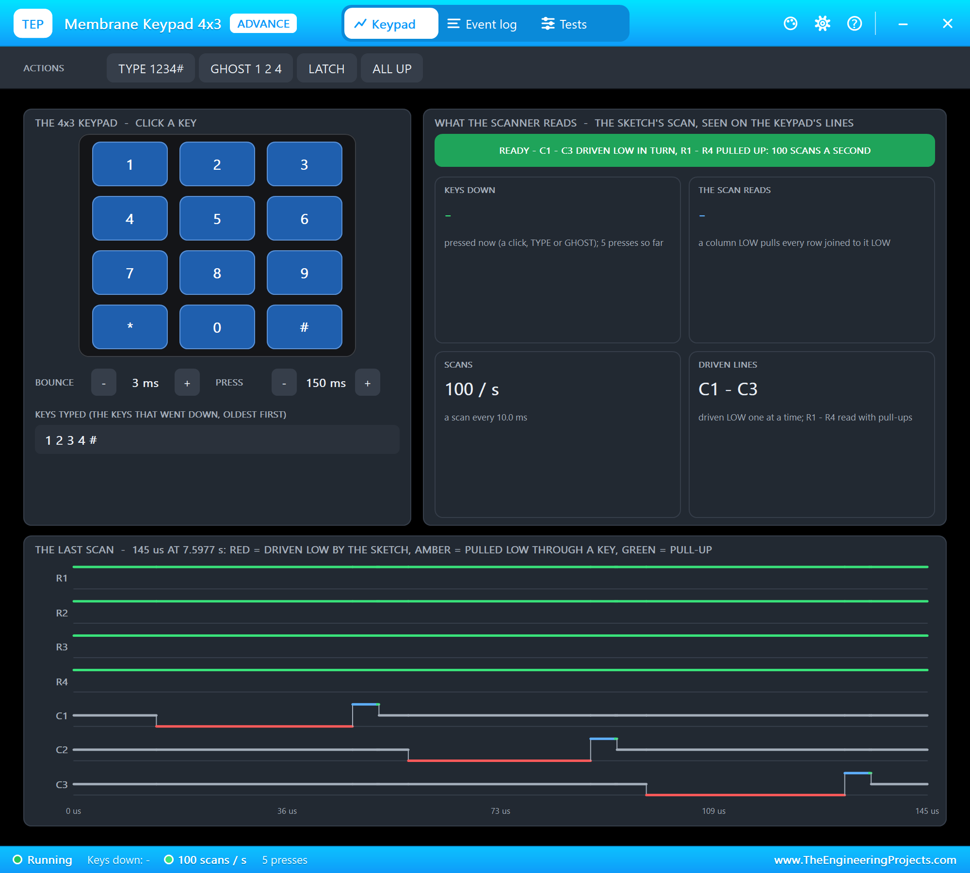
The Keypad page shows the keypad - click its keys -, the BOUNCE and PRESS steppers and the keys typed. What the scanner reads has the banner and four tiles: the keys down, what a scan reads, the scans a second and the driven lines. The last scan draws every line through one scan: red where the sketch drives a line LOW, amber where a key pulls a line LOW with it, green for a pull-up, blue for a line driven HIGH, grey for a floating one. Here C1, C2 and C3 go LOW one after the other, each for about 25 microseconds, while the rows stay HIGH.
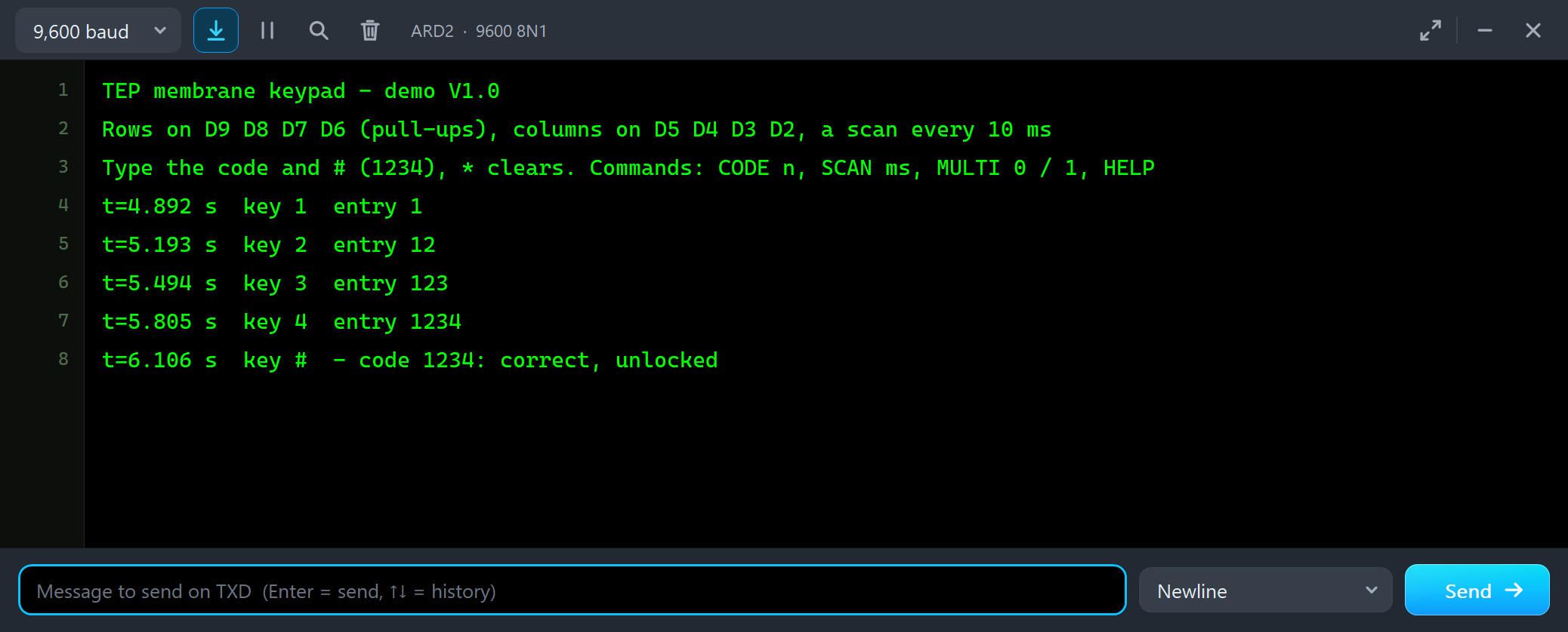
TEP membrane keypad - demo V1.0
Rows on D9 D8 D7 D6 (pull-ups), columns on D5 D4 D3 D2, a scan every 10 ms
Type the code and # (1234), * clears. Commands: CODE n, SCAN ms, MULTI 0 / 1, HELP
t=4.892 s  key 1  entry 1
t=5.193 s  key 2  entry 12
t=5.494 s  key 3  entry 123
t=5.805 s  key 4  entry 1234
t=6.106 s  key #  - code 1234: correct, unlocked
The five keys arrive about 300 ms apart - 150 ms down, 150 ms up - and # checks the entry: code 1234: correct, unlocked. The serial monitor is built into the UNO V4.0 and opens at Run; the screenshots use its Simple interface. Then we clicked 1, 2, 3, 5 and #, then 9 and * on the pop-up's keypad:
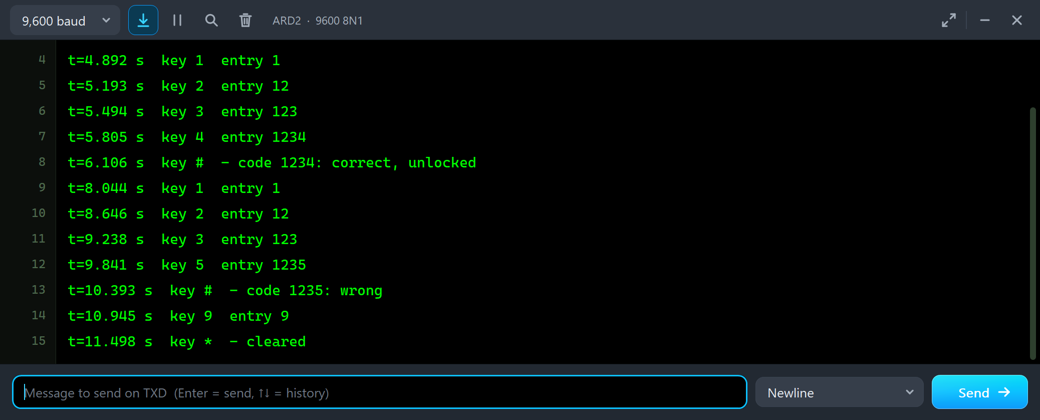
t=8.044 s  key 1  entry 1
t=8.646 s  key 2  entry 12
t=9.238 s  key 3  entry 123
t=9.841 s  key 5  entry 1235
t=10.393 s  key #  - code 1235: wrong
t=10.945 s  key 9  entry 9
t=11.498 s  key *  - cleared
Matrix & Wiring
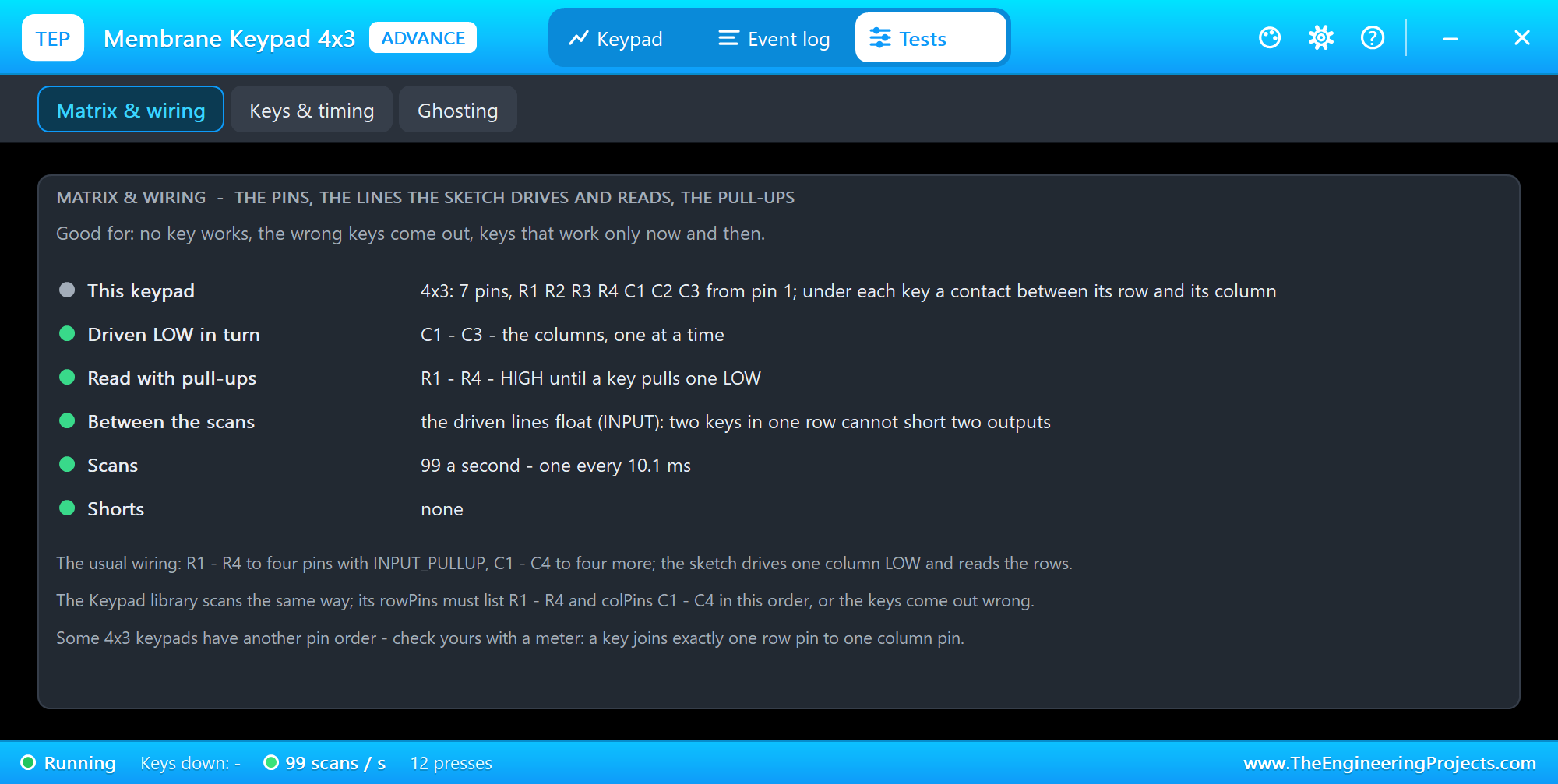
The Matrix & wiring tool shows what the model learns from the lines alone: which lines the sketch drives LOW in turn (the columns here), which it reads with pull-ups (the rows), what the driven lines do between the scans, the scans a second and any shorts. It turns red without pull-ups, amber with rows and columns swapped - the keys would come out transposed - and red when no line is driven at all. Open it first when no key works.
Ghost Keys
Now the famous one. We typed MULTI 1 in ARD2's monitor and clicked GHOST 1 2 4:
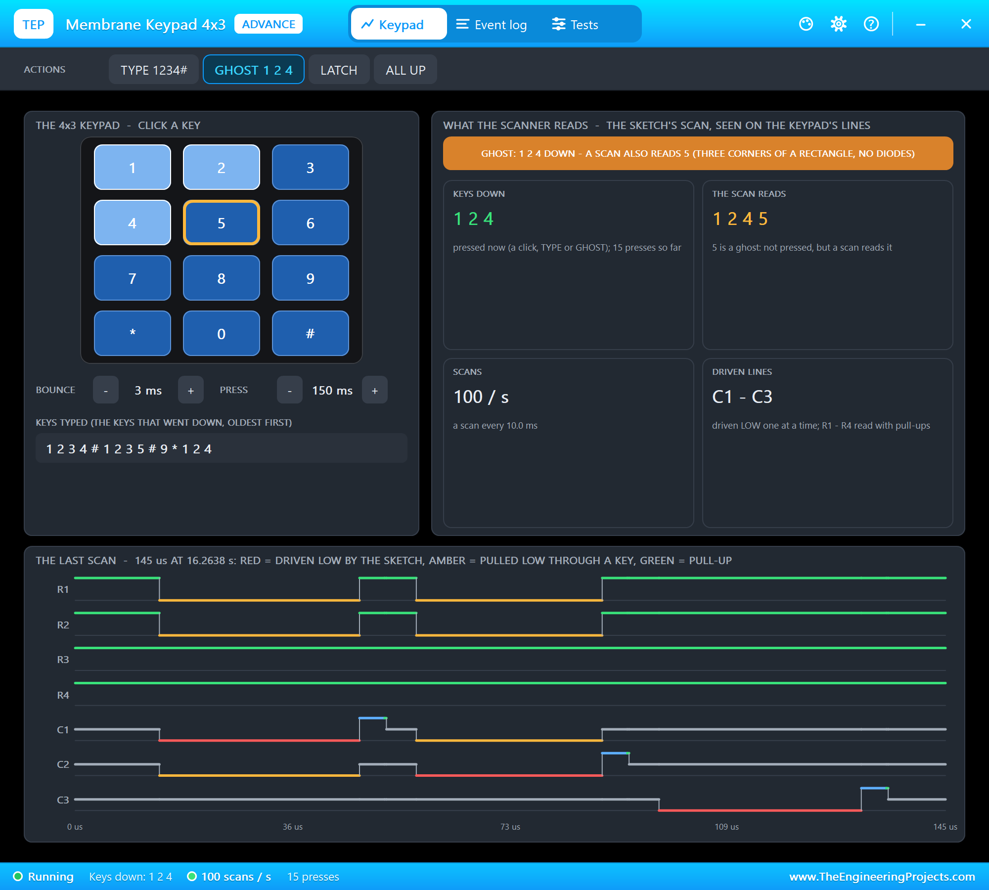
Keys 1, 2 and 4 are down, and the scan reads 1 2 4 5. The last scan shows why: while C2 is driven LOW (red), R1 follows through key 2, C1 through key 1 and R2 through key 4 (amber) - and R2 LOW while C2 is driven is key 5. The banner turns amber, key 5 gets an amber ring, and the model logs that a scan read a key that is not pressed.
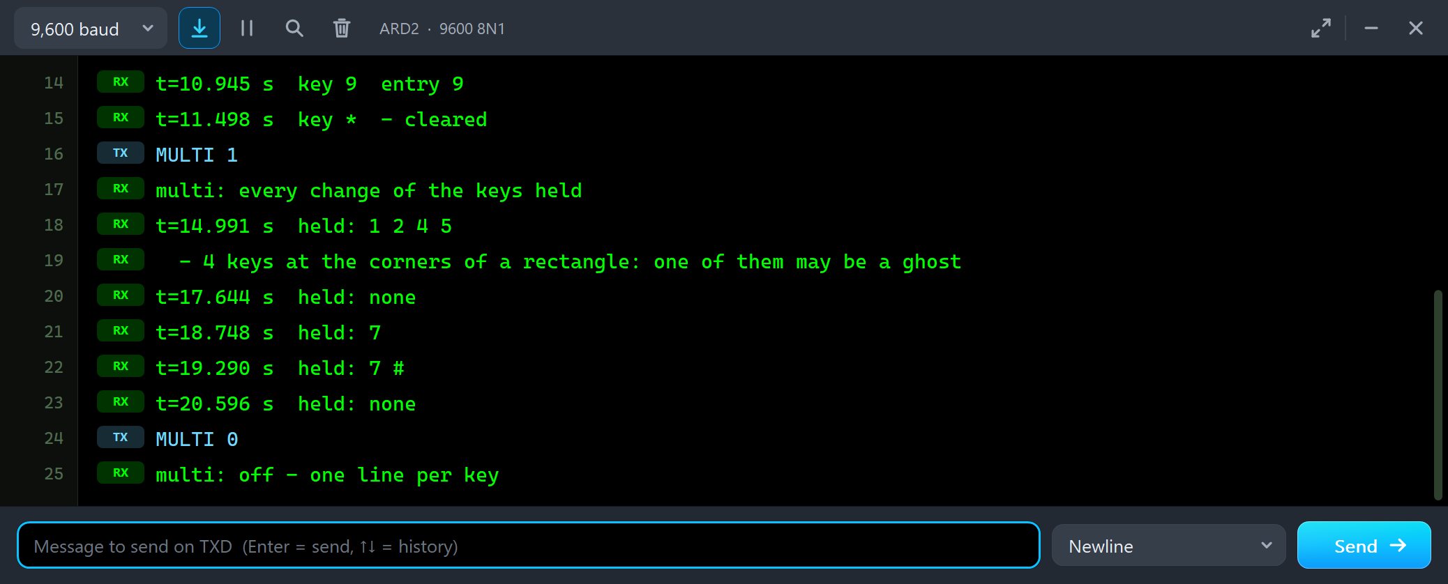
MULTI 1
multi: every change of the keys held
t=14.991 s  held: 1 2 4 5
  - 4 keys at the corners of a rectangle: one of them may be a ghost
t=17.644 s  held: none
t=18.748 s  held: 7
t=19.290 s  held: 7 #
t=20.596 s  held: none
MULTI 0
multi: off - one line per key
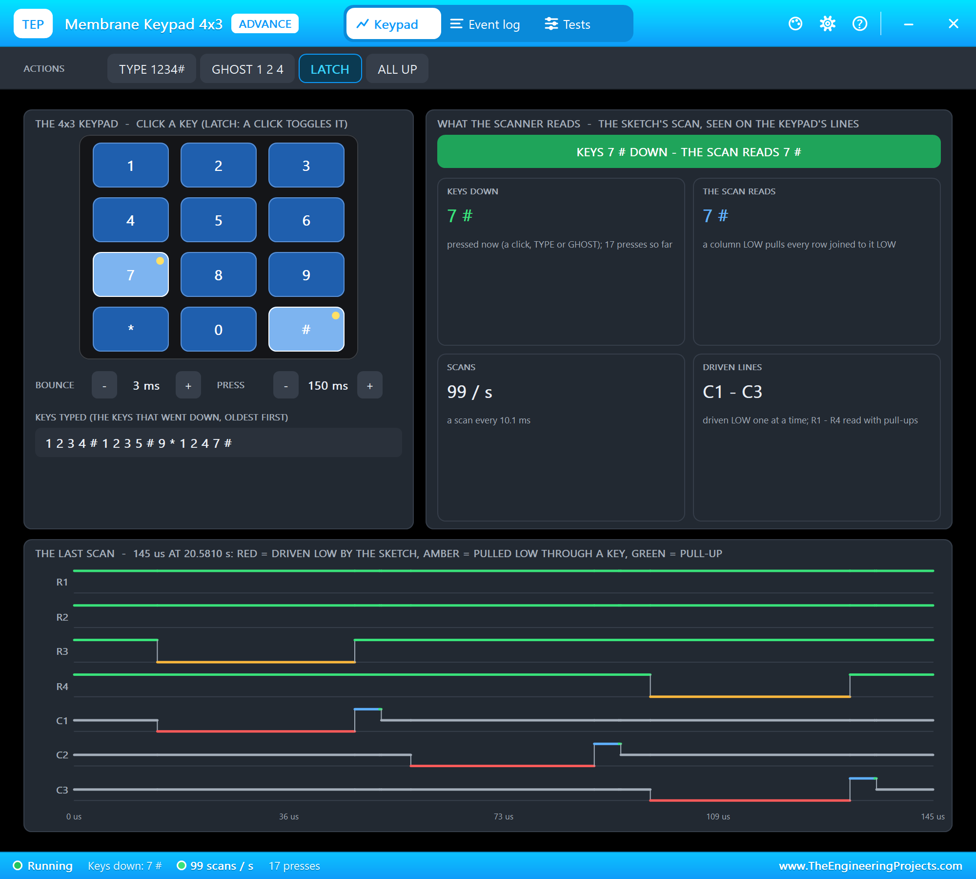
The sketch sees held: 1 2 4 5 - it cannot know that 5 is a ghost, but it can notice that the four keys sit at the corners of a rectangle and warn. Then we switched on LATCH and clicked 7 and #: two keys at once, no rectangle, and the scan reads exactly 7 #:
Ghosting
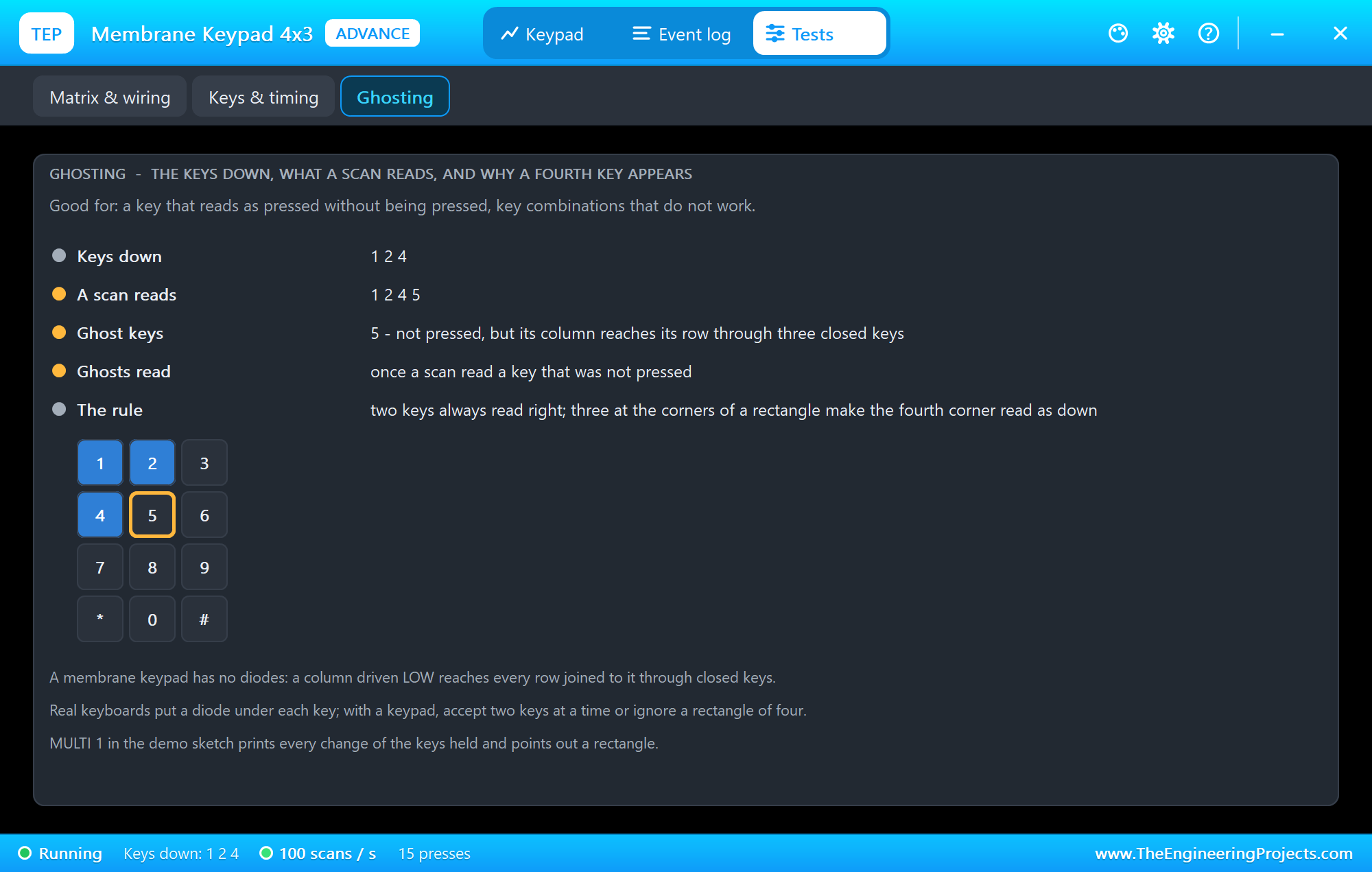
The Ghosting tool lists the keys down, what a scan reads and the ghost keys, and draws the matrix. The rule is simple: two keys always read right; three at the corners of a rectangle make the fourth corner read as down. A real keyboard puts a diode under each key; with a membrane keypad, accept two keys at a time, or ignore a rectangle of four.
SCAN 1: When the Bounce Becomes a Key
Next we typed SCAN 1 - a scan every millisecond - and clicked 8 five times:

t=23.437 s  key 8  entry 8
t=23.439 s  key 8  entry 88
t=23.586 s  key 8  entry 888
t=23.986 s  key 8  entry 8888
t=23.989 s  key 8  entry 88888
t=24.537 s  key 8  entry 888888
t=24.539 s  key 8  entry 8888888
t=25.085 s  key 8  entry 88888888
t=25.089 s  key 8  entry 88888888
t=25.238 s  key 8  entry 88888888
t=25.635 s  key 8  entry 88888888
t=25.638 s  key 8  entry 88888888
Five presses, twelve "key 8" lines. Look at the times: pairs 2 - 4 ms apart are the bounce when the key goes down - the contact closes, opens again for a moment, closes - and lines about 150 ms after a press are the bounce when it comes up, read as a new press. With a scan every millisecond the sketch sees every flicker; with a scan every 10 ms the next scan comes after the bounce is over. That is why the Keypad library scans every 10 ms by default.
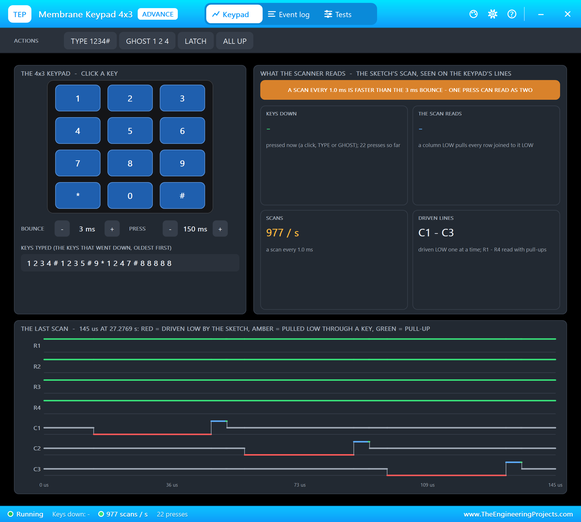
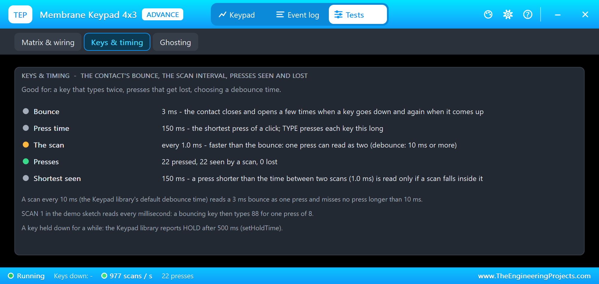
The pop-up counts 977 scans a second and warns, and the Keys & timing tool puts the numbers side by side: the bounce, the press time and the time between two scans.
SCAN 200: Lost Presses
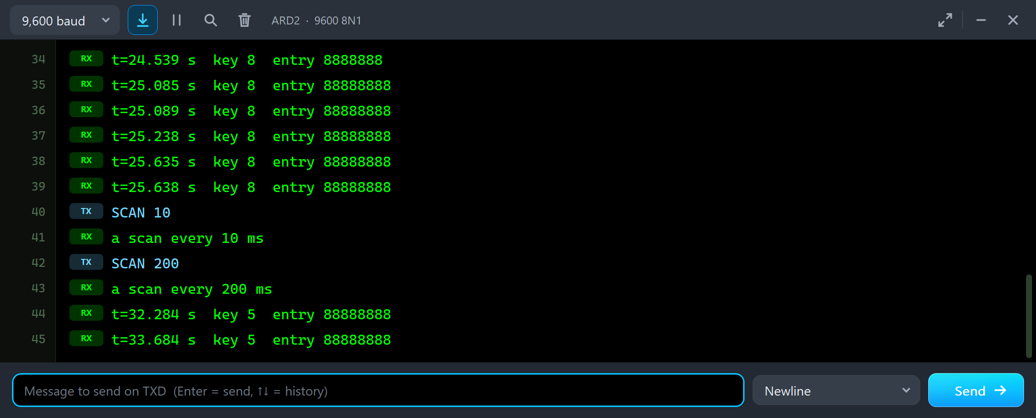
The other way round: SCAN 200 - a scan every 200 ms - and the press time down to 50 ms with PRESS -. Then five quick clicks on 5:
SCAN 10
a scan every 10 ms
SCAN 200
a scan every 200 ms
t=32.284 s  key 5  entry 88888888
t=33.684 s  key 5  entry 88888888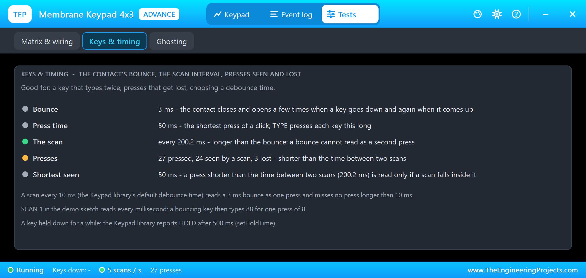
Only two of five presses reached the sketch. A 50 ms press is read only if one of the scans, 200 ms apart, happens to fall inside it; the other three slipped between two scans. The model counts them - 3 lost - and logs each one. A scan every 10 - 20 ms catches every human press: even a quick tap lasts more than that.
The Event Log
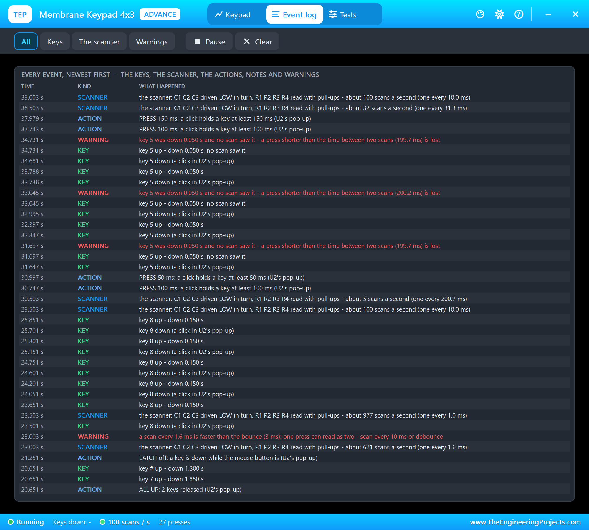
The Event log lists everything that happened, newest first: each key down and up with its source, the scanner each time it changes (lines and rate), the actions and the warnings - the lost presses, a scan faster than the bounce, the ghost key. Filter it, pause it, or clear it.
The Keypad and the STATUS Panel with the Mouse
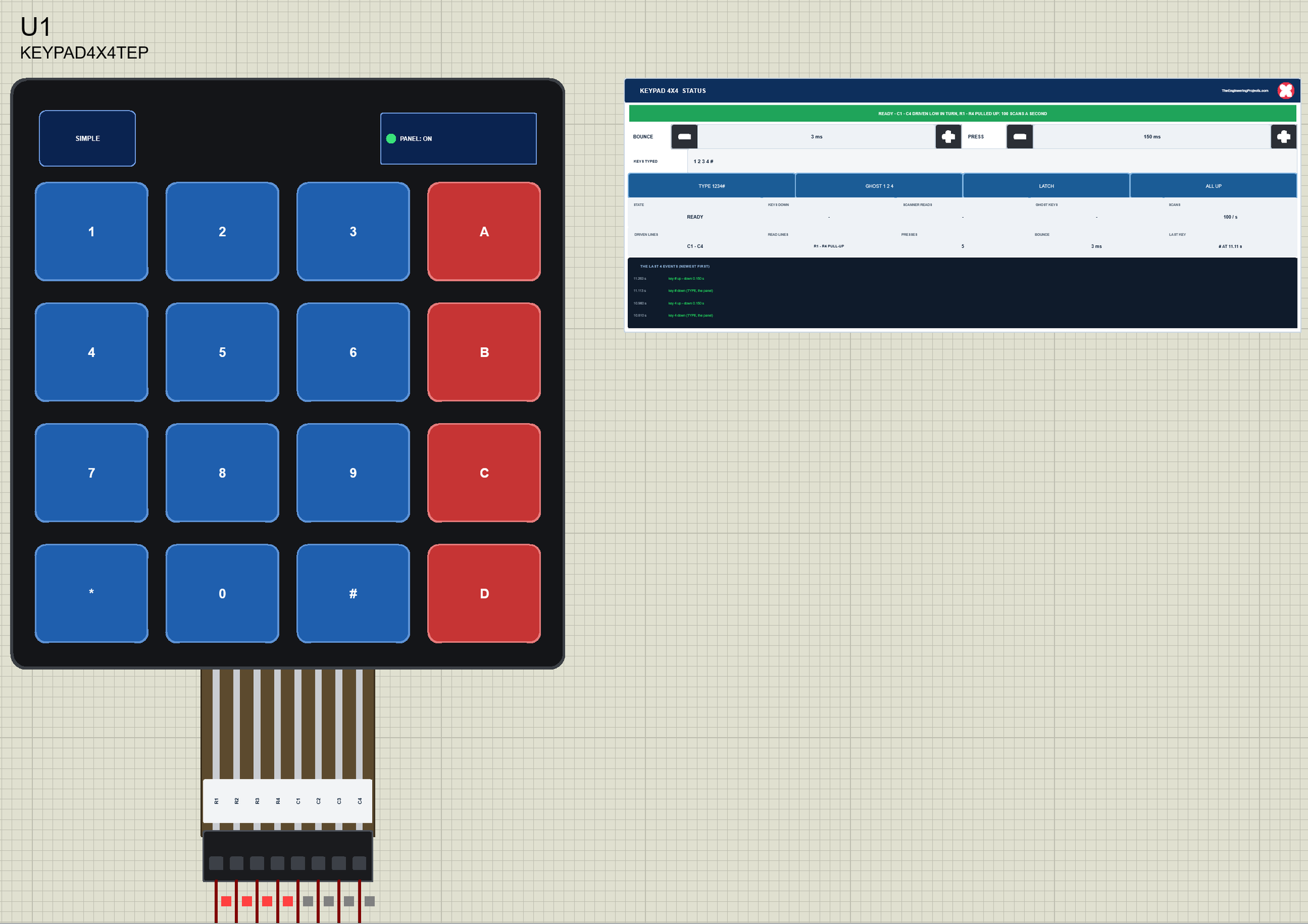
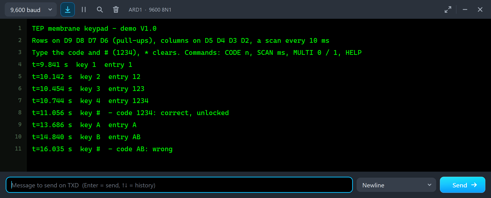
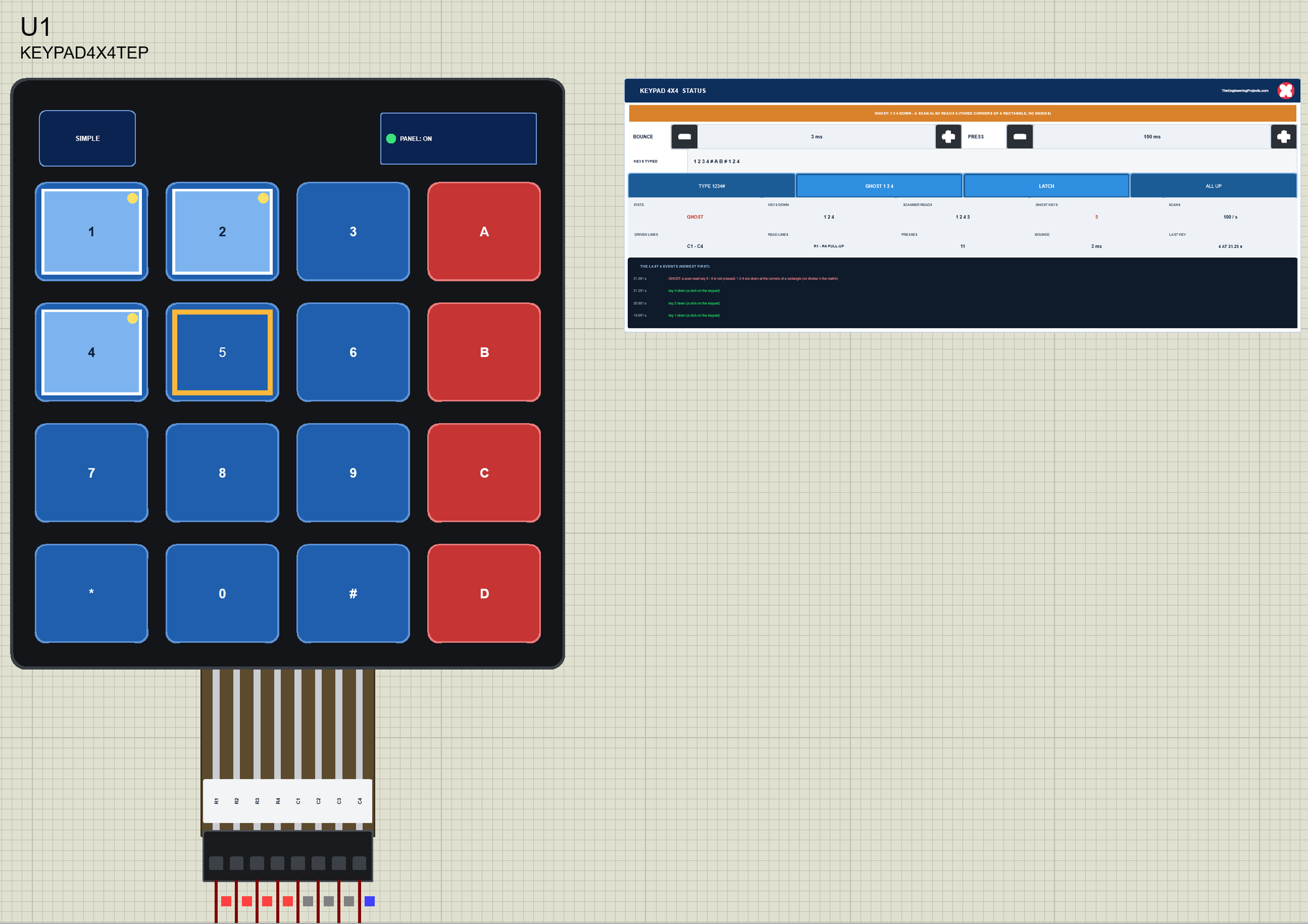
Back to node 1, the Simple 4x4 keypad. We clicked its panel and its keys with the mouse while the simulation ran. First TYPE 1234# on the panel, then A, B and # on the keypad:
t=9.841 s  key 1  entry 1
t=10.142 s  key 2  entry 12
t=10.454 s  key 3  entry 123
t=10.744 s  key 4  entry 1234
t=11.056 s  key #  - code 1234: correct, unlocked
t=13.686 s  key A  entry A
t=14.840 s  key B  entry AB
t=16.035 s  key #  - code AB: wrong
The letters work like the digits: AB is a valid entry, just not the code. Then LATCH on the panel, MULTI 1 in the monitor, and three clicks on the keypad - 1, 2 and 4:
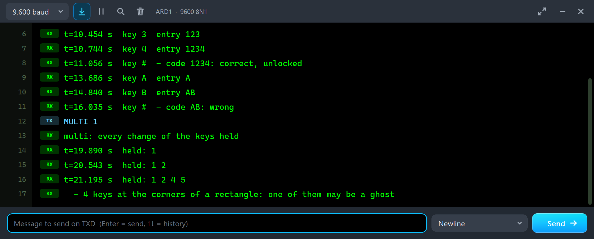
MULTI 1
multi: every change of the keys held
t=19.890 s  held: 1
t=20.543 s  held: 1 2
t=21.195 s  held: 1 2 4 5
  - 4 keys at the corners of a rectangle: one of them may be a ghost
Each click adds a key, and the third adds two: held: 1 2 4 5. On the keypad key 5 gets its amber ring while only 1, 2 and 4 carry the dots of LATCH. Finally ALL UP and LATCH off, and the red X and the PANEL button closed and reopened the STATUS panel.
The Simulation Log
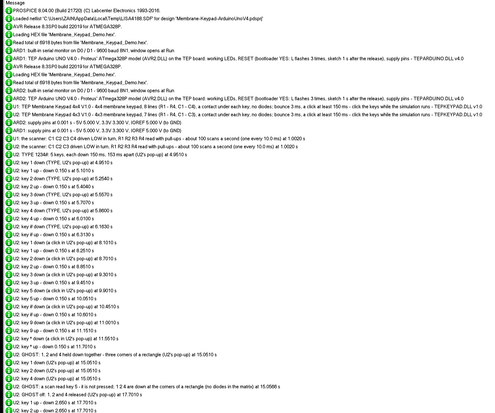
The keypads also write to the simulation log of Proteus, with the exact simulation time. These lines show the start of node 2:
U1: TEP Membrane Keypad 4x4 V1.0 - 4x4 membrane keypad, 8 lines (R1 - R4, C1 - C4), a contact under each key, no diodes; bounce 3 ms, a click at least 150 ms - click the keys while the simulation runs - TEPKEYPAD.DLL v1.0
U2: TEP Membrane Keypad 4x3 V1.0 - 4x3 membrane keypad, 7 lines (R1 - R4, C1 - C3), a contact under each key, no diodes; bounce 3 ms, a click at least 150 ms - click the keys while the simulation runs - TEPKEYPAD.DLL v1.0
U1: the scanner: C1 C2 C3 C4 driven LOW in turn, R1 R2 R3 R4 read with pull-ups - about 100 scans a second (one every 10.0 ms) at 1.0020 s
U2: the scanner: C1 C2 C3 driven LOW in turn, R1 R2 R3 R4 read with pull-ups - about 100 scans a second (one every 10.0 ms) at 1.0020 s
U2: TYPE 1234#: 5 keys, each down 150 ms, 153 ms apart (U2's pop-up) at 4.9510 s
U2: key 1 down (TYPE, U2's pop-up) at 4.9510 s
U2: key 1 up - down 0.150 s at 5.1010 s
U2: key 2 down (TYPE, U2's pop-up) at 5.2540 s
U2: key 2 up - down 0.150 s at 5.4040 s
Each keypad reports itself at the start; from the second half-second on it reports the scanner it found - C1 - C4 (C1 - C3) driven LOW in turn, R1 - R4 read with pull-ups, about 100 scans a second - and then every key, its source and how long it was down.
How the Model Works
The membrane keypad is a digital model. Its pins are bidirectional. Each time a line changes - or a contact, at the exact moments of a press, a release and the bounce - the model reads every line as the pins see it. Lines the circuit drives LOW (strong LOW the model does not drive itself) are its starting points; the model follows the closed contacts from them and drives every line they reach LOW too, 10 ns later. All other lines float. That is all a matrix of contacts does, so the ghost keys and the bounce come out by themselves, and the model knows which scan read which key. From the lines it also learns the scanner: a line that goes LOW in turn is driven, a line that stays weakly HIGH is pulled up.
Troubleshooting
- No key works: the sketch is not scanning, or the pins in the sketch are not the wired ones - Matrix & wiring shows what is driven and what is read.
- The wrong keys come out: rows and columns are swapped in the sketch, or your keypad has another pin order.
- A key types twice: the scan is faster than the bounce - scan every 10 ms or more.
- A short press gets lost: it was shorter than the time between two scans.
- A key reads as pressed without being pressed: a ghost - three keys at the corners of a rectangle.
- Keys that come and go: the rows float - pinMode(row, INPUT_PULLUP).
- No part or no monitor: TEPKEYPAD.DLL or TEPARDUINO.DLL is missing from MODELS and the project folder; a closed monitor opens again with a click on the UNO's USB port.
Things to Know Before Using a Real Membrane Keypad
- Pull-ups: use INPUT_PULLUP on the rows; no external resistors are needed.
- Idle columns: keep the columns that are not being scanned as INPUT, as the Keypad library does - with two keys in one row, an output LOW and an output HIGH would short through them.
- Pin order: check a 4x3 keypad with a meter before you wire it.
- The ribbon: it cracks if it is folded sharply; bend it in a loop.
- Mounting: the back is self-adhesive - peel the backing only when the keypad's place is final.
Limitations of the Simulation
- Not modelled: the contact resistance (small against the pull-ups), the ribbon's capacitance, keys pressed so lightly that they only half close, wear.
- The model's own choices: the bounce (four edges at random places in the first and last BOUNCE ms of a press), the 10 ns delay, PRESS, the TYPE timing and the GHOST keys.
- The badge, the panel button, the pin label and the panels are TEP additions.
- The model is our own implementation of a key matrix. This library is not made or endorsed by the keypads' makers or by Labcenter.
- Licences: the demo sketch uses no library; the HEX file contains the Arduino AVR core 1.8.6 with LGPL-licensed code - the source link is in the README.
- Tested in Proteus 8.5 in October 2026 (the demo as shipped on two Arduino UNO V4.0 boards with their built-in monitors: TYPE 1234#, a wrong code, *, GHOST with MULTI 1, LATCH, SCAN 1 and SCAN 200 with the three tools on the Advance 4x3 keypad; TYPE 1234#, A, B and #, LATCH with 1, 2 and 4, the red X and PANEL with the mouse on the Simple 4x4 one; 40.8 s of simulation took 140 s, about 0.29 x real time with the pop-up and both monitors open; the second run, node 1 with the mouse, 37.1 s in 90 s). Proteus 7 is not supported.
So, that was all about the Membrane Keypad Library for Proteus V1.0. I hope the scan, the ghost keys and the bounce are clear now, and that your code lock, menu or calculator works from the first run. If you use the Membrane Keypad Library for Proteus in a project, please share it in the comments or in our forum, and if you have any questions, ask in the comments and I will help you out. Till the next tutorial, take care and have fun!
Comments
0