


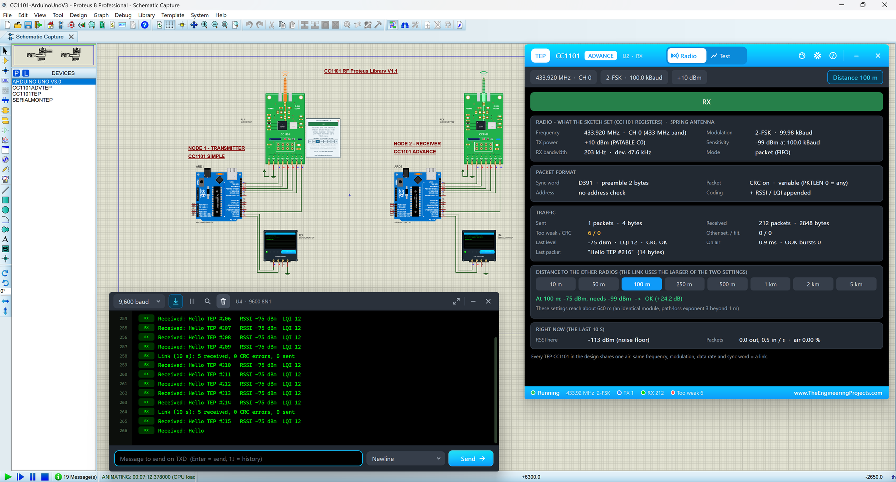
CC1101 Library for Proteus V1.1 (433 MHz RF + Arduino)


Hello friends, I hope you all are doing great. Today, I am going to share the new CC1101 Library for Proteus V1.1. The CC1101 is Texas Instruments' small sub-1 GHz radio, and the green 433 MHz board with the copper spring antenna is a favourite for wireless sensors and 433 MHz remote controls. With this CC1101 Library for Proteus, two modules in one design talk over a simulated 433 MHz air, and your Arduino drives them over SPI with the same SmartRC-CC1101 library you use on real hardware.
CC1101 Library for Proteus
Latest version: V1.1 (September 2026, this tutorial)
Helping Tools
- Serial Monitor Advance: a serial terminal window for the UART of your board
- Serial Monitor Expert: the serial monitor with extra debugging tools
- LCD Library for Proteus V3.0: 16x2, 20x4 and I2C LCDs to show your readings
Version 1.1 replaces the first version of this post. You now get two devices: CC1101 Simple, with its control panel on the schematic, and CC1101 Advance, with a pop-up window and five measured RF test tools. The new CC1101 Arduino Proteus demo has two Arduino UNOs that send packets, PING each other and even sniff and replay a 433 MHz remote code, shown in the compact Simple interface of our TEP Serial Monitor. Have you read version 1.0? Then jump to "What's New" below.
NOTICE: This library is very special to our team. Our CC1101 model has the chip's registers, strobes, FIFOs and packet engine, works out the signal level at every distance and even relays 433 MHz remote-control codes. It took our team a lot of hard work, many test runs and many design changes. Your feedback is the fuel that keeps us going, so please tell us what you think in the comments below or in the CC1101 Library board of our forum. And if our free libraries help you, you can buy us a coffee. So, let's get started with the CC1101 Library for Proteus:
What is the CC1101 Sub-1 GHz RF Module?
The CC1101 is a radio transceiver (it sends and receives) made by Texas Instruments for the licence-free bands below 1 GHz: 315, 433, 868 and 915 MHz. A lower frequency loses less signal on its way than 2.4 GHz, so sub-1 GHz radios are popular for remote controls, garage doors, alarm sensors, weather stations and home automation. The Arduino talks to the chip over SPI, a 4-wire bus (clock, data in, data out and chip select), and two extra pins, GDO0 and GDO2, signal what the radio is doing.
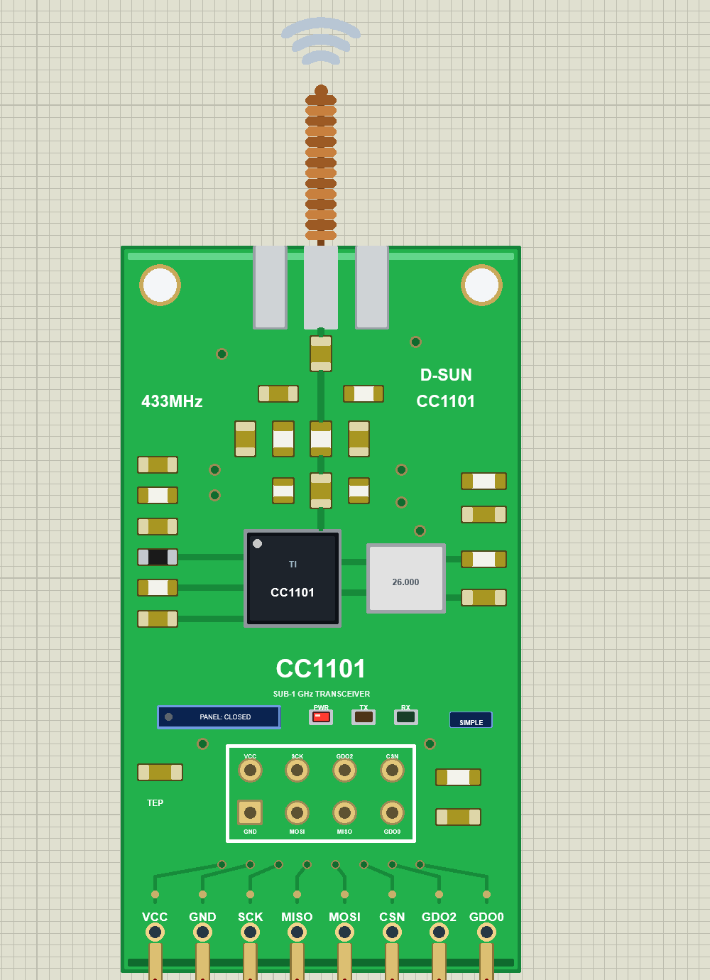
The most common board is the small green D-SUN 433 MHz module: a copper spring antenna at the top, the CC1101 with its 26 MHz crystal in the middle and a 2 x 4 header at the bottom. Want to see a simpler 433 MHz remote module at work first? Read our 433 MHz remote control RF module tutorial.
The CC1101 at a Glance
| Feature | Value |
|---|---|
| Frequency bands | 300 - 348, 387 - 464 and 779 - 928 MHz; modules are sold for 315, 433, 868 or 915 MHz |
| Modulation | 2-FSK, GFSK, 4-FSK, MSK and ASK / OOK |
| Data rate | 0.6 to 600 kBaud (our demo sketches accept 0.6 - 500) |
| TX power | Up to +12 dBm; the demo uses +10 dBm, SmartRC's default at 433 MHz |
| Sensitivity (our model, 2-FSK) | -112 dBm at 1.2 kBaud, -104 at 38.4, -99 at 100, -95 at 250 and -86 dBm at 500 kBaud; ASK / OOK 4 dB worse |
| Buffers | A 64-byte TX FIFO and a 64-byte RX FIFO |
| Packet engine | Preamble, sync word, length byte, address check, CRC; RSSI and LQI appended |
| Supply | 1.8 - 3.6 V; the pins are NOT 5 V tolerant |
| Interface | SPI plus the GDO0 and GDO2 outputs; a 26 MHz crystal |
CC1101, nRF24L01, HC-12, LoRa or RFM69: Which Library Do You Need?
| Your module | What it does | Our library |
|---|---|---|
| CC1101 (green D-SUN board, spring antenna) | 315 / 433 / 868 / 915 MHz, SPI, packets and OOK remote codes | This article |
| nRF24L01 (PCB antenna) | 2.4 GHz, SPI, short range | nRF24L01 Library for Proteus |
| nRF24L01+PA+LNA (SMA antenna) | 2.4 GHz with a power amplifier and an LNA, longer range | nRF24L01+PA+LNA Library for Proteus |
| HC-12 | 433 MHz wireless serial module (UART) | HC-12 Library for Proteus |
| SX1278 / Ra-02 | 433 MHz LoRa, long range at low data rates, SPI | SX1278 LoRa Library for Proteus |
| RFM69HCW | 315 / 433 / 868 / 915 MHz FSK with ACKs, SPI | RFM69HCW Library for Proteus |
All of them are compared in our RF Module Libraries for Proteus roundup.
Radio Terms You Will See in This Article
| Term | Meaning |
|---|---|
| Sub-1 GHz | The licence-free bands below 1 GHz (315, 433, 868, 915 MHz); which ones you may use depends on your country |
| 2-FSK, GFSK | Frequency shift keying: a 1 is sent a little above the carrier, a 0 a little below it (the deviation, 47.6 kHz in the demo); GFSK smooths the steps |
| OOK (ASK) | On-off keying: the carrier is simply switched on and off, like a 433 MHz remote control |
| kBaud | Thousands of symbols per second on the air; with 2-FSK, one symbol is one bit |
| dBm | Power compared to 1 mW: 0 dBm = 1 mW, +10 dBm = 10 mW, and every 10 dB is a factor of 10 |
| Sensitivity | The weakest signal the receiver can still decode at its data rate |
| RSSI | Received Signal Strength Indicator: the level of the last packet in dBm |
| LQI | Link Quality Indicator: how cleanly the packet was received; on the CC1101 a LOWER number is better |
| Preamble, sync word | Alternating bits that wake the receiver, then a 2-byte pattern (D391 in the demo) that marks the start of a packet |
| CRC | A check value at the end of the packet that reveals damaged packets |
| Packet mode, async mode | The chip builds and checks whole packets in its FIFOs, or it passes raw bits on the GDO0 pin (asynchronous serial mode) |
| PATABLE | The chip's power table: the byte that sets the TX power (C0 = +10 dBm at 433 MHz) |
| Duty cycle | The share of time a transmitter is on the air; Europe limits it to 10 % or 1 % in some bands |
How Two CC1101 Radios Talk: Packets, FSK and OOK
In the demo, the radios use packet mode: the chip does the radio work, and the sketch only hands it a message and reads the result. One packet, step by step:
- SmartRC's
SendData()writes the length byte and the message into the 64-byte TX FIFO and starts the transmitter. - The chip calibrates for 809 + 90 us, then sends 2 bytes of preamble, the sync word D391, the length byte, the data and a 2-byte CRC. At 100 kBaud, a byte takes 80 us.
- GDO0 goes HIGH when the sync word is out and LOW at the end of the packet.
- A receiver on the same frequency, modulation, data rate and sync word stores the bytes, checks the CRC and appends the RSSI and the LQI.
- Its GDO0 pulses the same way, and the sketch reads the packet with
ReceiveData().
Notice what is missing: an ACK. Unlike the nRF24L01, a CC1101 never answers "got it", so the transmitter cannot know whether anybody heard it. The PING and PONG of the v1.1 demo show how to add a reply.
2-FSK or OOK?
With 2-FSK, the carrier never stops: it moves 47.6 kHz up for a 1 and down for a 0. With OOK, the carrier is simply on for a 1 and off for a 0, as in cheap 433 MHz remote controls. OOK is simpler, but in our model it needs a signal 4 dB stronger. 2-FSK and GFSK hear each other; other modulations must match exactly.
kBaud and Range: Why 1.2 kBaud Reaches Further
The level at the receiver is the TX power minus the path loss, the signal lost on the way. While it stays above the receiver's sensitivity, the link works. Our model uses free-space loss up to 1 m and a path-loss exponent of 3 beyond it: at 433 MHz, 85 dB at 100 m and 115 dB at 1 km (6 dB more at 868 MHz). With the demo's +10 dBm:
- 100 m: +10 - 85 = -75 dBm. 100 kBaud needs -99 dBm, so the link is OK with a margin of +24.2 dB.
- 1 km: +10 - 115 = -105 dBm: 6 dB too weak at 100 kBaud, but OK at 1.2 kBaud, which needs only -112 dBm.
Why? A slower bit carries more energy, and the receiver can use a narrower filter that lets in less noise. The price is time: a 32-byte packet is on the air for 3.12 ms at 100 kBaud, but for 260 ms at 1.2 kBaud.
RSSI and LQI
Every received packet carries its RSSI, the level in dBm, and its LQI, how cleanly it was received. On the CC1101 a lower LQI is better: 12 at 100 m, 46 at 1 km with 1.2 kBaud. In our model, a signal less than 1.5 dB above the sensitivity arrives with a CRC error.
Sync Word, CRC and Why Both Nodes Must Match
A receiver accepts only packets that start with its own sync word (D391, the default; setSyncMode(2) makes all 16 bits count), and the CRC reveals damaged ones. So two CC1101 radios form a link only when they agree on the frequency (within the receiver's 203 kHz bandwidth), the modulation, the data rate (within 10 %), the sync word and the packet format. That is why the FREQ, RATE and MOD commands of the demo must be typed on both monitors.
Packet Mode and Asynchronous Mode: 433 MHz Remote Codes
In asynchronous serial mode (SmartRC's setCCMode(0)), there is no FIFO and no packet: the level of GDO0 keys the carrier, and a receiver puts what it hears on its own GDO0. This is how a CC1101 talks to 433 MHz remote controls. Careful: SmartRC starts in this mode after Init(), so a packet sketch must call setCCMode(1).
Most remotes use protocol 1 of the popular rc-switch Arduino library, built on a short pulse T of 350 us: a 0 is 1 T high and 3 T low (1 : 3), a 1 is 3 T high and 1 T low (3 : 1), and a sync of 1 T high and 31 T low ends every frame. Our demo sends the 24-bit code 5393 (binary 000000000001010100010001, 0x1511) four times with a few lines of its own, so you don't need the rc-switch library.
What's New in CC1101 Library for Proteus V1.1
If you used version 1.0, here is what has changed:
- Two devices in
TEPCC1101.LIB: CC1101 Simple (CC1101TEP, the v1.0 device, so old designs keep working) and CC1101 Advance (CC1101ADVTEP) with a pop-up window. - A redrawn board: a tall green board like the real D-SUN module instead of v1.0's wide blue one. The 8 Proteus pins stay where they were, so v1.0 wiring fits.
- A live antenna and three LEDs: spring, pad and RF trace glow orange while sending and green while receiving. PWR, TX and RX are a TEP addition: the real module has no LEDs.
- Close and reopen: a red X and a PANEL button on the Simple, OPEN PANEL on the Advance.
- Five measured test tools (Advance): Link test, Throughput, Scan, Registers and OOK.
- Model: the radio records what the tools show, and an unpowered CC1101 can no longer stall the simulation. The DISTANCE buttons and the link budget are unchanged.
- A two-UNO demo with the TEP Serial Monitor instead of Virtual Terminals. The sketches keep every v1.0 output line and add commands (SEND, PING, STATUS, FREQ, RATE, MOD, HELP; AUTO and OOK on node 1, SNIFF on node 2) and a link line every 10 s.
- Lighter package: about 1.5 MB, without the C++ source code (v1.0: about 7.4 MB).
A v1.0 design keeps its old symbol: new model and DISTANCE buttons, but no new board, LEDs or red X. Here its panel still shows the chip's reset values:
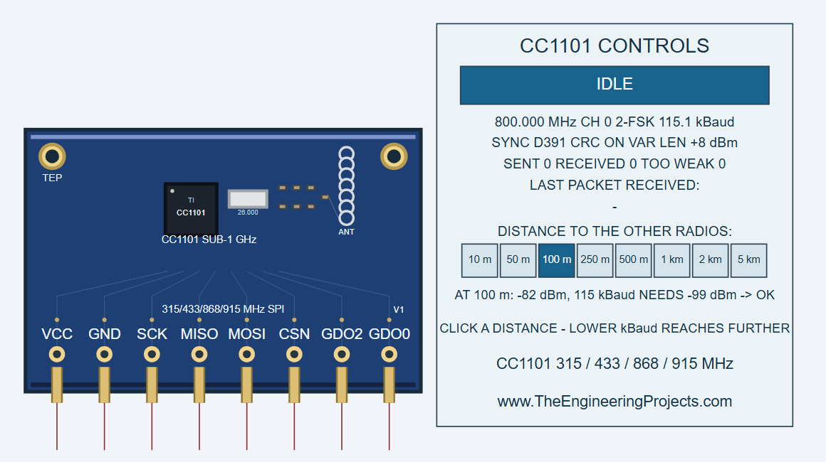
CC1101 Library for Proteus: Simple vs Advance
Both devices run the same model; only the panel differs:
| Feature | Simple | Advance |
|---|---|---|
| Full CC1101 model (SPI, registers, strobes, FIFOs, packet engine, async mode, GDO0 / GDO2, timing) | ✔ | ✔ |
| Green D-SUN board, glowing spring antenna and PWR / TX / RX LEDs | ✔ | ✔ |
| DISTANCE buttons 10 m - 5 km and the link-budget verdict | ✔ | ✔ |
| Control panel on the schematic (state, settings, counters, last packet) | ✔ | ✘ |
| Pop-up window you can move, resize and minimise | ✘ | ✔ |
| Radio page: what the sketch set, packet format, traffic, reach, right now | ✘ | ✔ |
| Link test, Throughput, Scan, Registers and OOK | ✘ | ✔ |
| TEP Dark / Light theme, text size, Help page with Copy diagnostics | ✘ | ✔ |
| Same device name as v1.0 (old designs keep working) | ✔ | ✘ |
Choose Simple to keep the radio's state beside your circuit, and Advance for hard numbers about your link. The demo has one of each, and the two talk to each other.
Download CC1101 Library for Proteus
Click the button below to download CC1101-RF-Library-for-Proteus-v1.1.zip (about 1.5 MB, without the C++ source code):
CC1101 Library for Proteus V1.1- README.txt: a detailed guide to the files, the wiring, the model, the test tools and real hardware.
- Proteus Library Files:
TEPCC1101.LIB(both devices),TEPSERIALMON.LIBand our Arduino UNO libraryArduinoV3TEP.LIB/ArduinoV3TEP.IDX. - Proteus Model Files:
TEPCC1101.DLLandTEPSERIALMON.DLL. - Proteus Simulation:
CC1101-ArduinoUnoV3.pdsprj,CC1101_Transmitter.hex,CC1101_Receiver.hexand copies of both DLLs. - Arduino Code:
CC1101_Transmitter.ino,CC1101_Receiver.inoand the SmartRC-CC1101-Driver-Lib 3.0.2 (LSatan, based on the ELECHOUSE CC1101 library by Wilson Shen), unmodified, under the MIT License with its LICENSE file (its examples folder is left out).
No Proteus yet? Read How to Download and Install Proteus 7 and 8. New to libraries? Follow How to Install a New Library in Proteus.
How to Install CC1101 Library for Proteus
- Close Proteus and extract the whole zip file.
- Copy the four files from Proteus Library Files into the LIBRARY folder, usually
C:\Program Files (x86)\Labcenter Electronics\Proteus 8 Professional\LIBRARY(on some PCsC:\ProgramData\Labcenter Electronics\Proteus 8 Professional\LIBRARY). - Copy
TEPCC1101.DLLandTEPSERIALMON.DLLinto the MODELS folder. - Start Proteus, press P and search for CC1101. You get the Simple and the Advance device (category Peripherals > Wireless).
Updating from v1.0? Replace TEPCC1101.LIB and TEPCC1101.DLL, and delete TEPCC1101.IDX if there is one in LIBRARY. A v1.0 design keeps its v1.0 symbol and runs with the new model; re-pick the part to get the v1.1 board. Tested in Proteus 8.5; Proteus 7 is not supported.
The CC1101 Board in Proteus
We designed the module as a clean TEP board shaped like the green D-SUN 433 MHz module: the copper spring antenna on the top edge, an RF trace with its matching network down to the CC1101 and its 26.000 MHz crystal, then the board button, three LEDs, a SIMPLE or ADVANCE badge and the 2 x 4 header. Here is U1, the Simple device, while it sends:
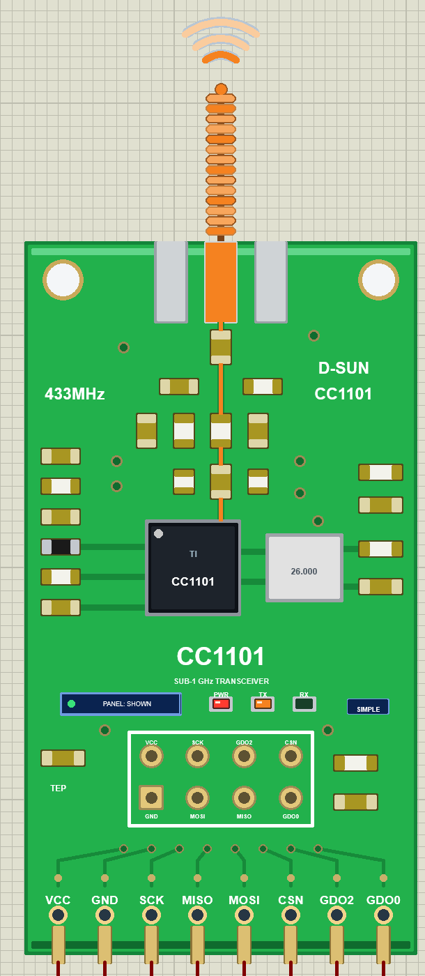
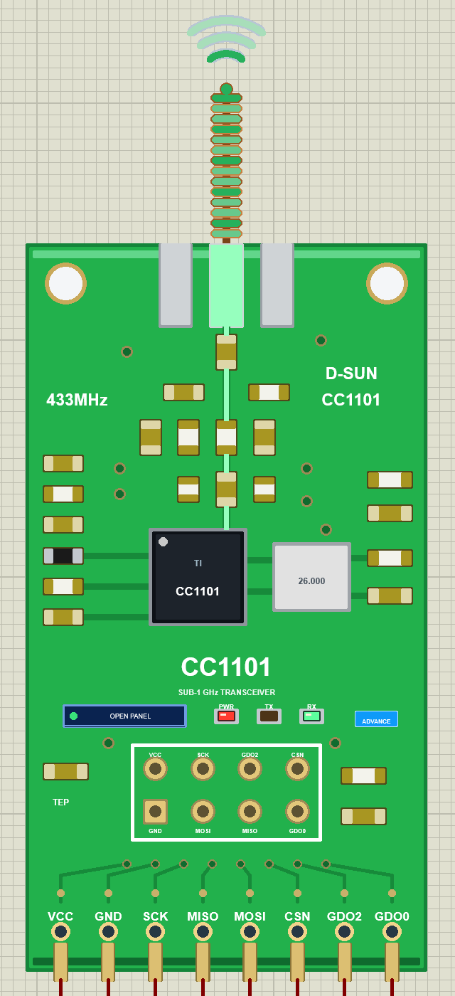
The spring, the antenna pad and the RF trace glow orange, and the waves ripple out. PWR and TX are lit, but RX stays dark: there is no ACK to receive. On U2, the Advance device, the same parts glow green when a packet arrives:
Pinout
The eight Proteus pins keep the v1.0 order. The real D-SUN header, drawn on our board, reads VCC SCK GDO2 CSN / GND MOSI MISO GDO0, and other modules, such as the Ebyte E07-M1101D, use another order, so always wire by the names:
| Pin | Function | Demo connection |
|---|---|---|
| VCC | Power (3.3 V on a real module) | Supply terminal |
| GND | Ground | GND |
| SCK | SPI clock from the Arduino | Arduino D13 |
| MISO | SPI data from the radio | Arduino D12 |
| MOSI | SPI data to the radio | Arduino D11 |
| CSN | SPI chip select, active LOW | Arduino D10 |
| GDO2 | General output 2 (SmartRC sets it to the serial clock) | Arduino D9, not used by the sketches |
| GDO0 | General output 0: sync word / end of packet in packet mode, the data pin in async mode | Arduino D2 |
Spring, LEDs and Waves
| Indicator | What it shows |
|---|---|
| PWR LED (red) | Lit while VCC and GND are connected |
| TX LED (orange) | Blinks for every packet or OOK burst sent |
| RX LED (green) | Blinks for every packet received |
| Spring, antenna pad, RF trace | Copper and silver at rest, orange while sending, green while receiving (the bright turn travels up or down the spring) |
| Waves above the spring | Ripple out while sending, in while receiving |
| PANEL / OPEN PANEL, SIMPLE / ADVANCE | The panel button and the device badge |
Each blink is held 0.3 - 0.4 s, so you see it. There are no properties to edit: your sketch sets the radio over SPI, as on the real chip, and you choose the DISTANCE on the panel (100 m at every Run).
CC1101 Simple: The Control Panel on the Sheet
Beside the Simple board, the CC1101 CONTROLS panel shows what the radio is doing, without one debug line in your sketch. Here is the panel of U1 at the default 100 m:
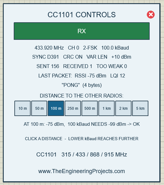
| Part | What it shows |
|---|---|
| Header, red X | CC1101 CONTROLS; the X closes the panel |
| State bar | For example RX (green), TX - SENDING (orange), IDLE, SLEEP or NO POWER - CHECK VCC / GND (red); (ASYNC) is added in asynchronous mode |
| Settings line 1 | 433.920 MHz CH 0 2-FSK 100.0 kBaud: what the sketch wrote |
| Settings line 2 | SYNC D391 CRC ON VAR LEN +10 dBm (VAR LEN: a length byte in every packet) |
| Counters | SENT, RECEIVED, TOO WEAK (CRC ERR appears after the first CRC error) |
| LAST PACKET | RSSI and LQI of the last packet received, then its text and length |
| DISTANCE TO THE OTHER RADIOS | 10 m, 50 m, 100 m, 250 m, 500 m, 1 km, 2 km, 5 km |
| Verdict | AT 100 m: -75 dBm, 100 kBaud NEEDS -99 dBm -> OK |
| Hint | CLICK A DISTANCE - LOWER kBaud REACHES FURTHER |
Why the Transmitter Says RX
U1 is the transmitter, yet its bar says RX. That is correct: the v1.1 transmitter listens between its packets, so node 2 can PING it or SEND it a message (its last packet is the PONG from my PING test). A Hello packet takes only a few milliseconds every 2 s, so the panel rarely catches TX - SENDING, but the TX LED and the orange spring show every one.
DISTANCE: 100 m Works, 1 km Is TOO WEAK
Now click 1 km on the panel of U1. The verdict turns to -105 dBm, TOO WEAK, because 100 kBaud needs -99 dBm:
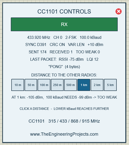
From now on, U4 stays silent while U3 keeps printing "Sent: Hello TEP #n": without an ACK, the transmitter never notices. U2 counts the weak packets on its Radio page. The link uses the larger of the two radios' DISTANCE settings, so bringing them back needs a short distance on both.
Lower kBaud Reaches Further: RATE 1.2 at 1 km
The hint at the bottom of the panel says it: a lower kBaud reaches further. Leave the distance at 1 km and type RATE 1.2 in the send box of BOTH Serial Monitors (one node alone would break the link). The panel of U1 now shows 1.2 kBaud, and the verdict says OK again:
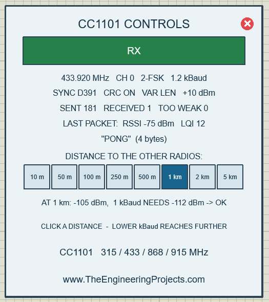
On U4, the packets come back:
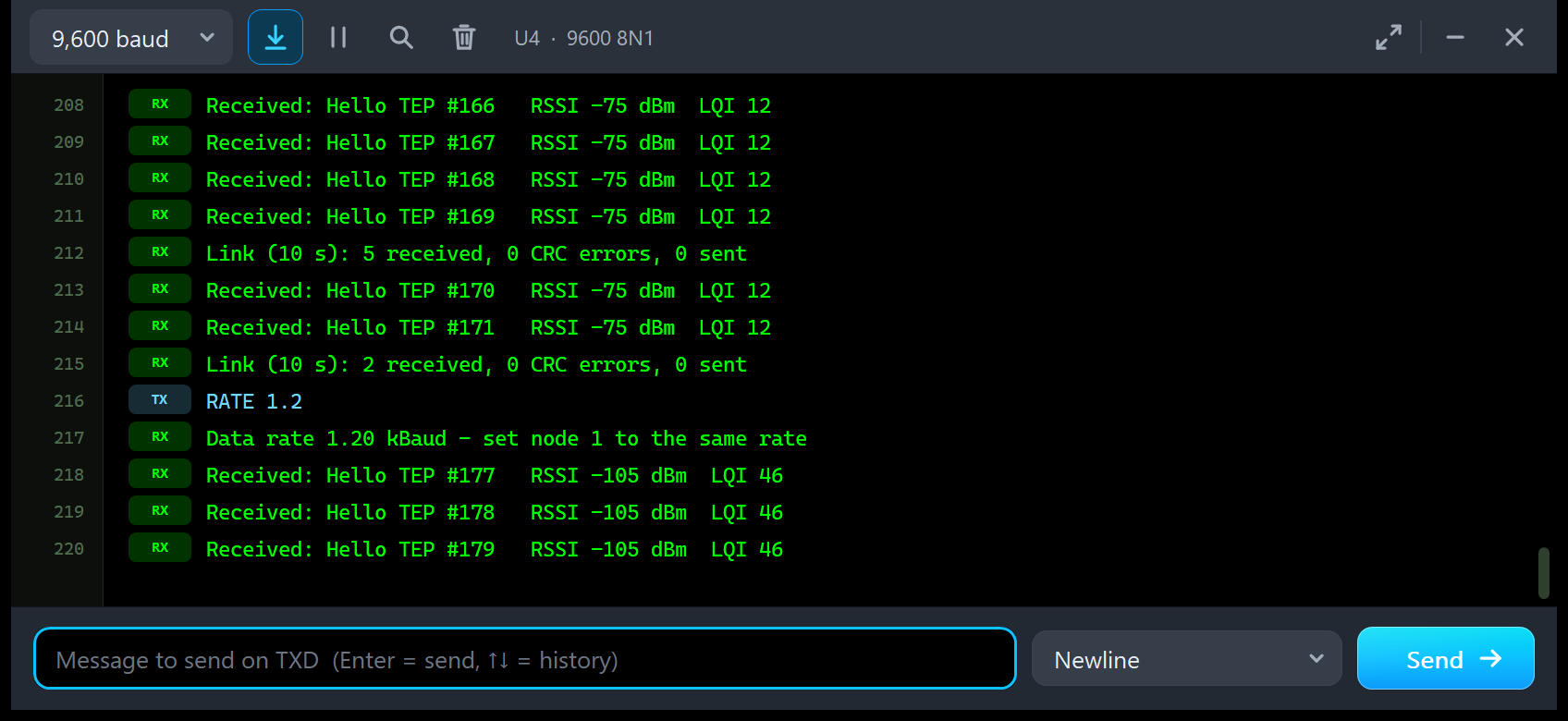
Received: Hello TEP #171   RSSI -75 dBm  LQI 12
Link (10 s): 2 received, 0 CRC errors, 0 sent
RATE 1.2
Data rate 1.20 kBaud - set node 1 to the same rate
Received: Hello TEP #177   RSSI -105 dBm  LQI 46
Received: Hello TEP #178   RSSI -105 dBm  LQI 46
Received: Hello TEP #179   RSSI -105 dBm  LQI 46
Packets #172 to #176 were sent while the radios stood 1 km apart, before both nodes ran at 1.2 kBaud, and never arrived. From #177 on, every packet arrives at -105 dBm, with LQI 46 instead of 12: the margin is now 7 dB instead of 24. To go back, click 100 m and type RATE 100 on both monitors.
Closing the Panel
Need room on the sheet? Click the red X. The board button says PANEL: CLOSED with a grey dot, while the radio and the sketch keep running. Click PANEL to bring it back.
CC1101 Advance: The Pop-Up Window
The Advance device keeps only the board on the schematic. At Run, the "TEP CC1101 Advance" pop-up opens with the look of our Serial Monitor and no Windows title bar: move it by its header, resize or minimise it, and reopen it with OPEN PANEL. The header shows the state (U2 · RX) and the Radio and Test tabs; the blue status bar counts TX and RX.
The Radio Page
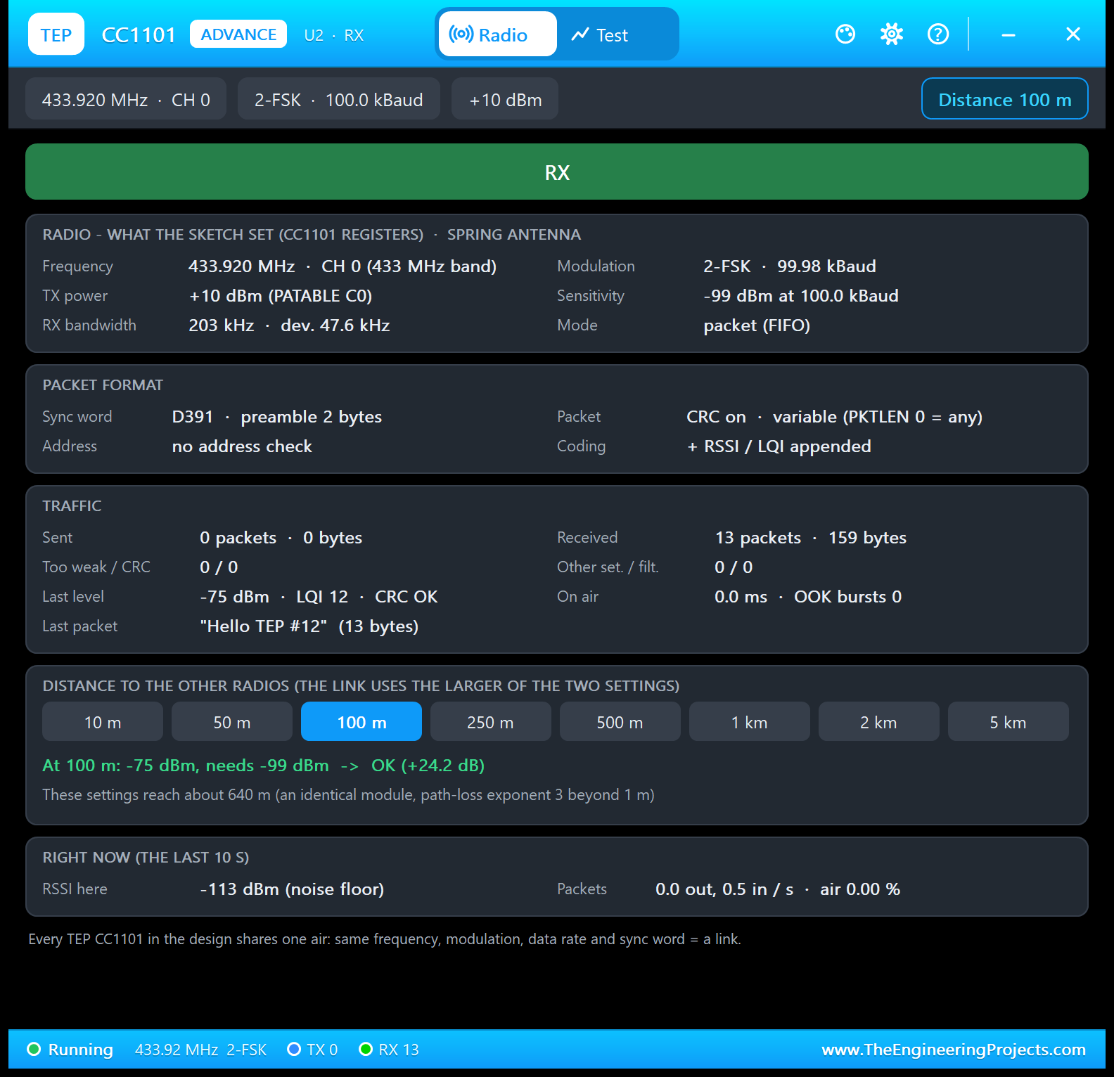
- RADIO: what the sketch set: 433.920 MHz, CH 0; +10 dBm (PATABLE C0); RX bandwidth 203 kHz, deviation 47.6 kHz; 2-FSK at 99.98 kBaud; sensitivity -99 dBm; packet (FIFO) mode.
- PACKET FORMAT: sync word D391, preamble 2 bytes, CRC on, variable length, no address check, RSSI / LQI appended.
- TRAFFIC: 13 packets (159 bytes) received, none too weak or damaged; the last, "Hello TEP #12", at -75 dBm, LQI 12, CRC OK.
- DISTANCE: "OK (+24.2 dB)" and my favourite line, "These settings reach about 640 m".
- RIGHT NOW: -113 dBm, the noise floor between packets, and 0.5 packets in per second.
The Test Page: Five Measured CC1101 Test Tools
Every number on the Test tab is measured on the running model, and each tool ends with a "Good for:" line.
1. Link Test: How Far Does Your Link Reach?
Choose 10, 20 or 50 packets and click Run test. The tool records the next real packets this radio sends or hears on its frequency, with the outcome, the level and the LQI. A CC1101 sends no ACK, so "received" means the other radio got it. The DISTANCE buttons sit on the tool, so you can move the radios mid-test. 10 packets at 100 m:
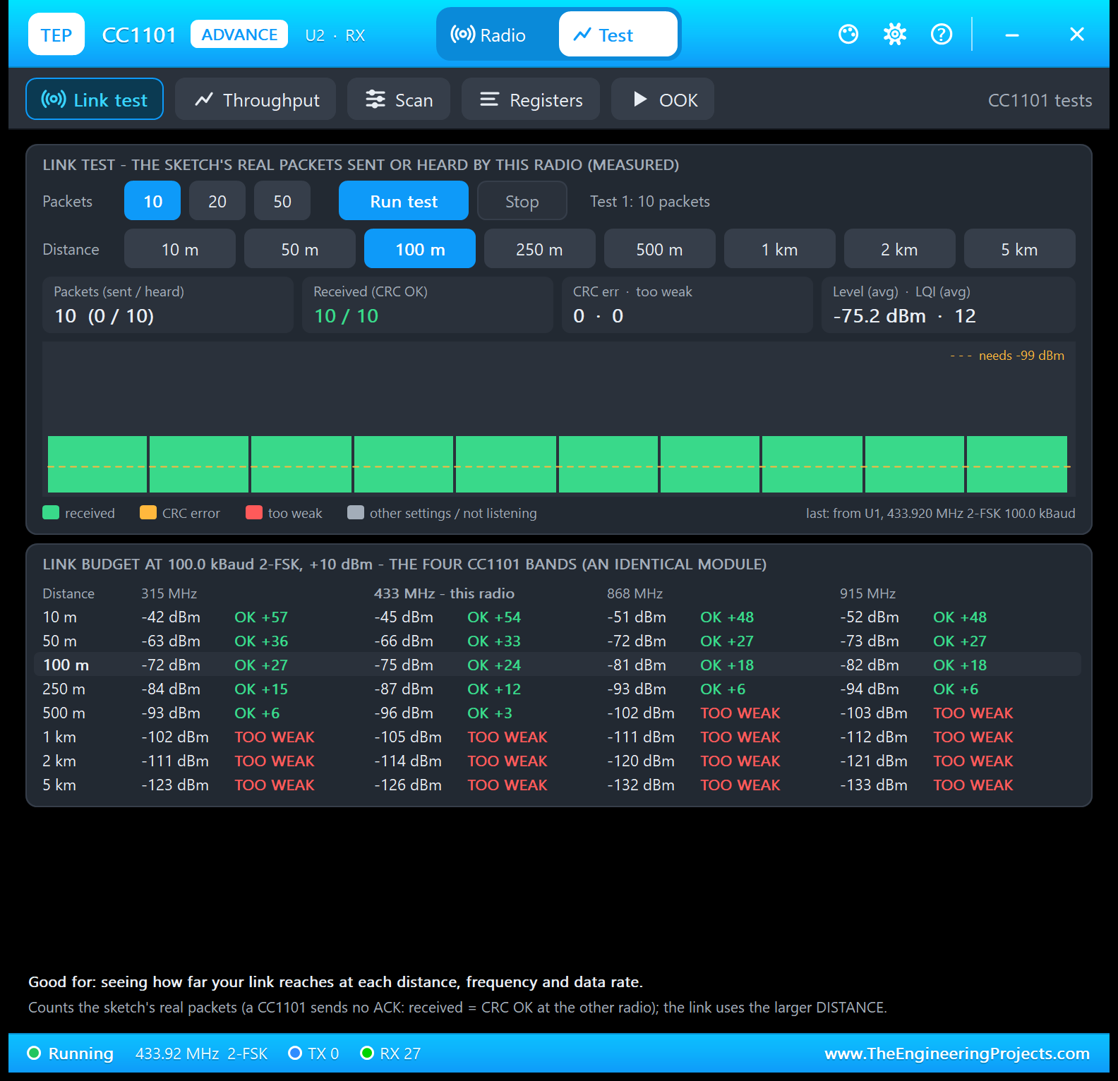
U2 heard 10 packets from U1, all with CRC OK, at -75.2 dBm and LQI 12 on average; every green bar stands above the dashed "needs -99 dBm" line. Click 1 km during a test, and the bars turn red: too weak at -105.2 dBm. Below, the tool shows the link budget in all four CC1101 bands:
| Distance | 315 MHz | 433 MHz (this radio) | 868 MHz | 915 MHz |
|---|---|---|---|---|
| 10 m | -42 dBm, OK +57 | -45 dBm, OK +54 | -51 dBm, OK +48 | -52 dBm, OK +48 |
| 50 m | -63 dBm, OK +36 | -66 dBm, OK +33 | -72 dBm, OK +27 | -73 dBm, OK +27 |
| 100 m | -72 dBm, OK +27 | -75 dBm, OK +24 | -81 dBm, OK +18 | -82 dBm, OK +18 |
| 250 m | -84 dBm, OK +15 | -87 dBm, OK +12 | -93 dBm, OK +6 | -94 dBm, OK +6 |
| 500 m | -93 dBm, OK +6 | -96 dBm, OK +3 | -102 dBm, TOO WEAK | -103 dBm, TOO WEAK |
| 1 km | -102 dBm, TOO WEAK | -105 dBm, TOO WEAK | -111 dBm, TOO WEAK | -112 dBm, TOO WEAK |
| 2 km | -111 dBm, TOO WEAK | -114 dBm, TOO WEAK | -120 dBm, TOO WEAK | -121 dBm, TOO WEAK |
| 5 km | -123 dBm, TOO WEAK | -126 dBm, TOO WEAK | -132 dBm, TOO WEAK | -133 dBm, TOO WEAK |
A higher frequency loses more on the way: at 500 m, 433 MHz is still OK with 3 dB to spare, while 868 and 915 MHz are too weak. Good for: seeing how far your link reaches.
2. Throughput: How Many Packets per Second?
This tool does not use your sketch. Two model radios in a private test air send 50 packets back to back at this radio's distance, frequency and power. You choose the data rate, the payload and the TX mode: SendData(), which calibrates before every packet like SmartRC, or FSTXON.
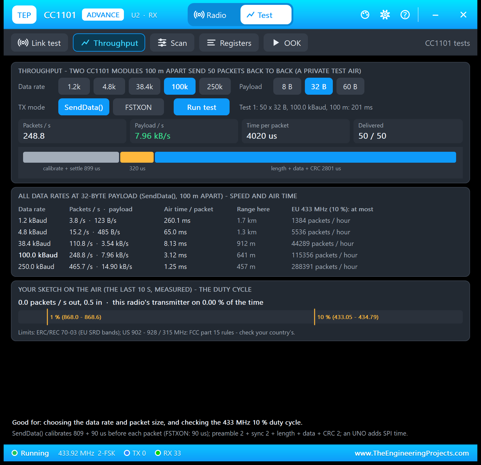
The 50 packets took 201 ms: 248.8 packets/s, 7.96 kB/s of payload. The bar splits the 4020 us per packet: 899 us to calibrate and settle, 320 us of preamble and sync word, and 2801 us for the length byte, the 32 data bytes and the CRC. FSTXON skips most of the calibration: 311.5 packets/s. A real UNO adds its SPI time. The second card compares all data rates:
| Data rate | Packets / s | Payload / s | Air time / packet | Range here | EU 433 MHz (10 %): at most |
|---|---|---|---|---|---|
| 1.2 kBaud | 3.8 | 123 B/s | 260.1 ms | 1.7 km | 1384 packets / hour |
| 4.8 kBaud | 15.2 | 485 B/s | 65.0 ms | 1.3 km | 5536 packets / hour |
| 38.4 kBaud | 110.8 | 3.54 kB/s | 8.13 ms | 912 m | 44289 packets / hour |
| 100.0 kBaud | 248.8 | 7.96 kB/s | 3.12 ms | 641 m | 115356 packets / hour |
| 250.0 kBaud | 465.7 | 14.90 kB/s | 1.25 ms | 457 m | 288391 packets / hour |
That is the whole trade-off: 1.2 kBaud reaches 1.7 km but carries 123 bytes per second, while 250 kBaud carries 14.9 kB/s but ends at 457 m.
And the last column? In Europe, a transmitter in the 433.05 - 434.79 MHz band may be on the air at most 10 % of the time (868.0 - 868.6 MHz: 1 %): 360 s per hour, or 1384 packets of 260.1 ms at 1.2 kBaud. The third card measures your own sketch against the 1 % and 10 % marks; U2 only listens, so it reads 0.00 %. Good for: choosing the data rate and packet size, and checking the duty cycle.
3. Scan: Which Frequencies Are Busy?
Choose 1, 5 or 10 s. The scan never changes the radio's registers; it lists every packet and OOK burst of the TEP CC1101 radios in your design by sender, frequency, data rate and modulation, in band views for 315, 433, 868 and 915 MHz. Five seconds at 433 MHz:
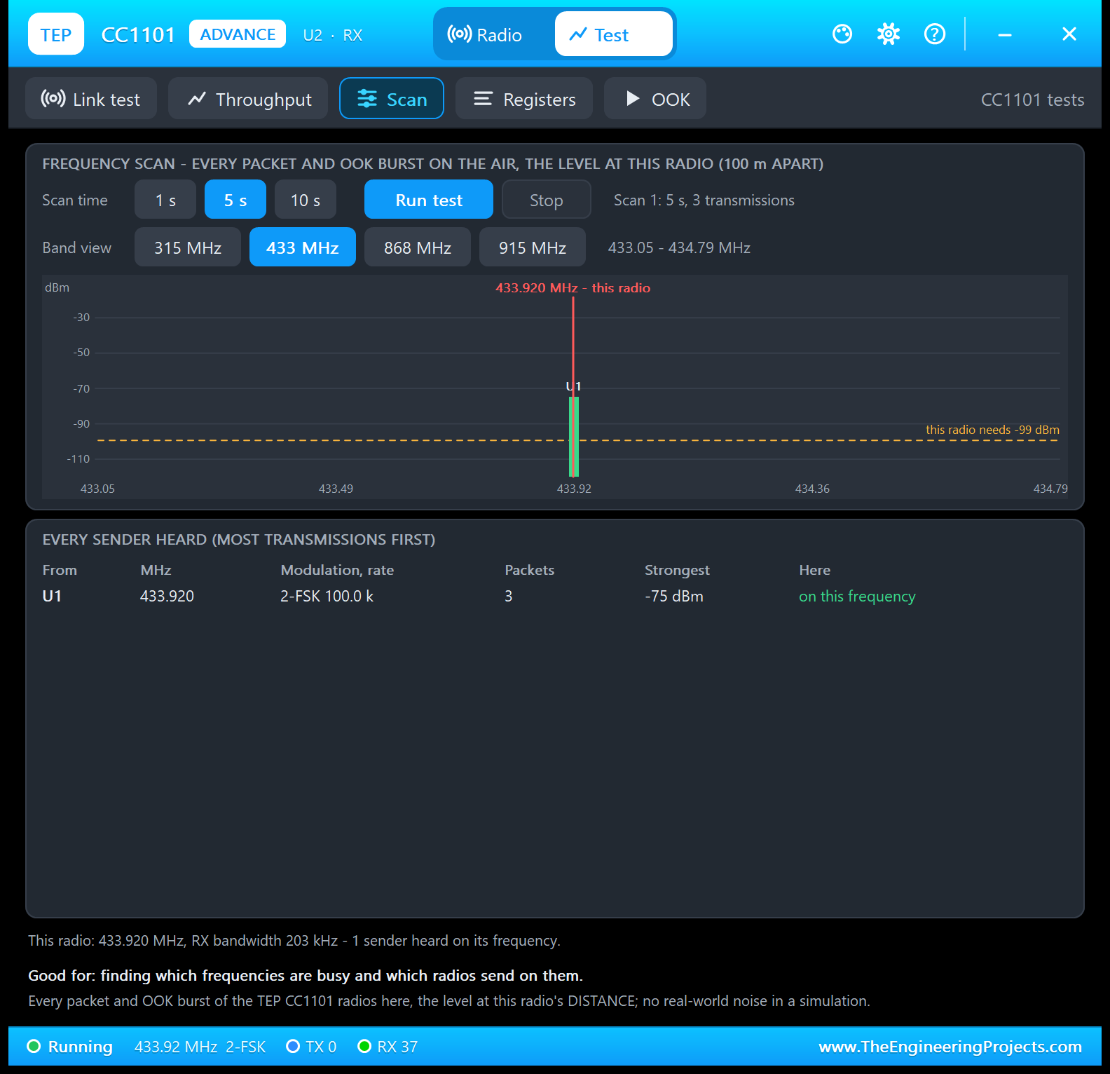
One bar at 433.920 MHz, marked in red as this radio's frequency: 3 packets from U1, 2-FSK 100 kBaud, at -75 dBm, far above the "needs -99 dBm" line, and "on this frequency" in the list. Senders on other frequencies are listed, too. Good for: finding which frequencies are busy.
4. Registers: What Did Your Sketch Write?
This tool reads the registers live, as SmartRC's SpiReadReg would, decodes them and lists the Arduino's last SPI commands:
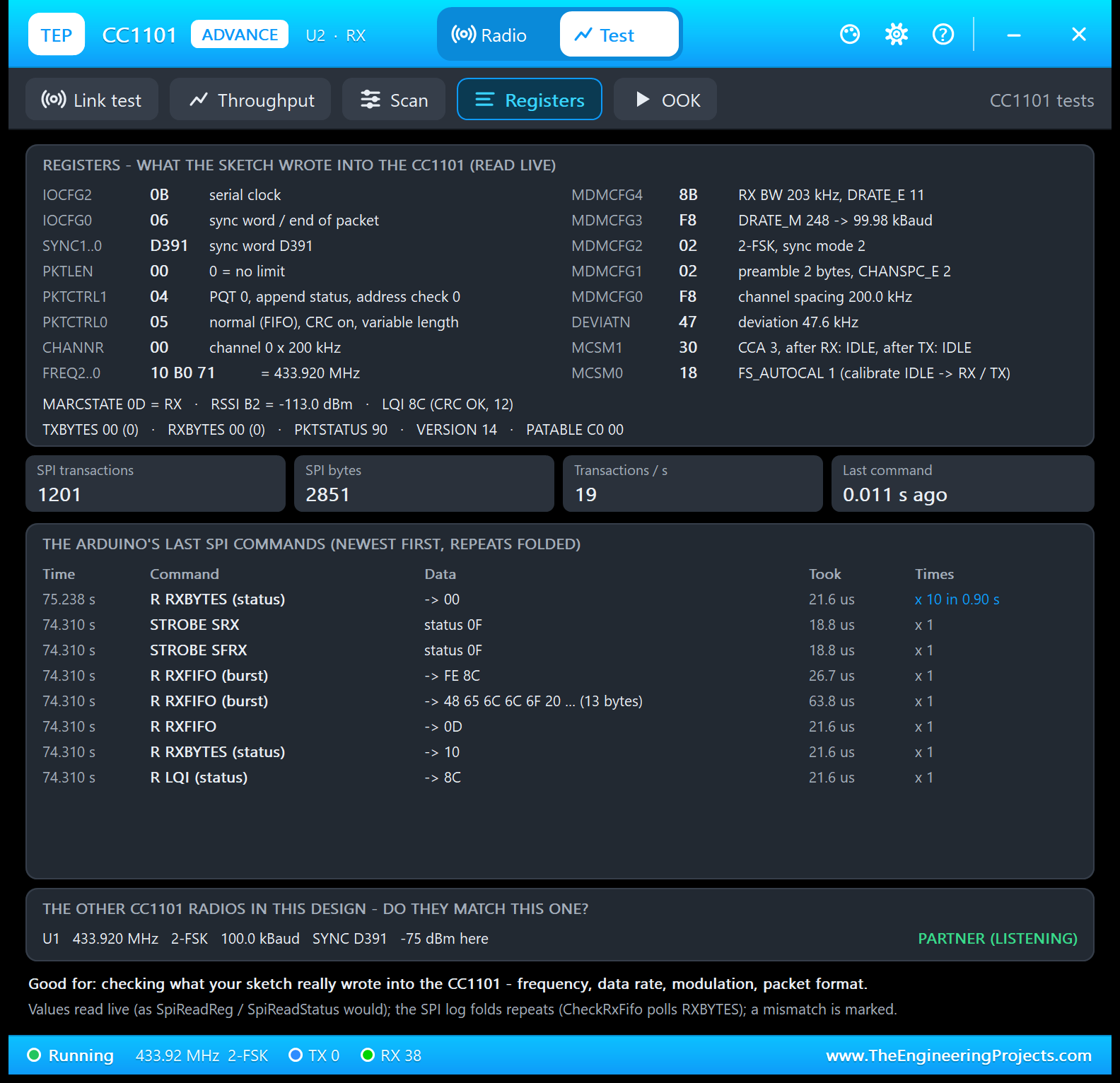
- FREQ2..0 10 B0 71 = 433.920 MHz: 0x10B071 = 1,093,745 steps of 26 MHz / 65536.
- MDMCFG4 8B, MDMCFG3 F8, DEVIATN 47: RX bandwidth 203 kHz, 99.98 kBaud, deviation 47.6 kHz; MDMCFG2 02: 2-FSK, sync mode 2.
- PKTCTRL0 05, PKTCTRL1 04: FIFO mode, CRC on, variable length, status appended, no address check.
- MCSM0 18: FS_AUTOCAL 1, calibrate on the way from IDLE to RX or TX: the 809 + 90 us of the Throughput tool.
- MARCSTATE 0D = RX, LQI 8C (CRC OK, 12), PATABLE C0: listening, the quality of the last packet and the +10 dBm power byte.
Read the SPI log from the bottom up, and you watch one packet being read: RXBYTES 10 (16 bytes waiting), RXFIFO 0D (length 13), 48 65 6C 6C 6F 20 ("Hello " in ASCII), FE 8C (the appended RSSI and LQI; FE is -75 dBm), then SFRX and SRX to listen again. The newest row is folded, RXBYTES x 10 in 0.90 s: the receiver sketch's check every 100 ms. At the bottom, U1 is marked PARTNER (LISTENING); a mismatch would be marked. Good for: checking what your sketch really wrote.
5. OOK: The Pulse Train of a Remote Code
The last tool shows the newest burst of the asynchronous mode: the first frame and the whole burst as waveforms, the pulse count, the short pulse T and an rc-switch protocol 1 decoder. Here is the code 5393 from my SNIFF and OOK test (see the Simulation Results below):
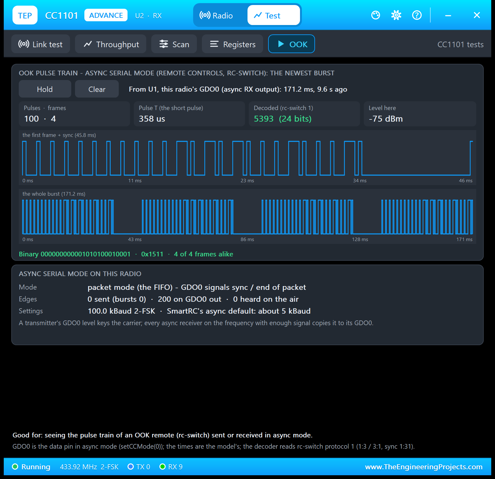
The burst came from U1 and appeared on the GDO0 of U2: 171.2 ms, 100 pulses in 4 frames of 45.8 ms, at -75 dBm. T is 358 us; the sketch asks for 350 us, and the UNO's pin writes add a few microseconds. The decoder reads 5393 (24 bits), 0x1511, in 4 of 4 frames alike; glitches shorter than T / 4 are ignored. Good for: seeing the pulse train of an OOK remote.
Settings and Help
The gear opens Settings: theme (TEP Dark or Light), text size, open the panel at Run and window size, saved for your Windows user.
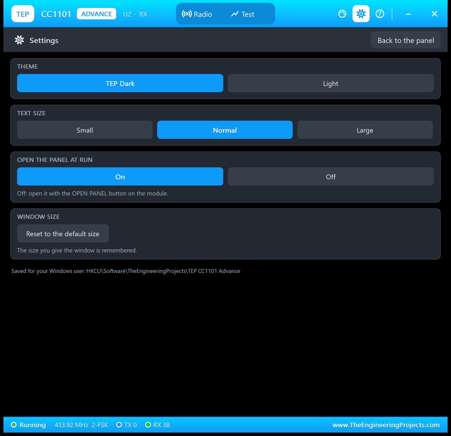
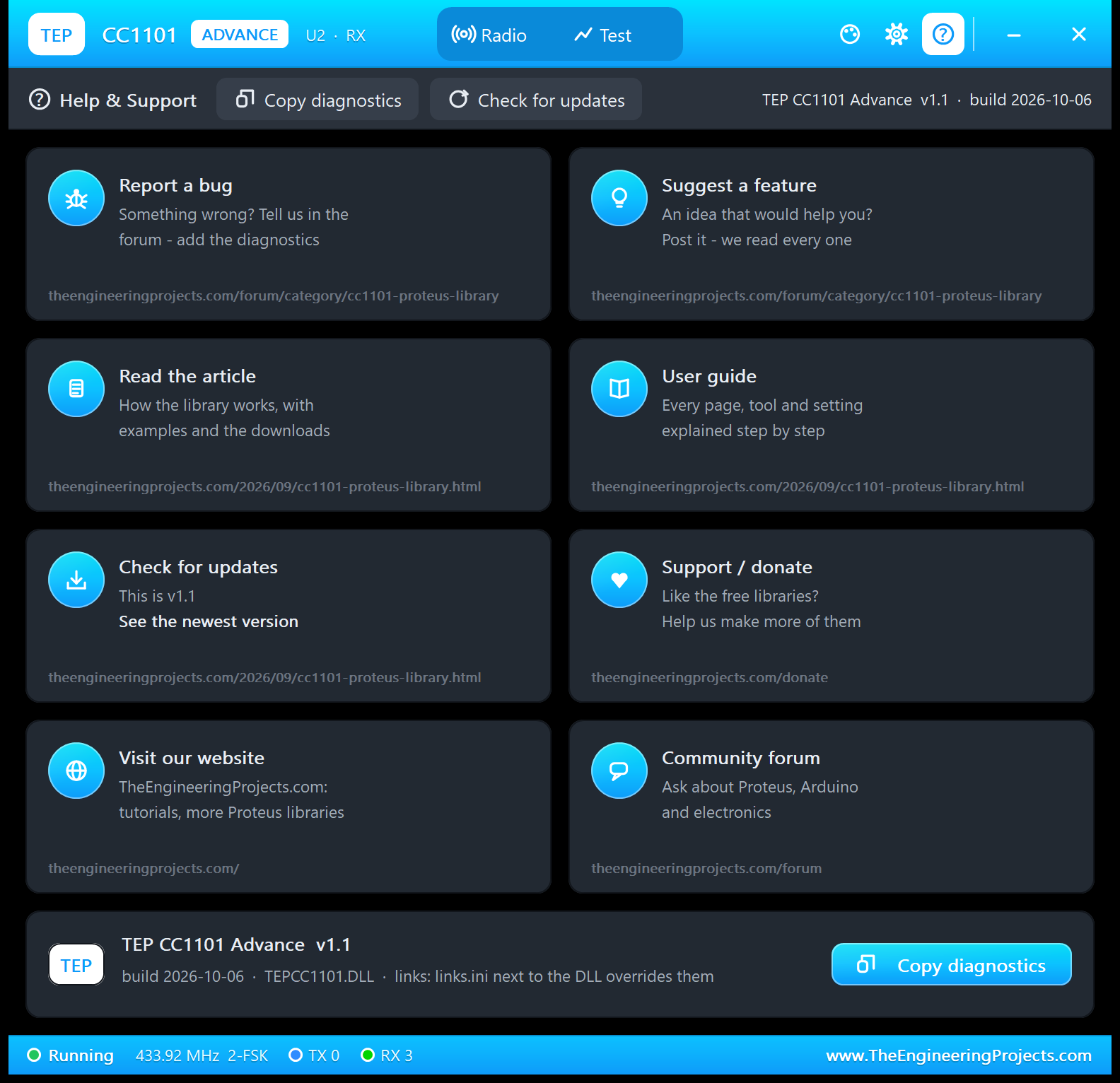
The ? icon opens Help & Support: eight cards and Copy diagnostics for a bug report. Report a bug and Suggest a feature open the CC1101 board of our forum; Read the article, User guide and Check for updates open this article; the other three open the donate page, our website and the forum. A links.ini next to the DLL can change the links.
CC1101 Wireless Link with Arduino in Proteus
Open CC1101-ArduinoUnoV3.pdsprj from the Proteus Simulation folder, with the .hex files and the DLLs beside it. It has two Arduino UNOs from our Arduino Library for Proteus V3.0 (the first image shows the whole circuit):
- NODE 1 - TRANSMITTER: UNO 1 (ARD1) with
CC1101_Transmitter.hex, the CC1101 Simple (U1) and Serial Monitor U3. - NODE 2 - RECEIVER: UNO 2 (ARD2) with
CC1101_Receiver.hex, the CC1101 Advance (U2) and Serial Monitor U4.
Wiring
| From | To | Why |
|---|---|---|
| CC1101 VCC / GND | Supply / ground | Power (+5 V in the simulation; a real module needs 3.3 V) |
| CC1101 SCK | Arduino D13 | SPI clock |
| CC1101 MISO | Arduino D12 | Data from the radio |
| CC1101 MOSI | Arduino D11 | Data to the radio |
| CC1101 CSN | Arduino D10 | Chip select |
| CC1101 GDO0 | Arduino D2 | Packet signal; the data pin in async mode |
| CC1101 GDO2 | Arduino D9 | Not used by the sketches |
| Serial Monitor RXD / TXD / GND | Arduino D1 / D0 / ground | Shows what the Arduino prints, sends what you type |
D11, D12 and D13 are the UNO's hardware SPI pins, which SmartRC sets up by itself (see our Introduction to Arduino UNO). No wire joins the two nodes: they share one simulated air.
The Arduino Code
Both sketches use the unmodified SmartRC-CC1101-Driver-Lib (its object is ELECHOUSE_cc1101). The settings live in variables, so FREQ, RATE and MOD can change them:
float mhz = 433.92, kbaud = 99.97;
byte modulation = 0;                     // 0 2-FSK, 1 GFSK, 2 ASK/OOK, 3 4-FSK, 4 MSK (SmartRC's numbers)
99.97 kBaud is SmartRC's own packet-mode rate, printed as "100 kBaud". setRadio() writes the packet-mode settings at start-up and after every OOK burst or SNIFF:
  ELECHOUSE_cc1101.setCCMode(1);         // packet mode
  ELECHOUSE_cc1101.setModulation(modulation);
  ELECHOUSE_cc1101.setMHZ(mhz);
  ELECHOUSE_cc1101.setDRate(kbaud);
  ELECHOUSE_cc1101.setSyncMode(2);       // 16/16 sync word bits
  ELECHOUSE_cc1101.setCrc(1);
There is no setPA(): SmartRC's default gives +10 dBm at 433 MHz (PATABLE C0). In setup(), the order matters:
  ELECHOUSE_cc1101.Init();               // Init() first: it sets up the SPI pins that getCC1101() uses
  if (!ELECHOUSE_cc1101.getCC1101()) {
    Serial.println(F("CC1101 not responding - check the SPI wiring and power"));
    while (true) {}
  }
  ELECHOUSE_cc1101.setGDO0(GDO0_PIN);
  setRadio();
SmartRC's own examples call getCC1101() before Init() and can report an error on a good module. While AUTO is ON, the transmitter sends the v1.0 message every 2 s:
  if (autoSend && millis() - lastSend >= 2000) {
    lastSend = millis();
    char message[32];
    snprintf(message, sizeof message, "Hello TEP #%d", counter++);
    send(message);
  }
Every packet goes out through SendData():
ELECHOUSE_cc1101.SendData(message); // returns when GDO0 signals the end of the packetBoth sketches watch for packets the same way: CheckReceiveFlag() catches the GDO0 pulse, and if the loop missed it while printing, a check every 100 ms finds the packet in the RX FIFO with the radio back in IDLE:
bool packetWaiting() {
  if (ELECHOUSE_cc1101.CheckReceiveFlag()) return true;
  if (millis() - lastFifoCheck < 100) return false;
  lastFifoCheck = millis();
  return (ELECHOUSE_cc1101.SpiReadStatus(CC1101_RXBYTES) & 0x7F) && ELECHOUSE_cc1101.SpiReadStatus(CC1101_MARCSTATE) == 0x01;
}
The receiver reads RSSI and LQI before ReceiveData(), which restarts RX:
int receive(int& rssi, byte& lqi) {
  if (ELECHOUSE_cc1101.CheckCRC()) {
    rssi = ELECHOUSE_cc1101.getRssi();   // read before ReceiveData() restarts RX
    lqi = ELECHOUSE_cc1101.getLqi() & 0x7F;
    byte length = ELECHOUSE_cc1101.ReceiveData(buffer);
A PING is answered before anything is printed, so the round trip measures the radios, not the 9600-baud Serial port:
  bool ping = strcmp((char*)buffer, "PING") == 0;
  if (ping) transmit("PONG");            // answer first (the round trip), print afterwards
The OOK command plays the rc-switch code on GDO0 in asynchronous mode. Note the 1 ms wait after SetTx(): the CC1101 calibrates for about 0.8 ms first, and a pulse written sooner is lost, on real hardware too:
  ELECHOUSE_cc1101.setCCMode(0);         // asynchronous serial mode: GDO0 is the data input
  ELECHOUSE_cc1101.setModulation(2);     // ASK/OOK
  ELECHOUSE_cc1101.setMHZ(mhz);
  ELECHOUSE_cc1101.SetTx();
  delayMicroseconds(1000);               // the CC1101 calibrates (about 0.8 ms) before it sends - a pulse written sooner is lost
  pinMode(GDO0_PIN, OUTPUT);
  for (byte r = 0; r < 4; ++r) {
    for (int b = 23; b >= 0; --b) {
      bool one = (code >> b) & 1;
      digitalWrite(GDO0_PIN, HIGH); delayMicroseconds(one ? 1050 : 350);
      digitalWrite(GDO0_PIN, LOW);  delayMicroseconds(one ? 350 : 1050);
    }
    digitalWrite(GDO0_PIN, HIGH); delayMicroseconds(350);
    digitalWrite(GDO0_PIN, LOW);  delay(11);                   // 31 T
  }
SNIFF does the opposite on the receiver: it measures the pulse widths on GDO0 by polling (no interrupt needed) and sorts each pulse pair into a 0 or a 1:
  ELECHOUSE_cc1101.setCCMode(0);         // asynchronous serial mode: GDO0 is the data output
  ELECHOUSE_cc1101.setModulation(2);     // ASK/OOK
  ELECHOUSE_cc1101.setMHZ(mhz);
  ELECHOUSE_cc1101.SetRx();
if (about(h, T, 1) && about(l, T, 3)) { value <<= 1; ++bits; }
else if (about(h, T, 3) && about(l, T, 1)) { value = (value << 1) | 1; ++bits; }To change a sketch, install SmartRC-CC1101-Driver-Lib, export the compiled binary and load the new HEX file into its UNO; see How to get the HEX file from Arduino. New to Arduino? Start with our Arduino Tutorial for Beginners.
Serial Monitor Commands
| Command | What it does |
|---|---|
| HELP | The command list |
| STATUS | Frequency, modulation, data rate, CRC, chip check and counters |
| SEND <text> | A message to the other node now (up to 34 characters) |
| PING | The other node answers PONG; prints the round trip time |
| FREQ <MHz> | For example FREQ 868.3: 300 - 348, 387 - 464 or 779 - 928 MHz (type it on both monitors) |
| RATE <kBaud> | For example RATE 1.2: 0.6 - 500 kBaud (both monitors) |
| MOD <FSK|GFSK|OOK|4FSK|MSK> | The modulation (both monitors) |
| AUTO <ON|OFF> | Node 1 only: the Hello TEP message every 2 s |
| OOK <code> | Node 1 only: a 24-bit remote code (0 - 16777215), rc-switch protocol 1, 350 us, 4 times |
| SNIFF [seconds] | Node 2 only: listen for an OOK remote (1 - 30 s, default 5) and decode it |
How to Run the Demo
- Press Run. Both Serial Monitors (9600 baud) and the pop-up of U2 open, and the Hello packets start.
- Type PING and STATUS on U3.
- Click 1 km on the panel of U1, then type RATE 1.2 on both monitors. Back: 100 m and RATE 100.
- Type SNIFF on U4 and, within 5 s, OOK 5393 on U3.
- Run the five tools on the Test tab of U2.
CC1101 Proteus Simulation Results
The Serial Monitor in Its Simple Interface
Both monitors in this demo run in the Simple interface of our TEP Serial Monitor, and every monitor screenshot in this article shows them that way. Only the log, the send box and one slim toolbar row stay visible (baud rate, follow, pause, search and clear). The header, the quick buttons and the status bar are hidden, so the window stays small next to your schematic.
- Switch to it: right-click the log and choose Simple interface, or press Ctrl+Shift+U.
- Back to the full view: click the corner button (the expand arrows at the top right), press Esc or Ctrl+Shift+U, or right-click and choose Full interface.
- Your choice is remembered.
Type commands such as PING, SNIFF or OOK 5393 in the send box and press Enter; the quick buttons come back with the full view. RXD2, the monitor's second input, is not used: the CC1101 talks SPI and has no serial line to watch. Read all about the monitor in TEP Serial Monitor Advance for Proteus.
Start-Up: Hello TEP Arrives
After Run, both monitors print their banners, and a packet goes out every 2 s. The first lines of U3 and U4 in my run:
TEP CC1101 Transmitter Demo v1.1
CC1101 ready: 433.92 MHz, 2-FSK, 100 kBaud, CRC on
Type HELP in the Serial Monitor for the commands
Sent: Hello TEP #0
Sent: Hello TEP #1
TEP CC1101 Receiver Demo v1.1
Listening: 433.92 MHz, 2-FSK, 100 kBaud, CRC on
Type HELP in the Serial Monitor for the commands
Received: Hello TEP #0 RSSI -75 dBm LQI 12
Received: Hello TEP #1 RSSI -75 dBm LQI 12Every packet arrives at -75 dBm with LQI 12, the 100 m numbers. Every 10 s, U4 adds a link line such as "Link (10 s): 5 received, 0 CRC errors, 0 sent", and U3 its own, such as "Link (10 s): 5 sent, 0 received".
Typing Commands: PING, PONG and STATUS
Now U3, the transmitter. I typed PING, pressed Enter, then STATUS. Lines you send carry a blue TX tag, the Arduino's lines a green RX tag:
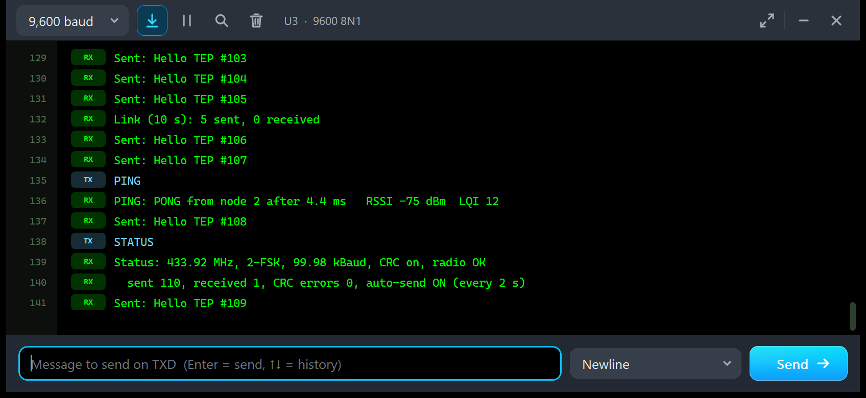
Sent: Hello TEP #107
PING
PING: PONG from node 2 after 4.4 ms   RSSI -75 dBm  LQI 12
Sent: Hello TEP #108
STATUS
Status: 433.92 MHz, 2-FSK, 99.98 kBaud, CRC on, radio OK
  sent 110, received 1, CRC errors 0, auto-send ON (every 2 s)
Sent: Hello TEP #109
PONG came back after 4.4 ms: two packets, each about 1.8 ms with its calibration, plus the SPI time of both UNOs. STATUS reads the settings back from the chip ("radio OK" comes from getCC1101()). The counters tell my run: 110 sent (Hello #0 to #108 plus the PING) and 1 received, the PONG. On U4, the PING arrives like any message:
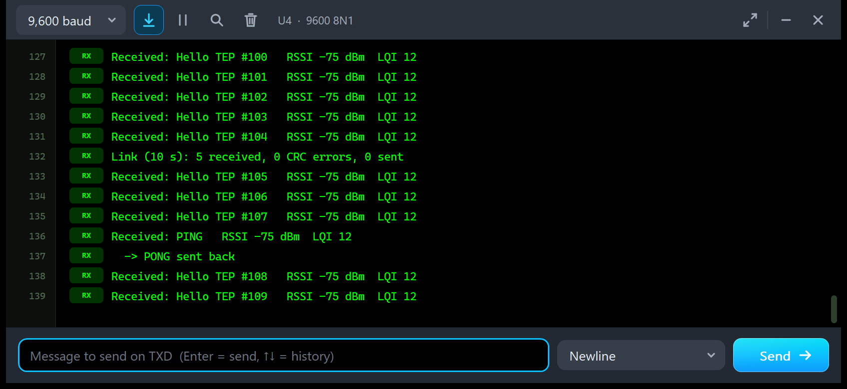
Received: Hello TEP #107   RSSI -75 dBm  LQI 12
Received: PING   RSSI -75 dBm  LQI 12
  -> PONG sent back
Received: Hello TEP #108   RSSI -75 dBm  LQI 12
Sniff and Replay a 433 MHz Remote: SNIFF and OOK
Here comes my favourite experiment. On U4, type SNIFF: node 2 switches to asynchronous OOK mode and listens for 5 s. Within those 5 s, type OOK 5393 on U3:
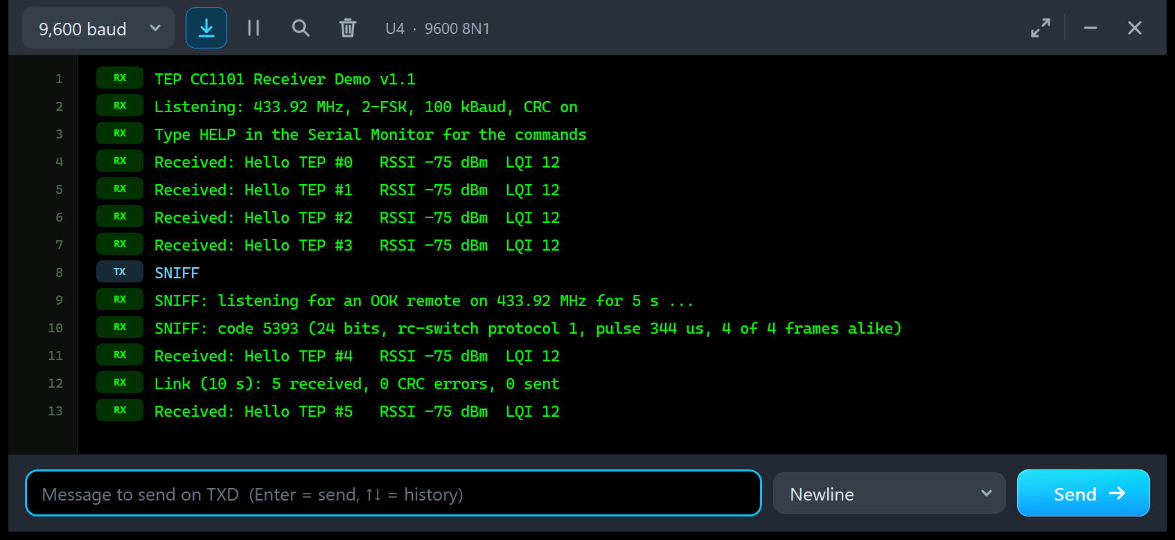
SNIFF
SNIFF: listening for an OOK remote on 433.92 MHz for 5 s ...
SNIFF: code 5393 (24 bits, rc-switch protocol 1, pulse 344 us, 4 of 4 frames alike)
Received: Hello TEP #4   RSSI -75 dBm  LQI 12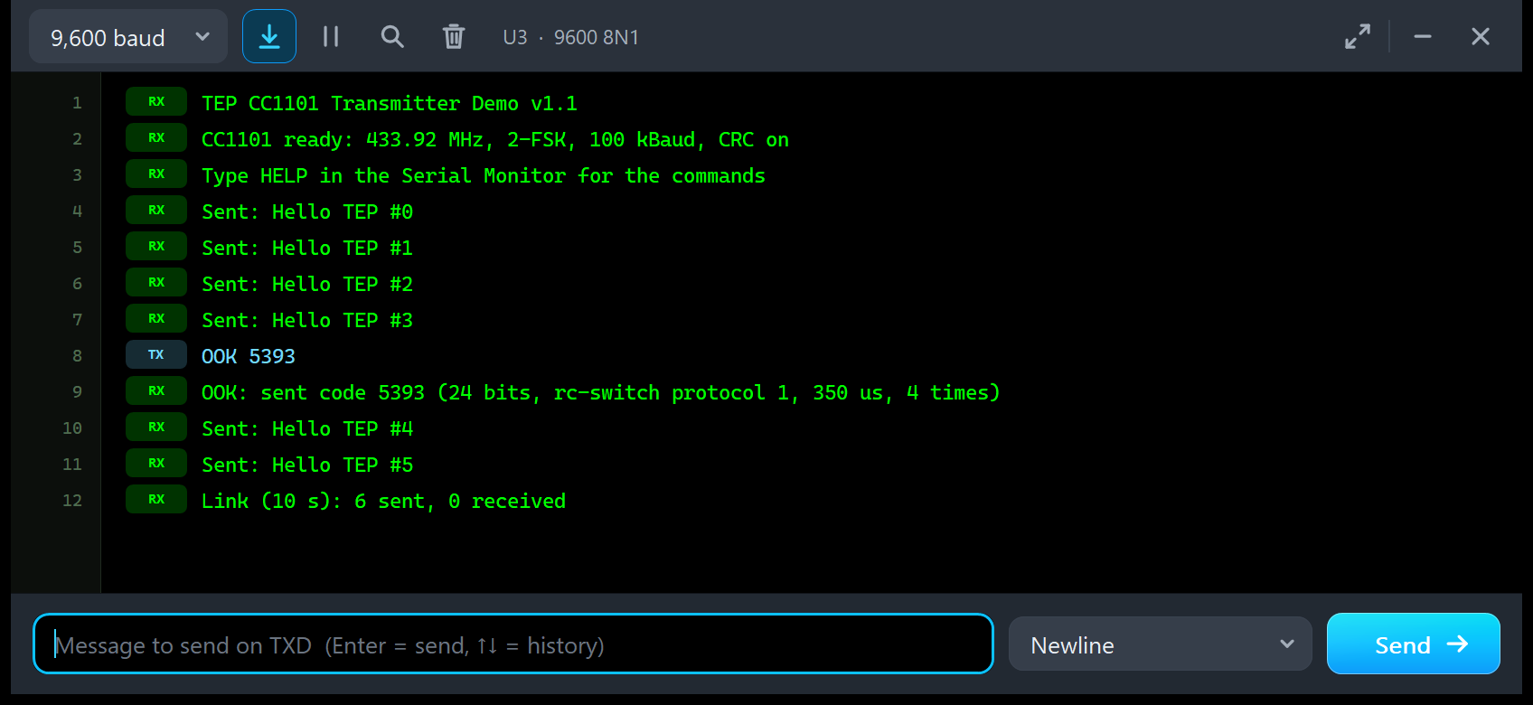
OOK 5393
OOK: sent code 5393 (24 bits, rc-switch protocol 1, 350 us, 4 times)
Sent: Hello TEP #4
U3 played the code four times and went back to packet mode. U4 measured the pulses on its GDO0 and decoded the same 24-bit code, 4 of 4 frames alike, and Hello TEP #4 arrives as usual. While U1 sends the burst, its panel shows TX - SENDING (ASYNC), with ASK/OOK at SmartRC's asynchronous default of about 5 kBaud:
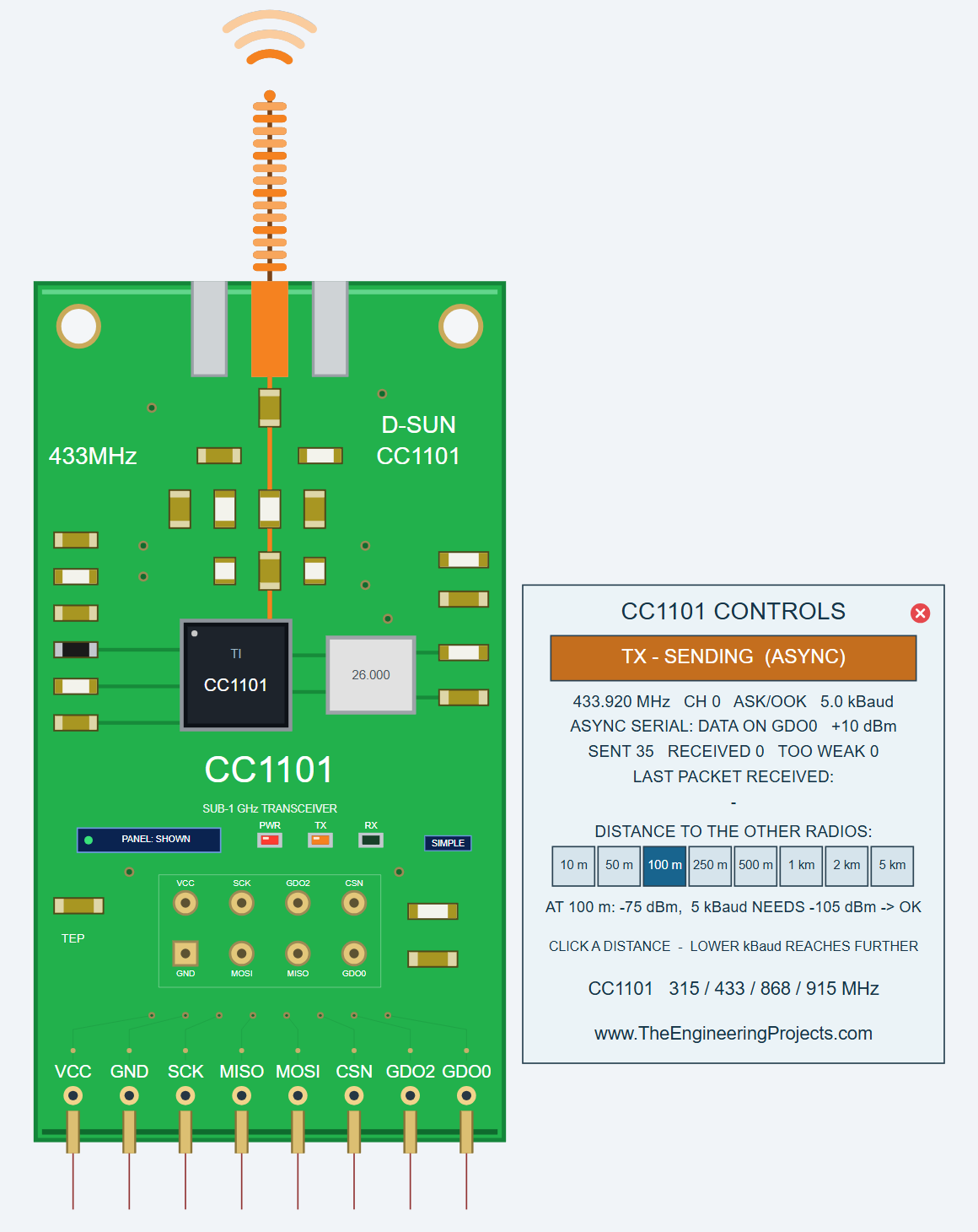
This is how people read and copy a 433 MHz remote with a real CC1101: SNIFF shows the code, and OOK sends it again. Use it only with your own devices.
Troubleshooting
- "CC1101 not responding - check the SPI wiring and power": check SCK D13, MISO D12, MOSI D11, CSN D10 and VCC / GND, and TEPCC1101.DLL in MODELS and beside the project.
Init()must come beforegetCC1101(). - Nothing received: both nodes need the same frequency, modulation, data rate, sync word and packet mode (
setCCMode(1)), and both DISTANCE settings count (100 kBaud ends at about 640 m). The Registers tool lists what does not match. - SNIFF prints "nothing received": start SNIFF first, then send the code within its time, on the same frequency.
- No monitor window or no pop-up: a DLL is missing; click OPEN MONITOR on the monitor part or OPEN PANEL on the board, or turn "Open the panel at Run" back on.
- No red X / the old blue board: replace the LIB, delete TEPCC1101.IDX and re-pick the part.
- Your own sketch: hardware SPI and polling GDO0 or INT0 on D2 work in Proteus 8.5; only pin-change interrupts never fire there, so SoftwareSerial cannot receive (not needed here).
Things to Know Before Using a Real CC1101
The demo sketches use only SmartRC-CC1101, so they run on two real UNOs and modules, too. Keep in mind:
- 3.3 V only: the supply range is 1.8 - 3.6 V, so feed VCC from 3.3 V, never from 5 V. In the simulation, VCC goes to the +5 V terminal, because the model only checks that it is powered.
- Level shifting: the CC1101's pins are NOT 5 V tolerant. On a 5 V Arduino UNO, Nano or Mega, put a level shifter (for example a TXS0108E, or resistor dividers on SCK, MOSI, CSN and GDO0 when the UNO drives it) between the board and the module. 3.3 V boards (ESP32, ESP8266, Arduino Pro Mini 3.3 V) connect directly.
- A capacitor: put 10 uF across VCC and GND near the module; the UNO's 3.3 V pin is weak for the 30 mA TX peaks.
- One module, one band: a module is built for ONE band (its matching network and spring), so a 433 MHz module works badly at 868 or 915 MHz, even though the chip tunes there. Keep the spring straight and clear of metal.
- Check the header: D-SUN and Ebyte modules order their pins differently; follow the print on your board.
- Legal bands and duty cycle: use only the frequencies and powers allowed where you live. Europe (ERC/REC 70-03): 433.05 - 434.79 MHz at 10 mW with up to 10 % duty cycle, 868.0 - 868.6 MHz at 25 mW with up to 1 %; USA (FCC part 15): 902 - 928 MHz, and 315 MHz for remote controls with time limits.
- Remote codes: wait about 1 ms after
SetTx()before the first pulse, as our OOK command does, and replay only the codes of your own devices.
Limitations of the Simulation
- Not modelled: collisions of simultaneous transmitters, random packet loss (a link is OK, at the edge with a CRC error, or too weak), fading, multipath and interference, wake-on-radio, the FIFO filling during a packet, clock outputs on GDO, SPI timing violations and the supply voltage.
- The range is a teaching model (exponent 3 beyond 1 m); real range depends on your antennas and surroundings.
- The model is our own implementation, written from the Texas Instruments CC1101 data sheet; it contains no SmartRC code.
- Tested in Proteus 8.5 SP0 on 6 Oct 2026 (the demo, the SNIFF / OOK relay and every Proteus screenshot here) and with 981 automatic PC checks, all passed, 38 of them with the unmodified SmartRC-CC1101 library and 53 with the real v1.1 sketches. The images marked "PC render" were drawn by the model's own code. Proteus 7 is not supported.
For 2.4 GHz, see our nRF24L01 Library for Proteus and nRF24L01+PA+LNA Library for Proteus. For other 433 MHz radios, try our HC-12 Library for Proteus, SX1278 LoRa Library for Proteus or RFM69HCW Library for Proteus.
So, that was all about the CC1101 Library for Proteus V1.1. I hope the DISTANCE buttons, the glowing spring, the five test tools and the SNIFF and OOK experiment make sub-1 GHz radio much easier to understand, so your wireless project works the first time you wire two real modules. If you use the CC1101 Library for Proteus in a project, please share your feedback in the comments or in our forum, and if you have any questions, ask in the comments and I will help you out. Till the next tutorial, take care and have fun!

Comments
0