


NEMA 17 Closed-Loop Stepper Library for Proteus Simulation


Hello friends, I hope you all are doing great. Today, I am going to share the new NEMA 17 Closed-Loop Stepper Library for Proteus Simulation, the 44th library of our motor series. If you have searched for a Proteus simulation of a closed-loop stepper motor, or wondered why a stepper loses steps and how an encoder stops it, this library answers both: a NEMA 17 stepper with a driver board on its back that reads the shaft with a magnetic encoder and never forgets where it is.
NEMA 17 Closed-Loop Stepper Library for Proteus Simulation
Latest version: V1.0 (November 2026, this tutorial)
Helping Tools
- Serial Monitor Advance: a serial terminal window for the UART of your board
- Serial Monitor Expert: the serial monitor with extra debugging tools
- LCD Library for Proteus V3.0: 16x2, 20x4 and I2C LCDs to show your readings
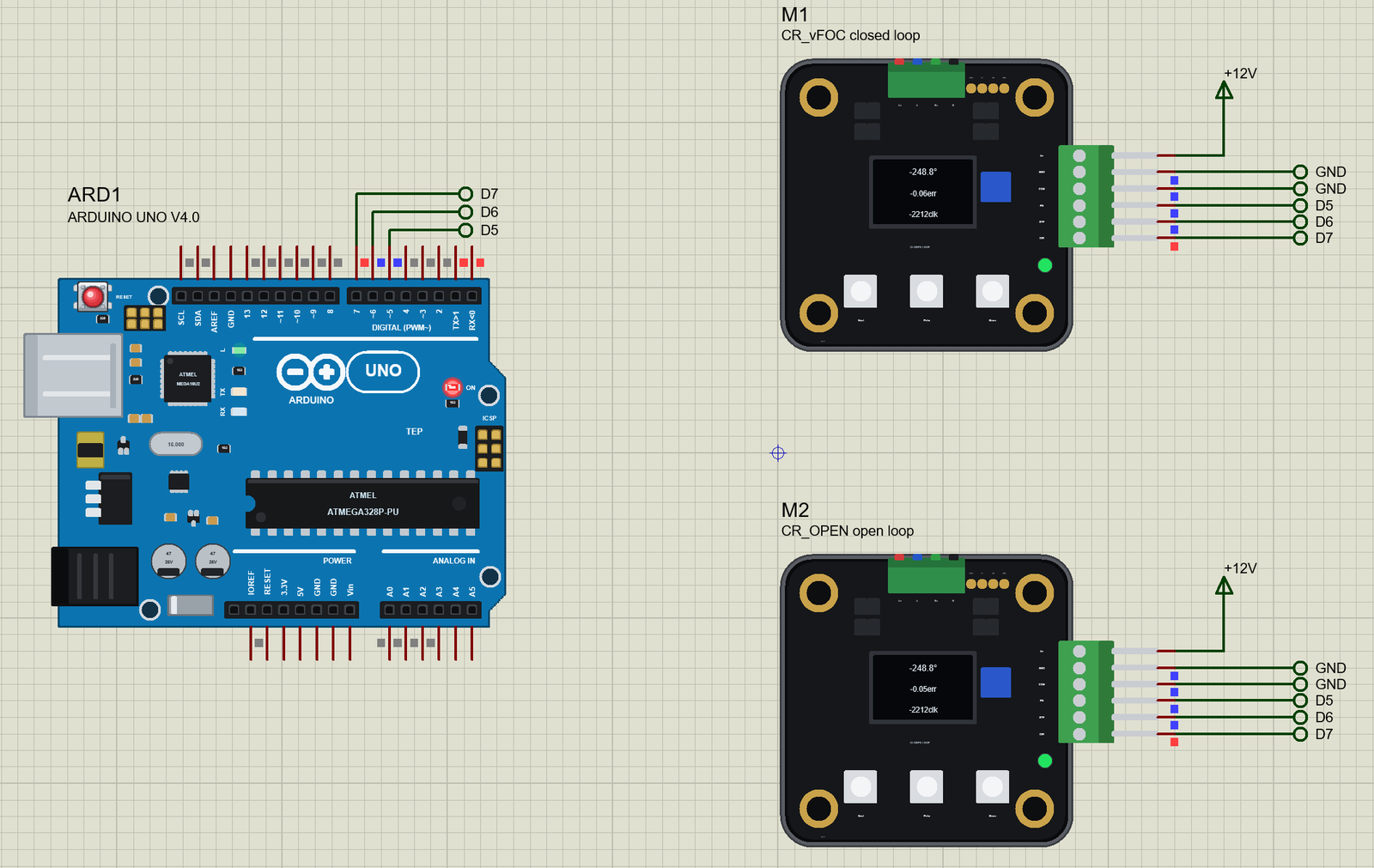
Our library brings that motor into your Proteus simulation at its true size, the 42 mm motor's end with the black driver board, its OLED, three keys and the green terminal; at run time the OLED shows the shaft angle, the error and the pulses received, as on the real board. The simulation model runs both ways the board can: closed loop, where the encoder sets the current from the load, and open loop, an ordinary stepper at a fixed current. In the demo an Arduino drives one of each on the same three wires, and when a load is put on both, the difference is impossible to miss.
NOTICE: Our team has put a lot of effort into these small parts: the bodies, the animation and the pop-ups are all our own design, and you get them free. Your feedback is the fuel that keeps us going, so please tell us what you think in the comments below or in the Motor Driver board of our forum. And if our free libraries help you, you can buy us a coffee. So, let's get started with the NEMA 17 Closed-Loop Stepper Library for Proteus Simulation:
What is a Closed-Loop Stepper Motor?
An ordinary stepper motor moves one step for every pulse it receives, and the controller simply counts the pulses it has sent. Nothing checks that the motor really moved. If the load is too heavy, or the motor is asked to accelerate too fast, the rotor falls behind its field and slips: the controller still thinks the axis is where it sent it, but it is not. On a 3D printer that is a shifted layer; on a CNC machine, a ruined part.
A closed-loop stepper adds the missing check. A magnetic encoder on the motor's shaft, read by a small processor on the driver board, measures the real angle thousands of times a second. The board still takes the same STEP and DIR pulses, so any controller can drive it, but it compares the pulses with the encoder and sets the coil current from the difference. A small error asks for a small current; a heavy load gets up to 3 A. The open-source class of boards we drew for this library adds field-oriented control, an OLED and three keys, and fits behind any 42 mm motor.
| The NEMA 17 closed-loop stepper (this class) | |
|---|---|
| Motor | 42 x 40 mm, 1.8 deg (200 full steps a turn), 1.7 A, 1.5 ohm, 2.8 mH, 0.40 N.m holding |
| Driver supply | 7 to 28 V |
| Current | 0 to 3000 mA (closed loop sets it from the load) |
| Microsteps | 1 to 256 (16 by default: 3200 pulses a turn) |
| Encoder | 14-bit magnetic (16384 counts a turn) |
| Inputs | STP, DIR, EN (opto inputs, 3.3 to 28 V above COM) |
How the Encoder Loop Keeps the Steps
Inside, a hybrid stepper is a motor with 50 rotor teeth. The field of the two coils turns one electrical turn for every 7.2 degrees of the shaft, four full steps. In open loop the driver points the field at the commanded position with a fixed current, and the rotor's teeth are pulled after it like a compass needle. The angle between them, the load angle, grows with the load; the torque grows with its sine and is largest at 90 electrical degrees. Past that the rotor drops a whole electrical turn behind: four full steps lost in a moment, and they never come back.
Closed loop works differently. The driver knows exactly where the rotor is, so it always puts the field 90 electrical degrees ahead of the teeth, where each ampere gives the most torque, and it sets the size of the current from the error between the pulses and the encoder. If a load makes the shaft fall behind, the error grows, the current grows and the shaft catches up. The motor can lag for a moment, but it cannot lose steps, and with no load it holds with almost no current, so it runs cool and quiet.
Features of the NEMA 17 Closed-Loop Stepper Library for Proteus Simulation
- The motor at true scale: the 42 mm motor's end with the driver board, its mounting rings, the motor connector, the OLED, the keys, the LED and the terminal; at run time the OLED shows the angle, the error and the pulses received.
- Two modes: CR_vFOC, closed loop with the encoder; CR_OPEN, open loop at the MA current, which slips four full steps at a time under overload.
- The real limits: up to 3 A, and what the supply voltage can push against the motor's back-EMF; the torque the driver can give falls with the speed.
- PROTECT: in closed loop, a blocked shaft switches the motor off, with "Wrong Protect" on the OLED; EN off, then on, restarts it.
- The shaft: the rotor's inertia plus the INERTIA property, the detent at the full steps, friction and the LOAD property as a brake; the pop-up's chips add 0.1 or 0.3 N.m or block it.
- A pop-up: the shaft against the target on a dial, the error and the current over 2 s, the torque against the speed, graphs, an event log and a check page.
- A complete package: about 1.2 MB with the library, our Arduino UNO V4.0 and the demo, without the source code of the model.
The NEMA 17 Closed-Loop Stepper in Proteus
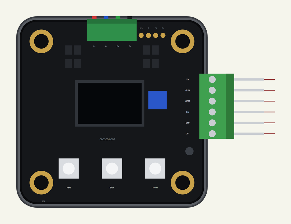
The device is NEMA17CLTEP in TEPNEMA17CL.LIB, under Electromechanical > Motors, with the prefix M and the mixed model TEPNEMA17CL.DLL. Search NEMA17CL in Pick Devices. Its terminal on the right has V+ and GND for the 7 to 28 V supply, COM, the common of the opto inputs, which goes to the controller's ground, and EN, STP and DIR. The properties follow the real board's menu: MODE (CR_vFOC or CR_OPEN), MA (the open-loop current, 1200 mA), MSTEP (16), EN (L: low enables, H, or Hold), DIR (CW or CCW), PROTECT (Disable or Enable), plus LOAD and INERTIA for the mechanics.
Download NEMA 17 Closed-Loop Stepper Library for Proteus Simulation
Click the button below to download NEMA-17-Closed-Loop-Stepper-Library-for-Proteus-v1.0.zip (about 1.2 MB, without the source code of the models):
NEMA 17 Closed-Loop Stepper Library for Proteus V1.0- README.txt: installation, the demo, the wiring, troubleshooting and the limits of the simulation.
- Proteus Library Files:
TEPNEMA17CL.LIBandArduinoV4TEP.LIB. - Proteus Model Files:
TEPNEMA17CL.DLLandTEPARDUINO.DLL. - Arduino Code: the demo sketch.
- Proteus Simulation: the demo project, its HEX file and copies of the DLLs.
No Proteus yet? Read How to Download and Install Proteus 7 and 8. New to libraries? Follow How to Install a New Library in Proteus.
How to Install NEMA 17 Closed-Loop Stepper Library for Proteus Simulation
- Close Proteus and extract the whole zip file, for example to your Desktop.
- Copy the files from Proteus Library Files into the LIBRARY folder of Proteus.
- Copy the files from Proteus Model Files into the MODELS folder.
- Delete
TEPNEMA17CL.IDXfrom the LIBRARY folder if it is there. - Start Proteus, press P and search for NEMA17CL.
Proteus Simulation of the Closed-Loop Stepper with Arduino
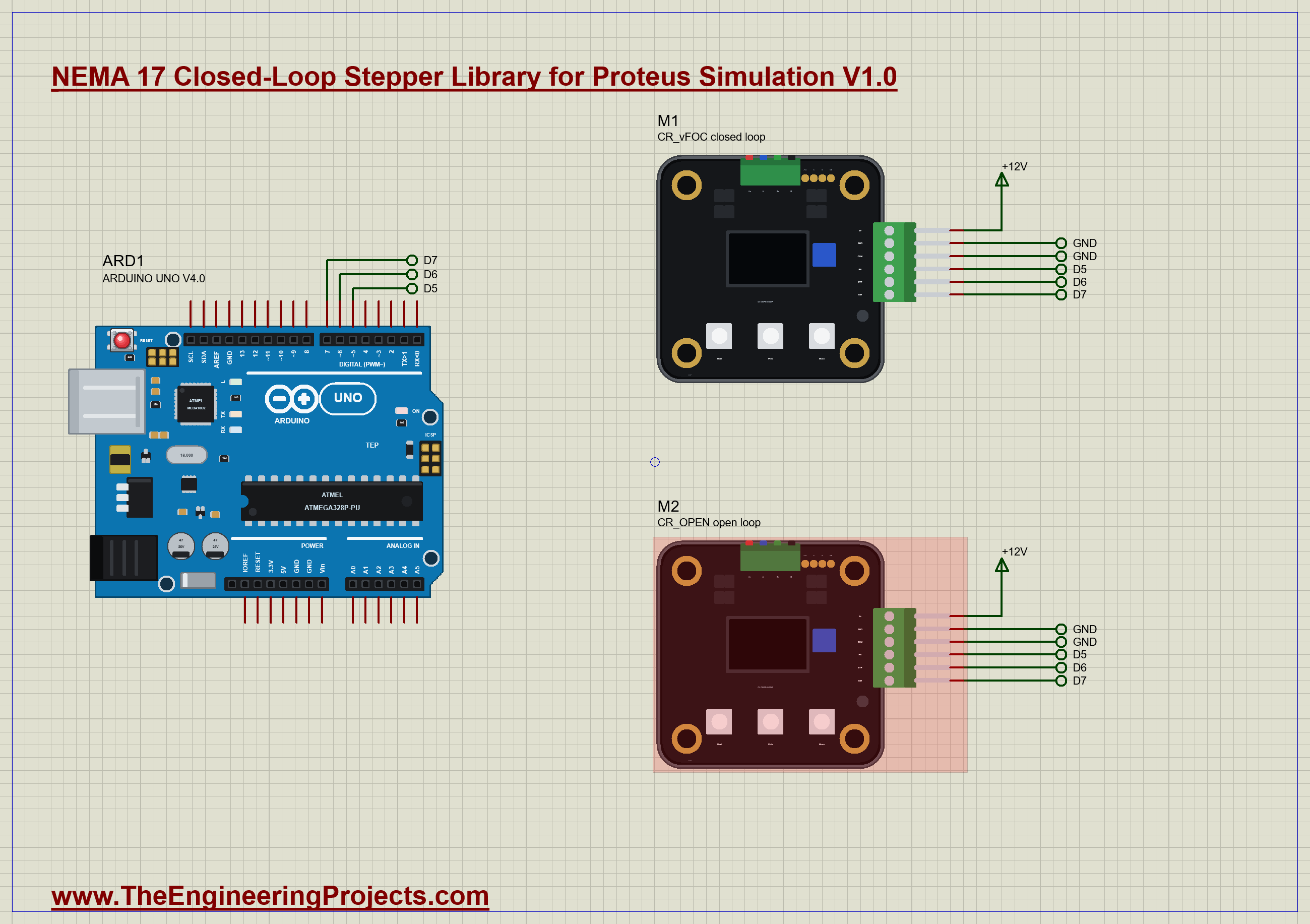
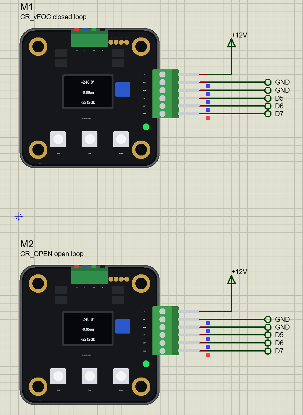
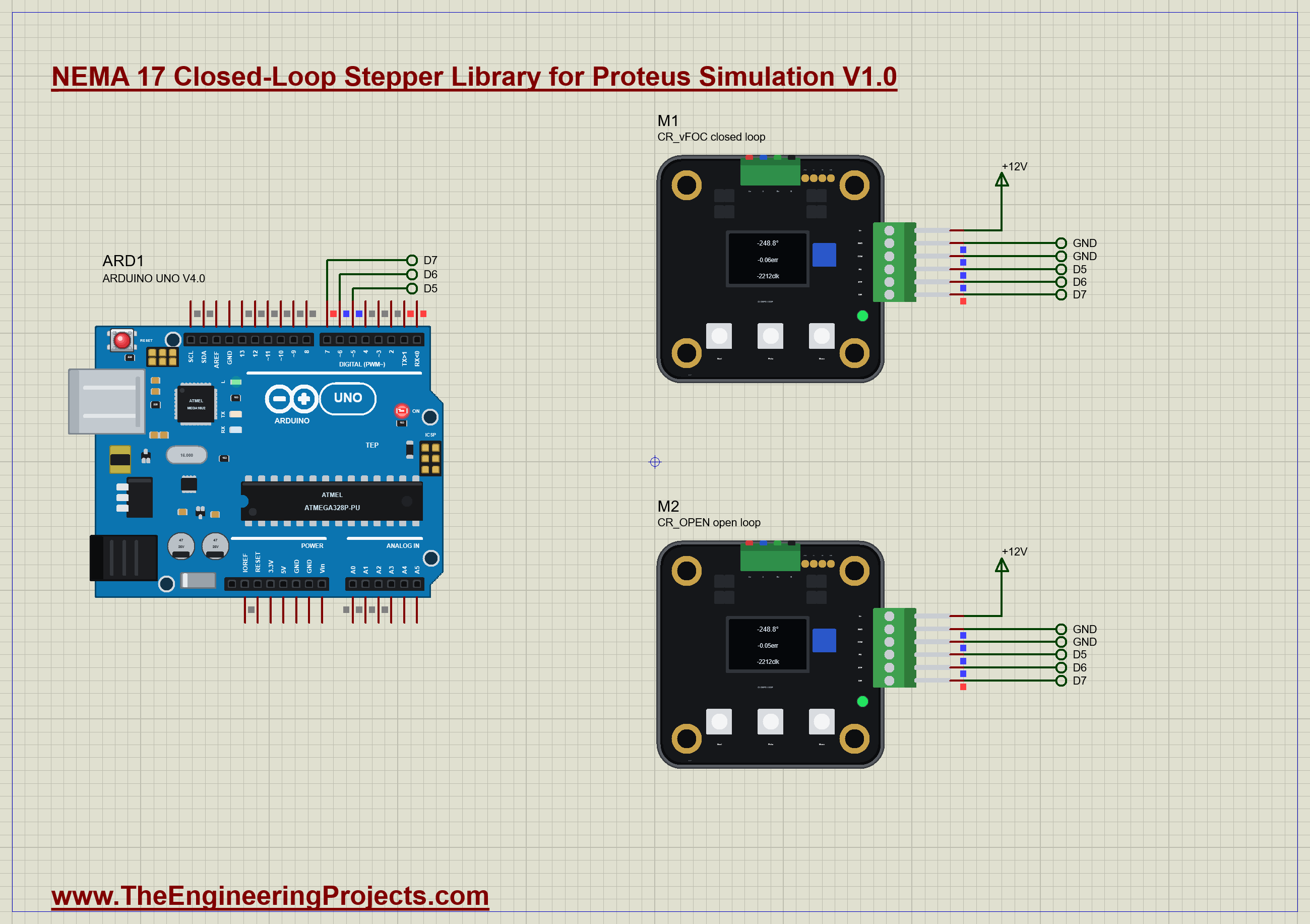
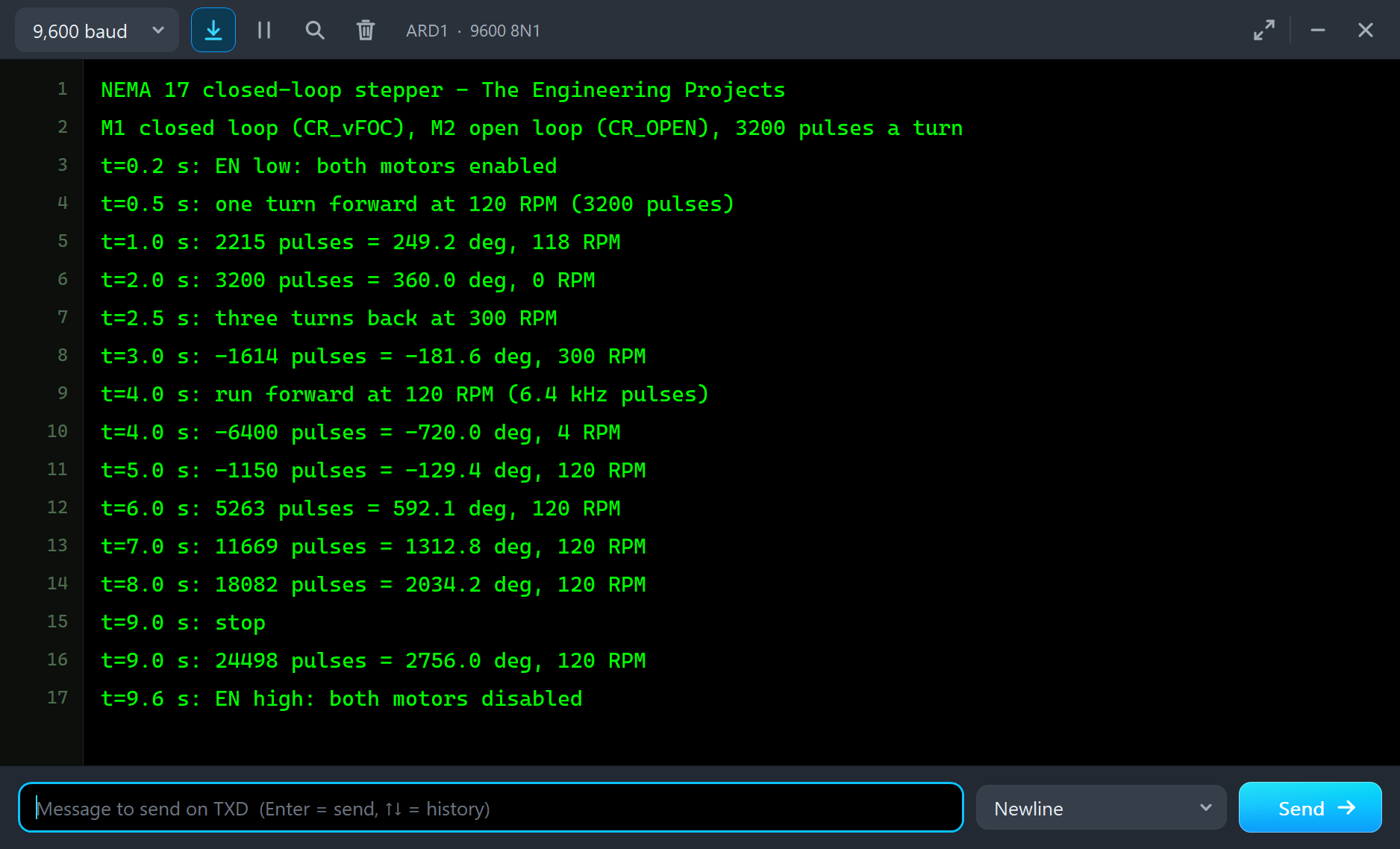
The demo has our Arduino UNO Library for Proteus V4.0 with its built-in monitor, the same window as our TEP Serial Monitor Advance for Proteus, and two of these motors. M1 runs in closed loop (MODE CR_vFOC), M2 in open loop (MODE CR_OPEN at 1200 mA). Both sit on a 12 V terminal with GND and COM on the ground, and both take the same three signals from the UNO: EN from D5, STP from D6 and DIR from D7, exactly as the real board's documentation wires it to an Arduino. Open NEMA17CL-ArduinoUnoV4.pdsprj.
The Sketch
The pulses come from Timer1, set to interrupt once for every pulse. The interrupt sends one pulse and counts it, while a move still has pulses left:
ISR(TIMER1_COMPA_vect) {
  if (toGo == 0) return;
  digitalWrite(STP_PIN, HIGH);
  pos += dirStep;
  if (toGo > 0) --toGo;
  digitalWrite(STP_PIN, LOW);
}
The pulse rate sets Timer1's compare value; at a 2 MHz timer clock, 6400 pulses a second, 120 RPM at 16 microsteps, is a compare value of 311:
noInterrupts(); OCR1A = (uint16_t)(2000000.0 / f) - 1; if (TCNT1 > OCR1A) TCNT1 = 0; interrupts();Every millisecond the loop ramps the rate towards its target, and a move starts to slow down early enough to stop on its last pulse:
if (left > 0) { const float vStop = sqrt(2.0 * accel * left); if (vStop < target) target = vStop; }The program enables both motors at 0.2 s, turns them one turn forward at 120 RPM at 0.5 s, three turns back at 300 RPM at 2.5 s, runs forward at 120 RPM from 4 s to 9 s, and sets EN high at 9.6 s. Afterwards you can type m 1600, v 200, s or e 0 in the monitor.
Closed-Loop Stepper Simulation Results
Open the project and press Run. The program runs about 10 simulated seconds; with both pop-ups open and the pictures being taken it took about four minutes on our PC. Click each motor to open its pop-up. Every number below comes from one simulation run, the demo exactly as it ships, with two clicks on the load chips of both pop-ups.
One Turn at 120 RPM
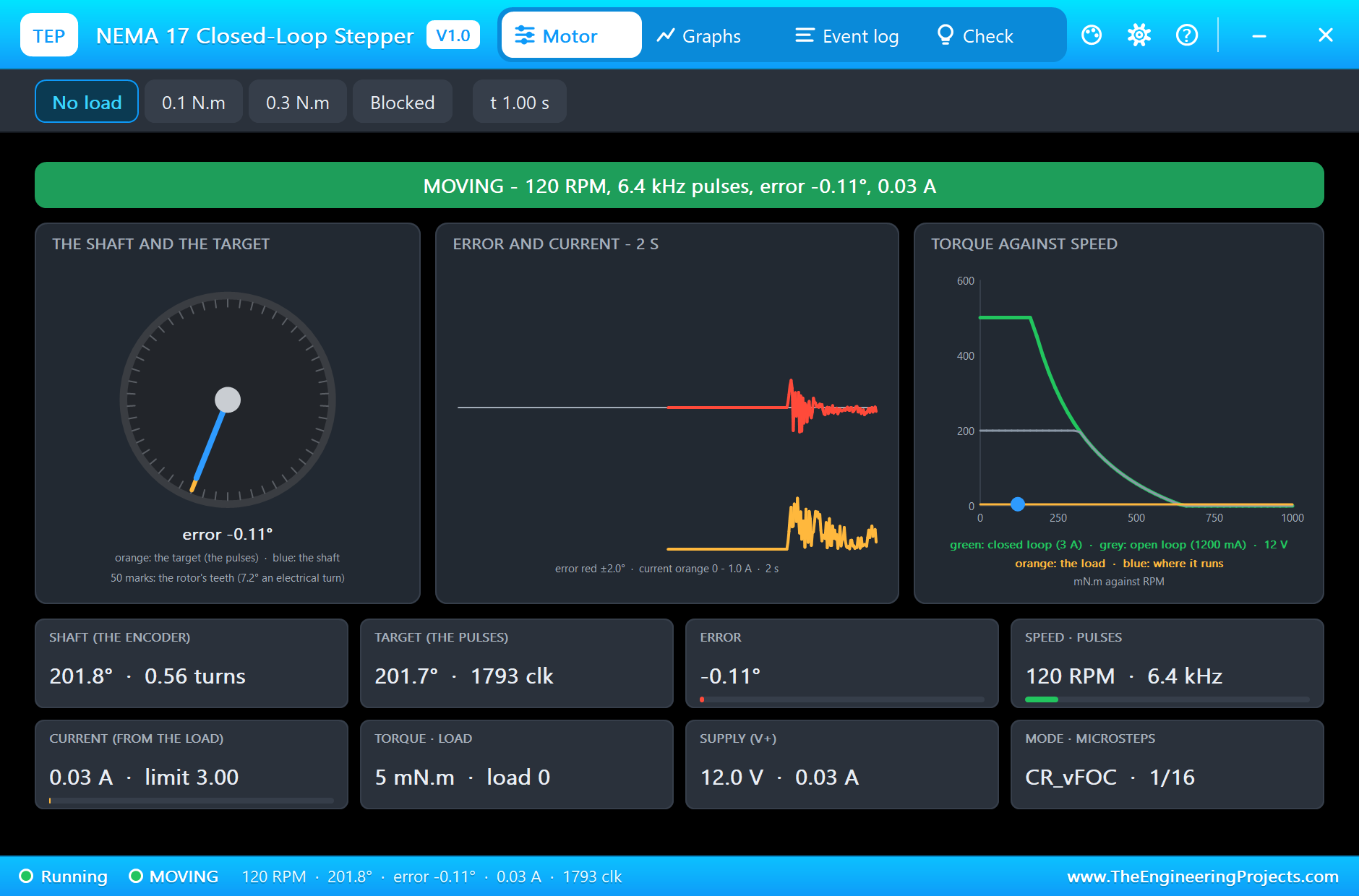
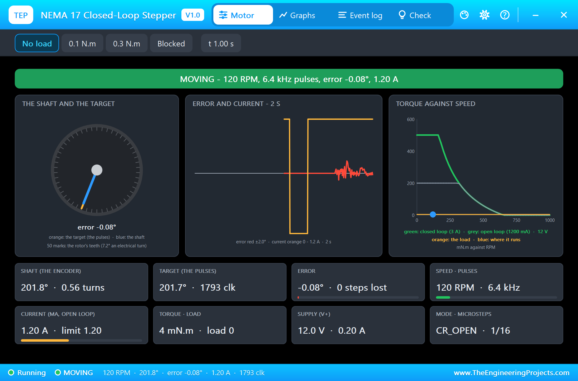
At 0.5 s the UNO sends 3200 pulses with a ramp up to 120 RPM. At 1 s M1 is MOVING at 120 RPM, 0.11 degrees off its target, on just 0.03 A: with no load the closed loop needs almost no current. M2, the open-loop motor, moves the same way, 120 RPM and 0.08 degrees off, but on its full 1.2 A all the time.
Three Turns Back at 300 RPM
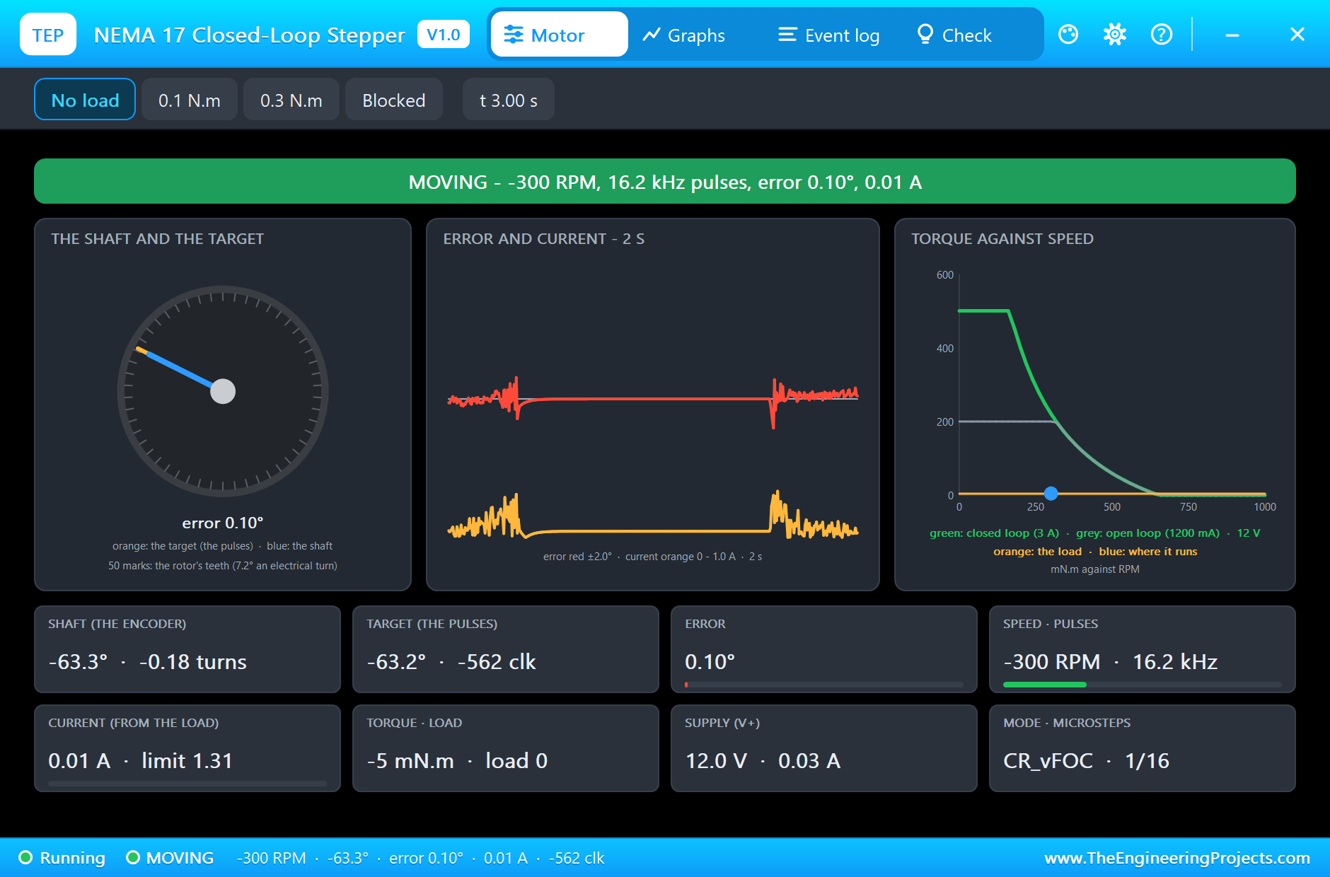
At 2.5 s both motors run three turns back at 300 RPM, 16 000 pulses a second. At 3 s M1 turns at 300 RPM, 0.10 degrees off its target. The torque card shows why the voltage matters: at 12 V the torque the driver can give falls quickly above about 170 RPM, because the motor's back-EMF eats into the supply. Both motors end the move exactly on the target, two turns back from where they started.
A 0.3 N.m Load
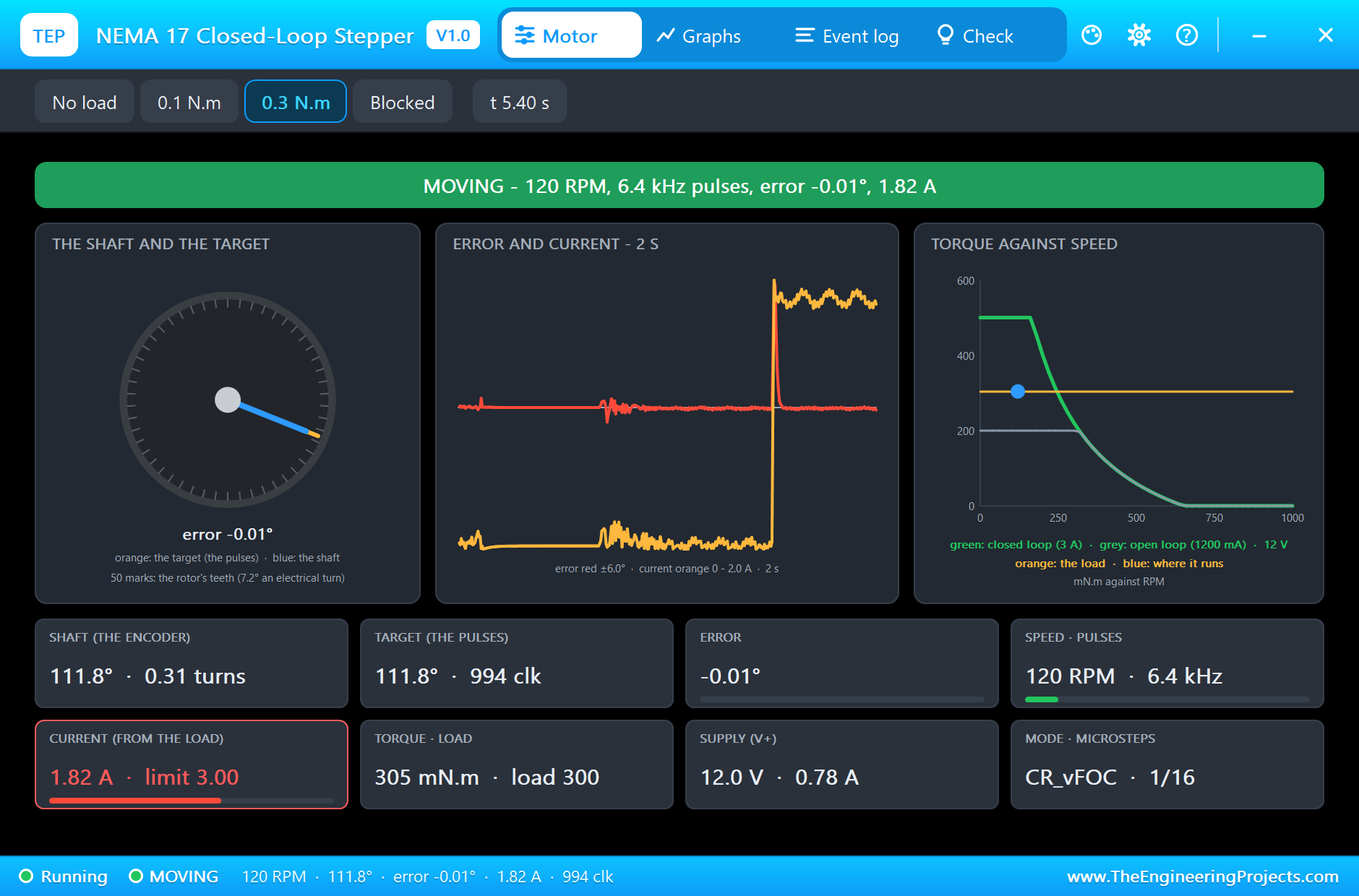
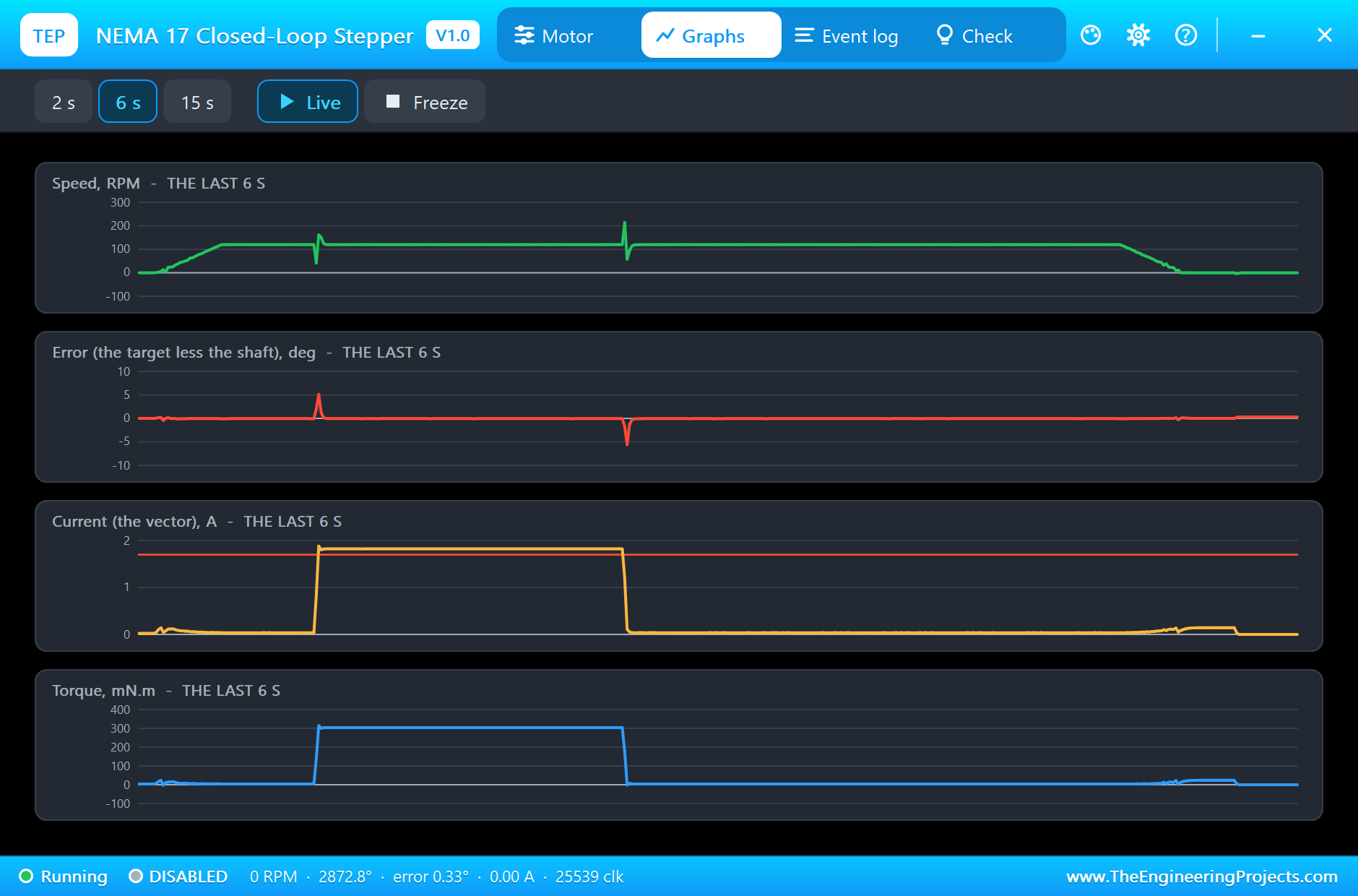
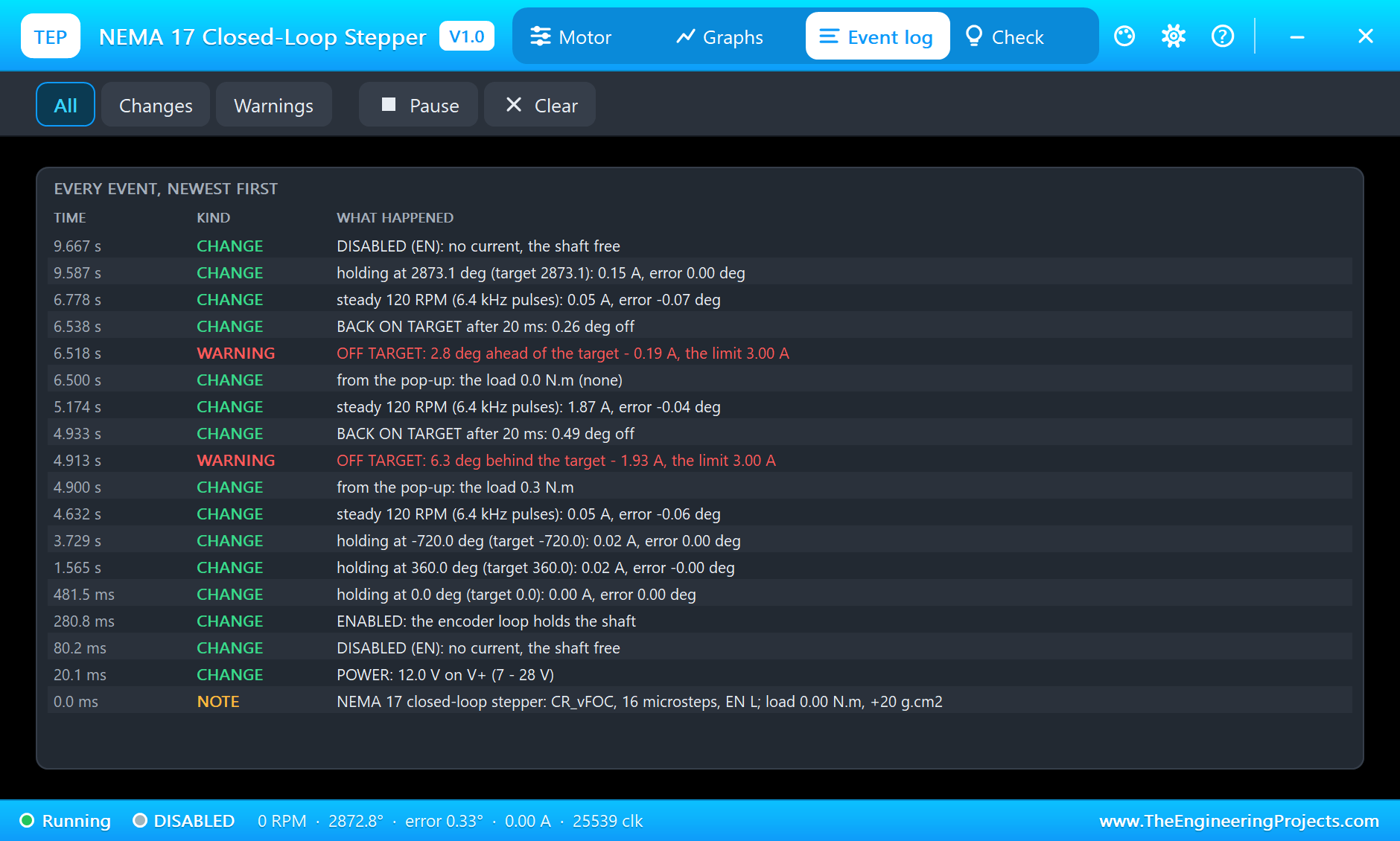
From 4 s both motors run forward at 120 RPM. At 4.9 s we clicked the 0.3 N.m chip on both pop-ups. For M1 the error jumps for an instant: the Event log notes OFF TARGET, 6.3 degrees behind, and 20 ms later BACK ON TARGET, while the current climbs. At 5.4 s it is MOVING at 120 RPM with 1.82 A and 305 mN.m, 0.01 degrees from the target. The working point on the torque card sits on the load line, well under the closed-loop curve.
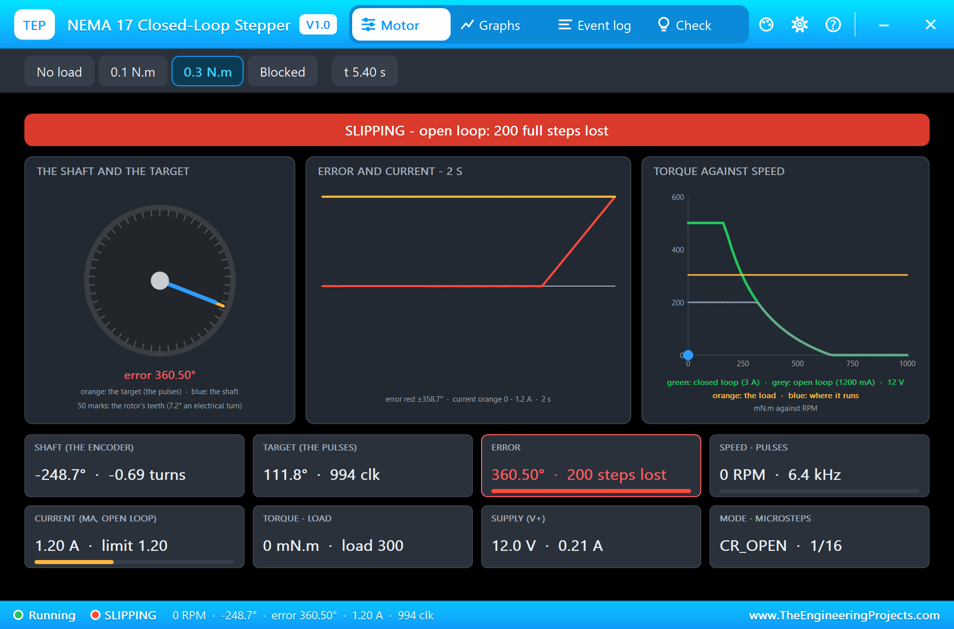
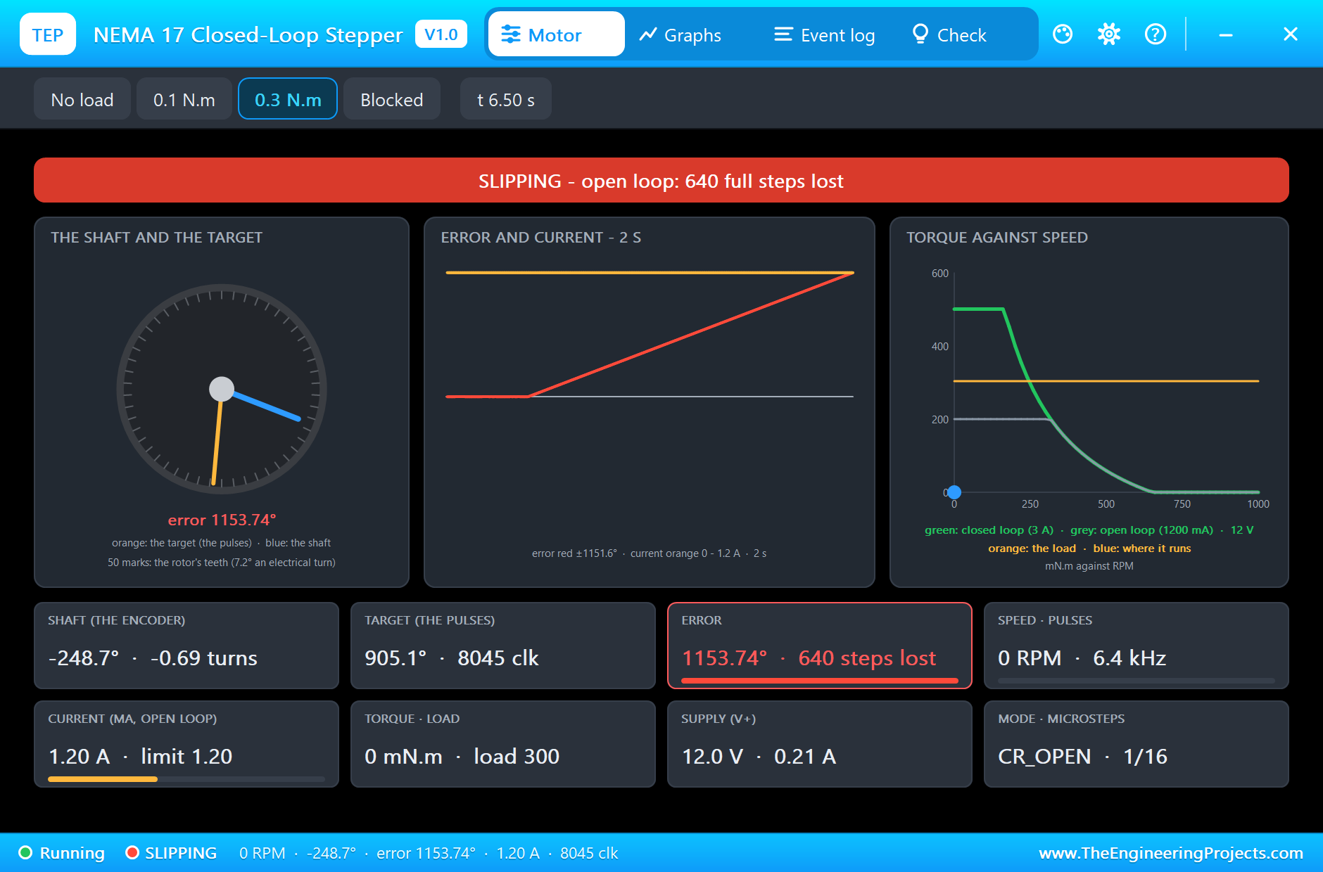
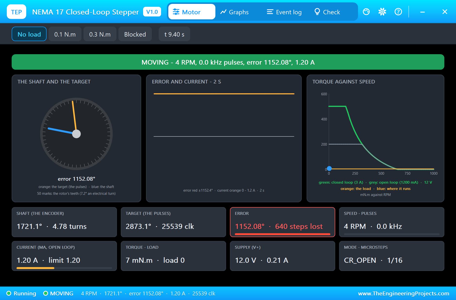
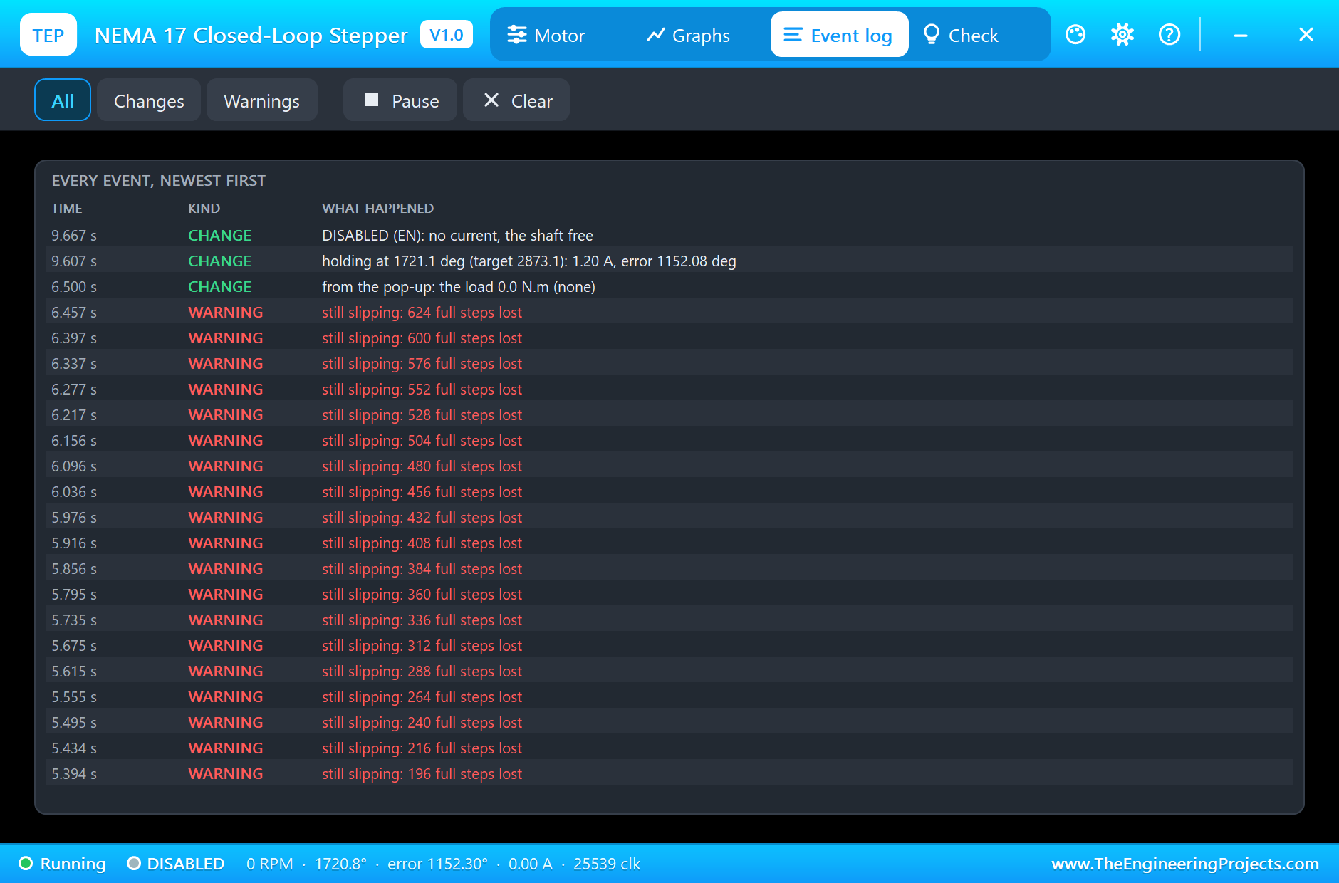
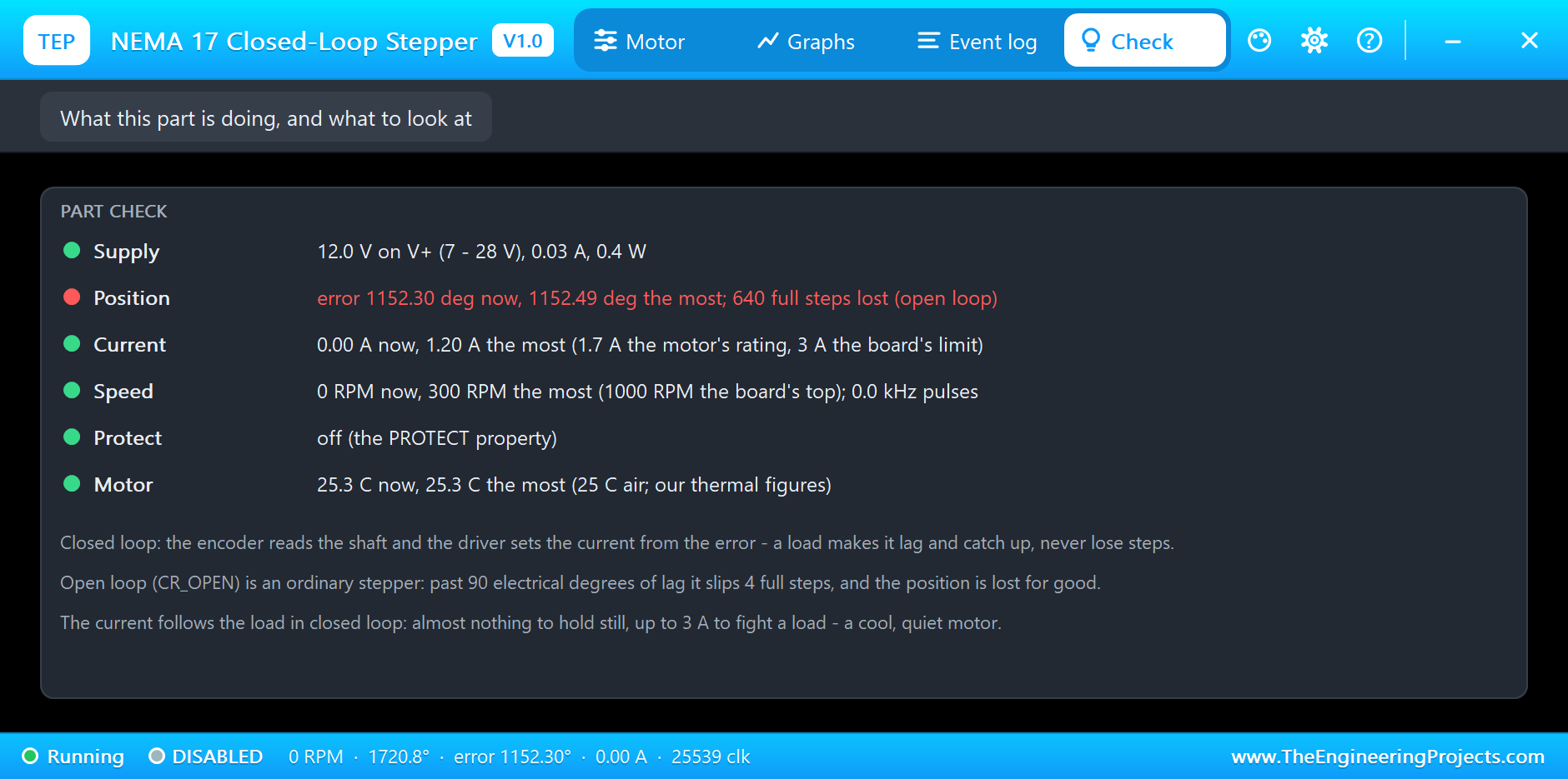
M2 has only 1.2 A, enough for about 0.2 N.m. Its banner turns red, SLIPPING, and the shaft stops while the field keeps turning: at 5.4 s it is 360.5 degrees behind, 200 full steps lost, and at 6.5 s 1153.7 degrees, 640 steps. The Event log counts every slip.
The Load Off
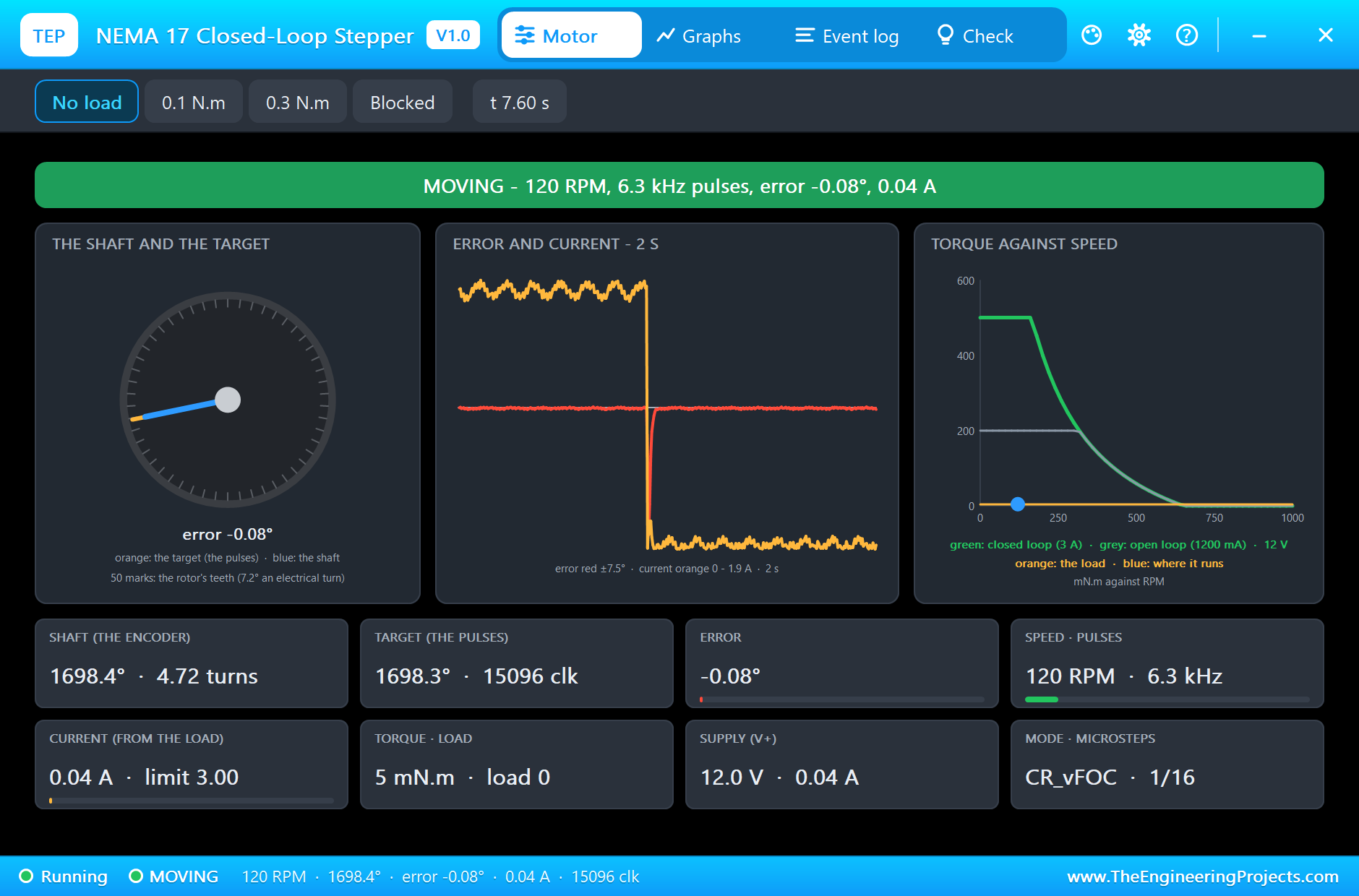
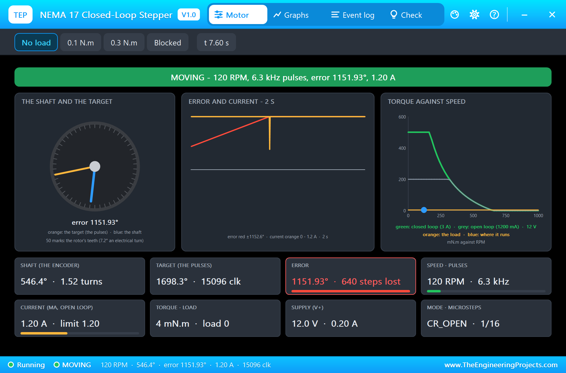
At 6.5 s we clicked No load on both. M1 hardly notices: at 7.6 s it runs on its target, 0.08 degrees off, back to 0.04 A. M2 picks up the field again and runs, MOVING at 120 RPM, but the steps it lost are gone for good: it is 1151.9 degrees behind, 640 full steps, and nothing in an open-loop system will ever tell the controller.
Stopped
At 9 s the UNO ramps down and stops. Both motors have received exactly the same pulses. M1 holds at 2873.0 degrees, 0.11 degrees from its target; M2 settles at 1721.1 degrees (its banner still shows the last 4 RPM of the stop), 1152.1 degrees short. At 9.6 s EN goes high and both are free.
The Graphs, the Event Logs and the Check Page
The Graphs page plots the speed, the error, the current and the torque over the last 2, 6 or 15 simulated seconds; for M1 the load shows as a step in the current and a short spike in the error. M1's Event log keeps the moves, the steady speeds with their current, the load, a short OFF TARGET and BACK ON TARGET; M2's keeps every SLIP and the steps lost, and its Check page ends the run in red.
Try It Yourself
- Set PROTECT to Enable on M1 and click Blocked: after half a second the motor switches off and the OLED shows "Wrong Protect".
- Raise M2's MA to 2000 mA: it now carries 0.3 N.m too, close to its limit, but it holds 2 A all the time and heats up.
- Type
v 600and click 0.1 N.m: on 12 V the back-EMF leaves only about 0.1 A, and M1 falls behind; change the supply to 24 V and it follows. - Set MSTEP to 32 on both motors and in the sketch: twice the pulses for the same speed.
- Click 0.1 N.m: both motors carry it; the open loop only fails when the load passes its holding torque.
Ideas to Extend the Demo
- Read a button or a sensor and stop on it: a homing move.
- Add a second axis with its own STP and DIR: two motors moving together, as on a plotter.
- Ramp the speed up until M2 stalls: find its pull-out speed against M1's.
Your Own Sketches
The demo sketch is in the zip file, and you can change it in the Arduino IDE. New to Arduino? Start with our Arduino Tutorial for Beginners. Export the compiled binary, and set the UNO's PROGRAM property to the new file. Our guide on How to get the HEX file from Arduino shows you where the file ends up.
Things to Know Before Using a Real Closed-Loop Stepper
- Calibrate first: the real board learns its encoder with the motor unloaded (CAL in its menu); swap two motor wires if it jitters.
- Choose the voltage for the speed: the current limit sets the torque at low speed, the supply voltage at high speed.
- PROTECT is off by default: without it a blocked motor keeps pushing up to 3 A.
- Wire COM: the opto inputs need COM on the controller's ground, or they do not see the pulses.
Troubleshooting
- It does not move: EN is not active (EN L needs EN low), no pulses reach STP, or V+ is under 7 V.
- OFF TARGET: the load needs more than the current limit gives at this speed; lower the load or the speed, or raise V+.
- SLIPPING: an open-loop motor's load is over its holding torque; use closed loop or raise MA.
- PROTECT: the shaft was blocked; free it, then set EN off and on.
- The part is not simulated:
TEPNEMA17CL.DLLis missing from MODELS and from the project folder.
Limitations of the Simulation
- The closed loop is a PID tuned by us at 80 Hz; the real firmware's loop and its calibration are not copied.
- The coils' current ripple, the encoder's own error, the UART mode and the menu keys are not modelled.
- The motor's data are those of the common 17HS4401 class; the thermal figures are our estimates.
- Arduino is a name of Arduino; this library is not made or endorsed by Arduino, Labcenter or any board or motor maker.
- Tested in Proteus 8.5 in November 2026 (the demo as shipped). Proteus 7 is not supported.
So, that was all about the NEMA 17 Closed-Loop Stepper Library for Proteus Simulation. I hope it helps you see in a simulation what an encoder does for a stepper: the same pulses, the same motor, and under the same load one keeps every step while the other loses hundreds, with a pop-up that shows the error, the current and the torque behind it. If you have any questions, ask in the comments and I will help you out. Till the next tutorial, take care and have fun!

Comments
0