


Small Transistors Library for Proteus: 2N2222A, BC547, 2N2907A, BC557


Hello friends, I hope you all are doing great. Today, I am going to share the new Small Transistors Library for Proteus. The small bipolar transistor is the workhorse of electronics: it switches relays, motors and LEDs from a microcontroller pin, amplifies weak signals, drives speakers and buffers outputs. Four parts cover most of what hobbyists and students ever need, and those are the four in this library.
Small Transistors Library for Proteus
Latest version: V1.0 (November 2026, this tutorial)
Helping Tools
- Serial Monitor Advance: a serial terminal window for the UART of your board
- Serial Monitor Expert: the serial monitor with extra debugging tools
- LCD Library for Proteus V3.0: 16x2, 20x4 and I2C LCDs to show your readings
You get the 2N2222A and BC547B NPN transistors and their PNP partners, the 2N2907A and BC557B, all in the black TO-92 body at true scale, each with its own print and its own pinout. Under the body is a proper transistor model: the two junctions, the Early effect that tilts the output curves, and high injection that lowers beta at high currents, solved the way SPICE solves it. The pop-up names the region the transistor is in, cut off, active or saturated, draws its output curves with the working point on them, and keeps track of its power and heat. The demo uses all four: an LED dimmer, a PNP high-side switch and a push-pull speaker driver.
NOTICE: Our team has put a lot of effort into these small parts: the bodies, the animation and the pop-ups are all our own design, and you get them free. Your feedback is the fuel that keeps us going, so please tell us what you think in the comments below or in the Small Transistors board of our forum. And if our free libraries help you, you can buy us a coffee. So, let's get started with the Small Transistors Library for Proteus:
What is a Bipolar Transistor?
A bipolar junction transistor, or BJT, has three layers of doped silicon and three pins: the emitter, the base and the collector. In an NPN transistor, a small current flowing into the base and out of the emitter lets a much larger current flow from the collector to the emitter. The ratio of the two is the current gain, called beta or hFE: a BC547B with 20 µA into its base can carry about 5 mA through its collector. That is the whole trick, and everything else follows from it.
A PNP transistor is the mirror image: its current flows out of the base and in at the emitter, and everything is the other way up. An NPN suits the low side of a load, between the load and ground; a PNP suits the high side, between the supply and the load. Pairs of matching NPN and PNP parts, called complementary pairs, work together in push-pull stages.
| Part | Type | Pinout | Rating | hFE |
|---|---|---|---|---|
| 2N2222A | NPN | E B C | 40 V, 600 mA, 625 mW | 100 to 300 |
| BC547B | NPN | C B E | 45 V, 100 mA, 500 mW | 200 to 450 |
| 2N2907A | PNP | E B C | 60 V, 600 mA, 625 mW | 100 to 300 |
| BC557B | PNP | C B E | 45 V, 100 mA, 500 mW | 200 to 450 |
The TO-92 Package and Its Pinouts
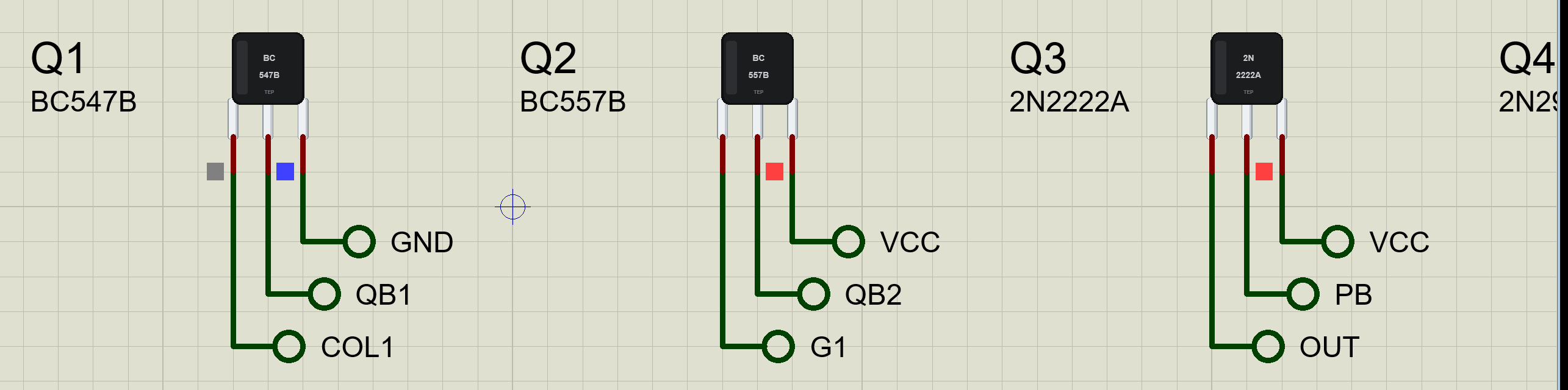
TO-92 is the small black half-cylinder you see on every hobby board: 4.6 mm wide, with three legs on a 2.54 mm pitch. Hold it with the flat face towards you and the legs down, and read the pins from left to right. Here is the catch that trips everyone up at least once: the 2N2222A and 2N2907A are E B C, but the BC547 and BC557 are C B E. The body is identical; the ends are swapped. The pop-up shows each part's pinout, and if you wire a transistor the wrong way round, it tells you.
The Three Regions
A transistor works in one of three regions. Cut off: the base-emitter junction gets less than about 0.6 V, no base current flows and the transistor is an open switch. Active: the base current controls the collector current, Ic = beta x Ib, and the collector voltage can sit anywhere in between; this is the region for amplifiers. Saturated: the base gets more current than the collector can use, the collector voltage drops to about 0.1 V and the transistor is a closed switch. A fourth, reverse active, happens when collector and emitter are swapped; it works badly, with a beta of only a few, and is almost always a wiring mistake.
Output Curves
The classic way to show a transistor is its output curves: the collector current against the collector-emitter voltage, one curve for each base current. Each curve rises steeply near zero volts, the saturation region, and then levels out into a nearly flat line, the active region, where the collector current depends on the base current and hardly at all on the voltage. The small upward slope of the flat part is the Early effect. Our pop-up draws four such curves around the transistor's present base current, and puts a dot on its working point.
Beta Is Not a Constant
A datasheet gives hFE as a range, 200 to 450 for a BC547B, because it varies from part to part, with temperature and with current. At high currents, beta falls: the base region fills with carriers and the gain drops, an effect called high injection. Our model includes it, so a 2N2222A pushing over 100 mA shows a lower beta than the same part at 5 mA. Good designs never rely on an exact beta: switches get plenty of base current, and amplifiers use feedback.
A Transistor as a Switch
To use a transistor as a switch, drive it hard into saturation. The rule of thumb is a base current of a tenth of the collector current, whatever the beta: a forced beta of 10. The base resistor is then R = (Vpin - 0.7 V) / (Ic / 10). A transistor that is only just saturated, with a forced beta near its real one, leaves a larger voltage across itself and gets warmer; the Check page marks that amber. And never connect a base straight to a pin: the base-emitter junction is a diode, and without a resistor it would draw far too much current.
Power and Heat
A transistor heats with the power it dissipates, Vce x Ic plus a little for the base. In saturation Vce is small, so a switch stays cool; in the active region, with several volts across it, the same current makes far more heat. A TO-92 can take 500 or 625 mW in free air. Our model follows the power with a thermal time constant and, if it runs past twice its rating, the transistor fails short between collector and emitter, as real ones usually do, until you fit a new one from the pop-up.
How the Model Works
The model is in the style of SPICE's Gummel-Poon transistor. Each junction follows the diode equation; the transport current flows from collector to emitter, divided by a base charge factor that includes the Early voltage and the knee current where high injection begins; and the base current is the two junction currents divided by the forward and reverse betas. At every step of the simulation, Proteus asks the model for its tangent, a small linear circuit that matches it at the present voltages, and the junction voltages are limited between steps exactly as SPICE limits them, so the exponentials can never run away. That is what makes it converge reliably in switches, amplifiers and push-pull stages alike.
Where They Are Used
The 2N2222A switches relays, solenoids, small motors and LED strips from microcontroller pins. The BC547 amplifies microphones and sensors and appears in countless simple circuits. Their PNP partners switch power on the high side and pair with them in push-pull stages, H-bridges and current mirrors. Together they are the four transistors in almost every electronics kit.
Features of the Small Transistors Library for Proteus
- The real look, at true scale: four TO-92 transistors, each with its own print and pinout, and our small TEP signature.
- A real transistor model: the junctions, the Early effect and high injection, with SPICE-style junction limiting.
- It names its region: cut off, active, saturated, or reverse when it is wired backwards.
- Live output curves: Ic against Vce at four base currents, with the working point on them.
- Power and heat: the average power, the heat on its way to failure, and a short-circuit failure past twice its rating.
- A pop-up for every transistor: the region, the curves, eight live values, graphs, an event log and a check page.
- A complete package: about 2.9 MB with the library, our Arduino UNO V4.0, our resistors, pot, LEDs, capacitor and speaker and the demo, without the source code of the model.
The Transistors in Proteus
The devices are Q2N2222ATEP, BC547BTEP, Q2N2907ATEP and BC557BTEP in TEPBJT.LIB, under Transistors, Bipolar, with the prefix Q and the model TEPBJT.DLL. Search 2N2222, 2N2907, BC547 or BC557 in Pick Devices. Each has three pins named E, B and C, in the order of the real part.
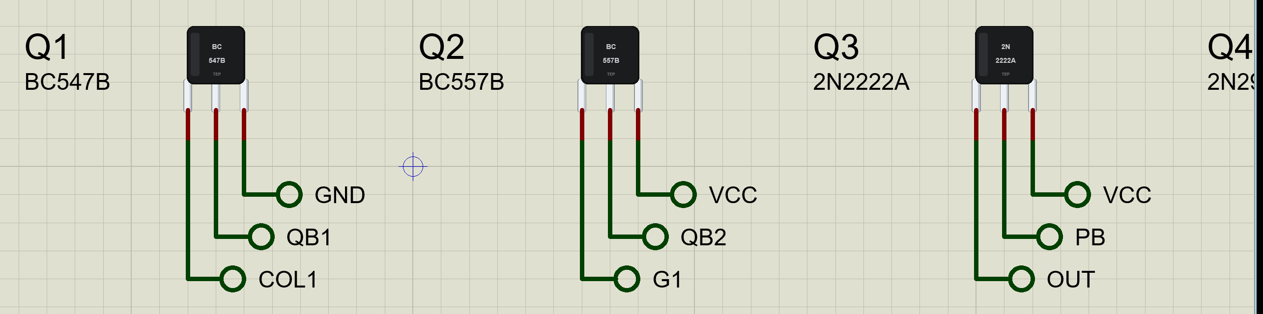
There are no properties to set: each part carries its own parameters, taken from its datasheet and its published SPICE model.
Download Small Transistors Library for Proteus
Click the button below to download Small-Transistors-Library-for-Proteus-v1.0.zip (about 2.9 MB, without the source code of the models):
Small Transistors Library for Proteus V1.0- README.txt: installation, the demo, the pinouts, troubleshooting and the limits.
- Proteus Library Files:
TEPBJT.LIB, our resistor, pot, LED, capacitor and speaker libraries, and ourArduinoV4TEP.LIB. - Proteus Model Files:
TEPBJT.DLL, the DLLs of those parts andTEPARDUINO.DLL. - Arduino Code: the demo sketch.
- Proteus Simulation: the demo project, its HEX file and copies of the DLLs.
No Proteus yet? Read How to Download and Install Proteus 7 and 8. New to libraries? Follow How to Install a New Library in Proteus.
How to Install Small Transistors Library for Proteus
- Close Proteus and extract the whole zip file, for example to your Desktop.
- Copy the files from Proteus Library Files into the LIBRARY folder of Proteus.
- Copy the files from Proteus Model Files into the MODELS folder.
- Delete
TEPBJT.IDXfrom the LIBRARY folder if it is there. - Start Proteus, press P and search for 2N2222.
Demo: Three Jobs for Four Transistors
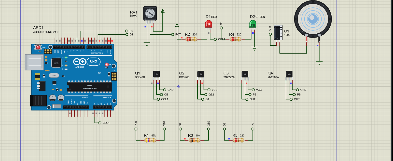
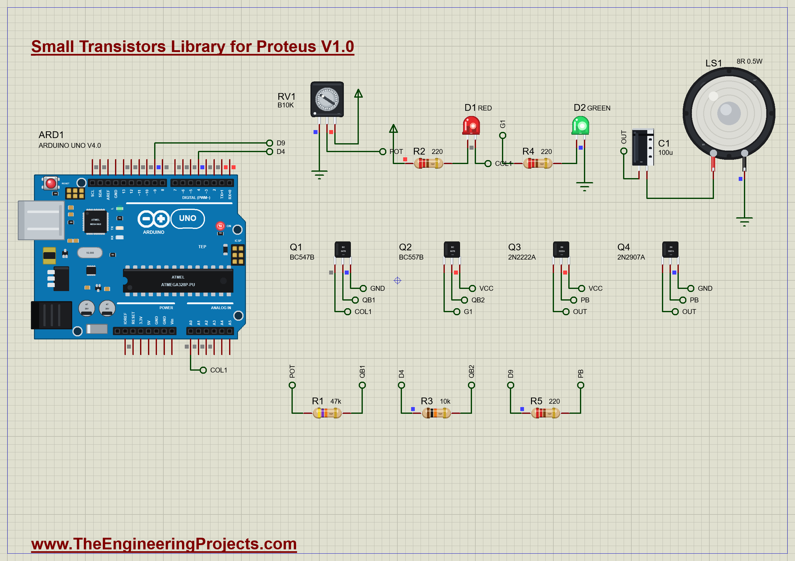
Q1, a BC547B, is an LED dimmer: the knob RV1 feeds its base through R1, 47k, and the red LED with R2 sits in its collector, which also goes to A0. Q2, a BC557B, is a high-side switch: its emitter is on the 5 V rail, and D4 pulls its base low through R3, 10k, to light the green LED. Q3, a 2N2222A, and Q4, a 2N2907A, form a push-pull buffer: D9 drives both bases through R5, and their joined emitters drive our speaker through a 100 µF capacitor. Open Small-Transistors-ArduinoUnoV4.pdsprj. It runs on our Arduino UNO Library for Proteus V4.0, with its built-in monitor, the same window as our TEP Serial Monitor Advance for Proteus. The resistors are from our Resistor Library for Proteus, the knob from our Potentiometer Library for Proteus and the speaker from our Mini Speaker Library for Proteus.
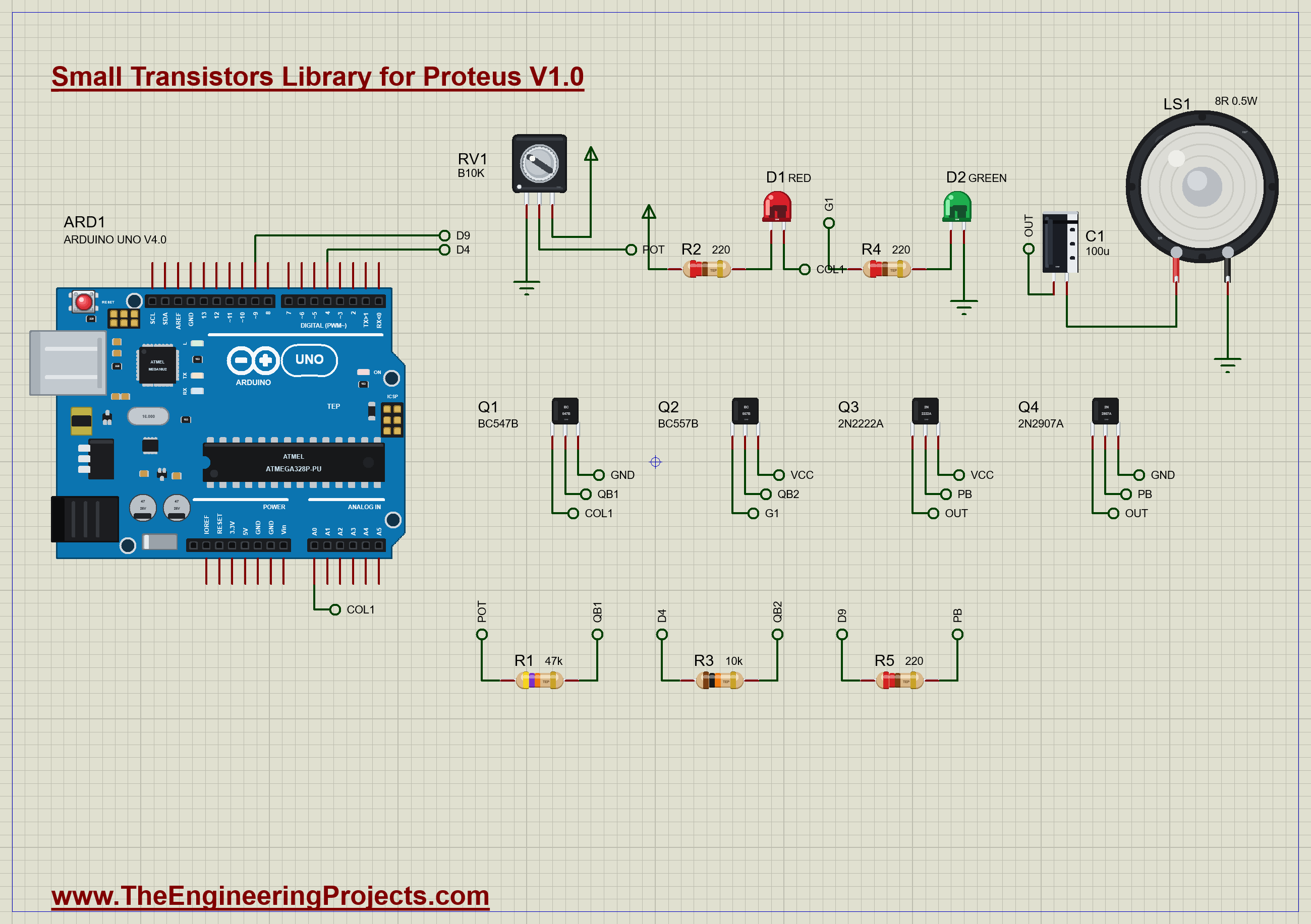
| Part | Connection | Job |
|---|---|---|
| Q1 BC547B | B via R1 from RV1, C via R2 and the red LED to +5V | an LED dimmer |
| Q2 BC557B | E +5V, B via R3 from D4, C via R4 to the green LED | a high-side switch |
| Q3 2N2222A | C +5V, B via R5 from D9, E to OUT | the push half |
| Q4 2N2907A | C GND, B via R5 from D9, E to OUT | the pull half |
| C1, LS1 | OUT through 100 µF to the speaker | the sound |
The Sketch
Q2 is a PNP on the high side, so the sketch switches it on with a LOW and off with a HIGH, blinking the green LED every second:
digitalWrite(SWITCH_PIN, greenOn ? LOW : HIGH);Every four seconds, the push-pull pair plays a short arpeggio on the speaker. The pin's square wave goes to both bases; Q3 sources current on the high half and Q4 sinks it on the low half:
void playArpeggio() {
  for (byte k = 0; k < 4; k++) {
    tone(SOUND_PIN, NOTES[k], 150);
    delay(170);
  }
}
Q1 needs no code at all: the knob drives it directly. The sketch only reads its collector voltage on A0 and prints it every second.
Run the Demo
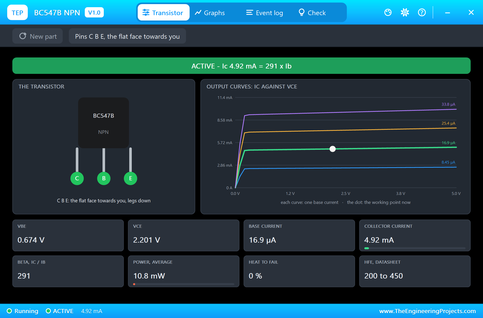
Press Run. With RV1 at 30 %, Q1 is in the active region: 16.9 µA into its base, 4.92 mA through its collector, a beta of 291, right inside the BC547B's 200 to 450. Its collector sits at 2.20 V and the red LED is half lit. On the output curves, the dot sits on the flat part of the 16.9 µA curve:
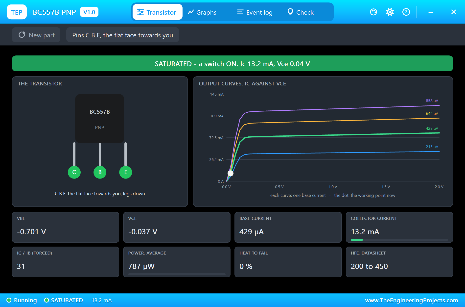
Meanwhile Q2, the BC557B, switches the green LED. With D4 LOW, it is saturated: 0.43 mA into its base, 13.2 mA through its collector and only 0.04 V across it, a closed switch. Its forced beta of 31 is low enough to keep it hard on:
Here is the complete circuit, truly running:
The Push-Pull Pair
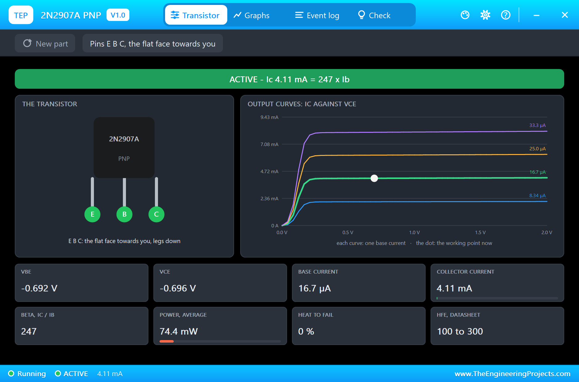
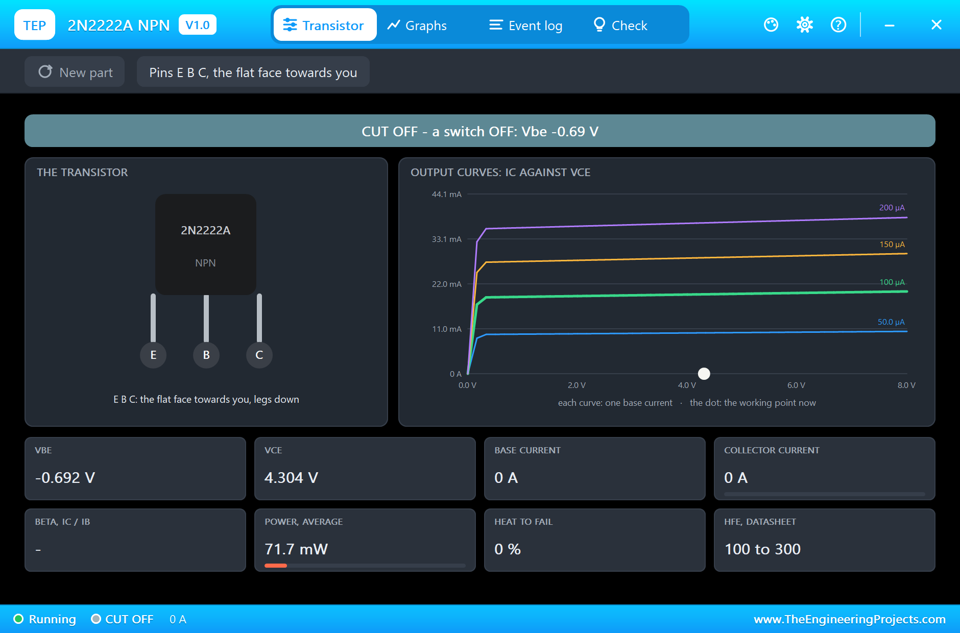
When the arpeggio plays, Q3 and Q4 take turns. We paused in the middle of a note: Q4, the 2N2907A, was just taking over, 4.1 mA and rising, while Q3 sat cut off, its base held 0.69 V below its emitter by Q4's own base-emitter drop. Half a cycle later they swap. Each one averages about 72 mW, well inside its 625 mW. In another run we caught Q3 pushing 136 mA, with a beta of 138: high injection pulling the gain down at that current, just as on a real 2N2222A:
Through Every Region
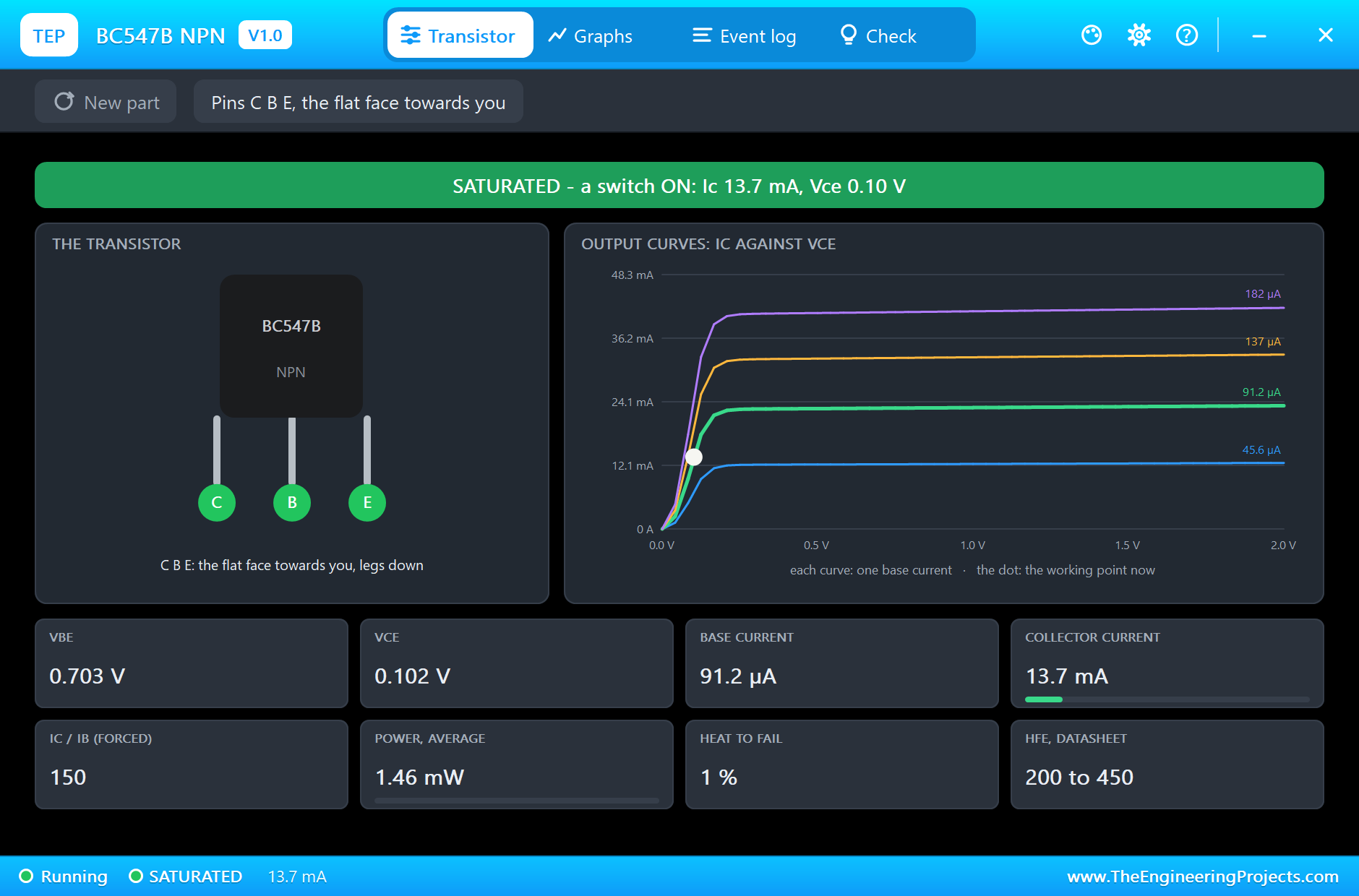
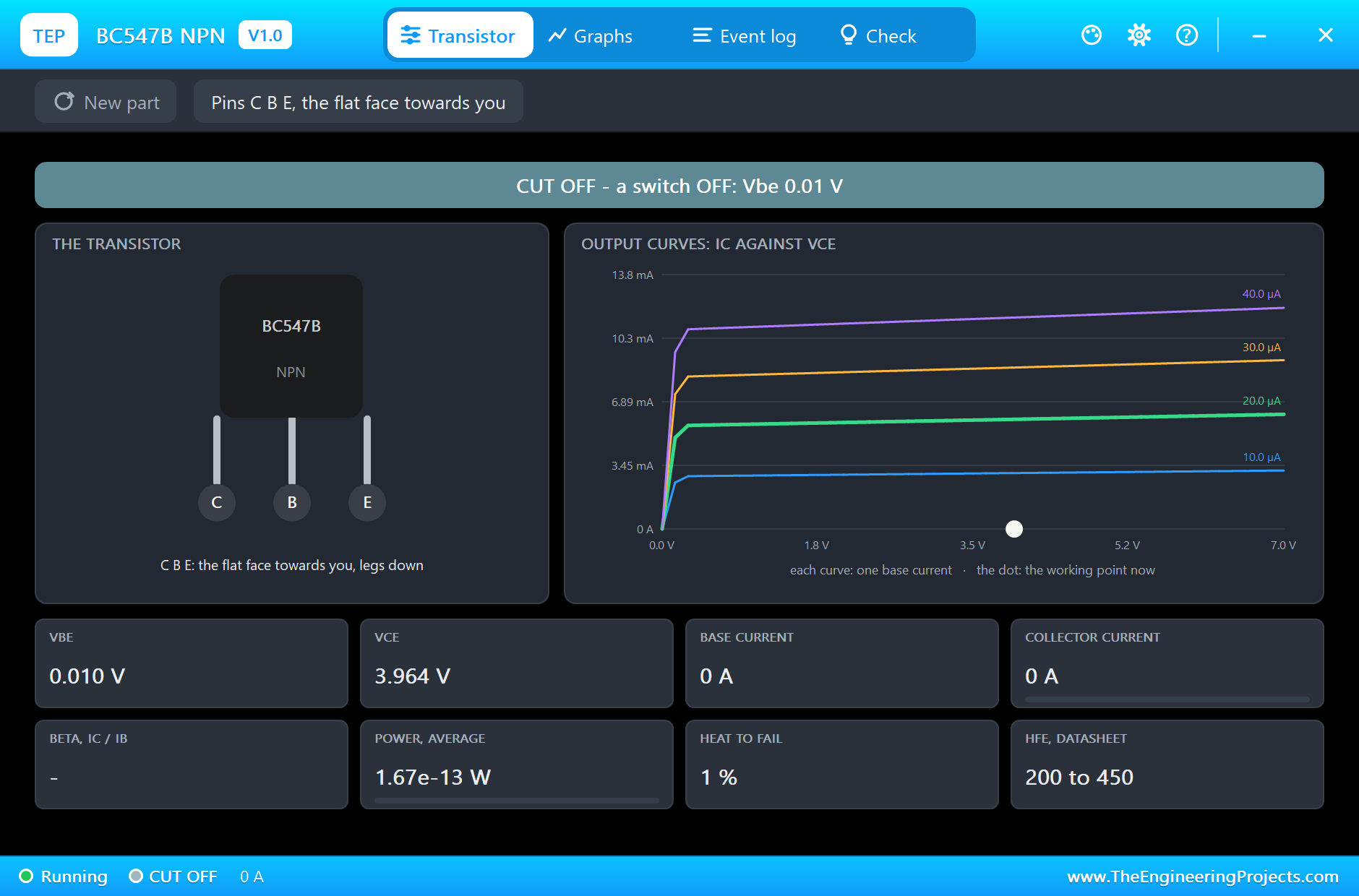
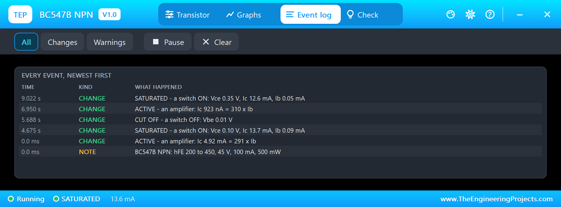
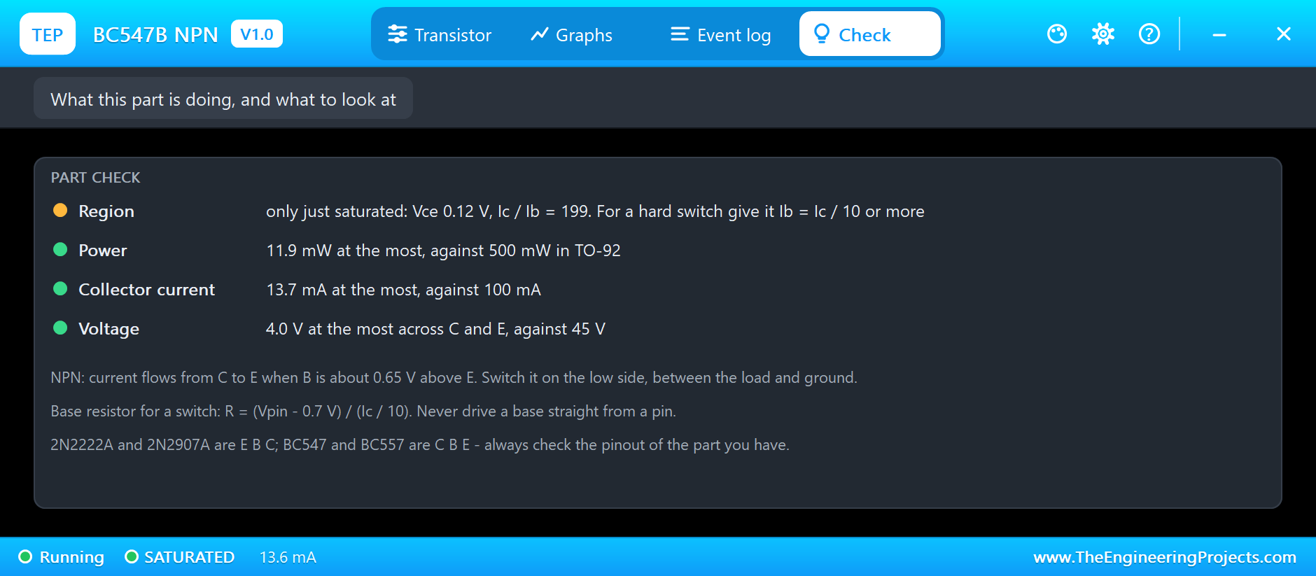
Now turn RV1 all the way up with the 100 % chip on its pop-up. Q1 saturates: 91 µA in, 13.7 mA through, 0.10 V across. Its forced beta is 150, so it is only just saturated, and the Check page says so in amber. Turn RV1 to 0 % and Q1 is cut off: no base current, no collector current, the collector up at 3.96 V and the red LED dark:
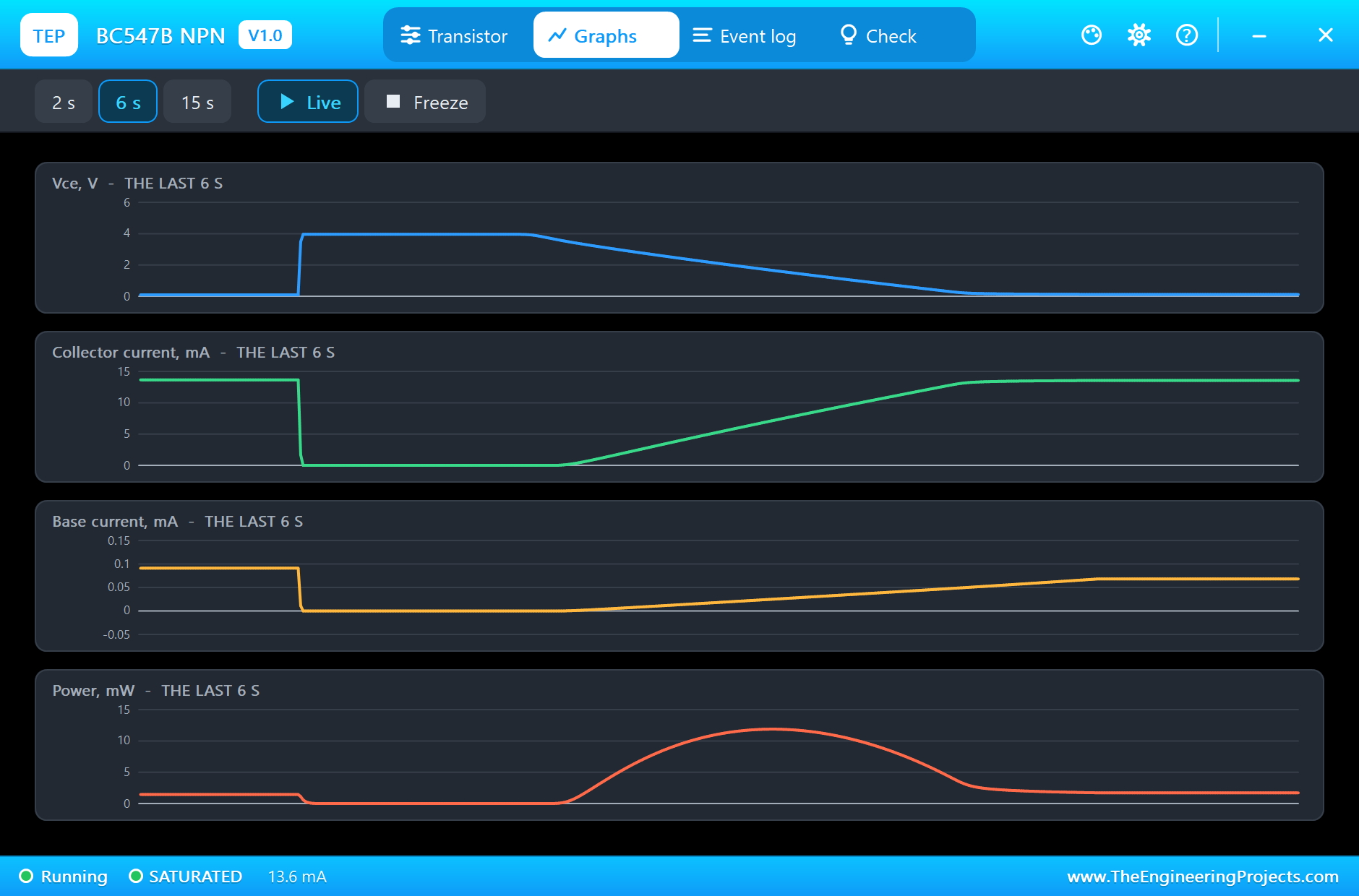
Then we let RV1 sweep. The Graphs page shows Q1 travelling through all three regions: Vce falling from 4 V to 0.1 V as the base current rises, and the collector current climbing and then levelling off at saturation:
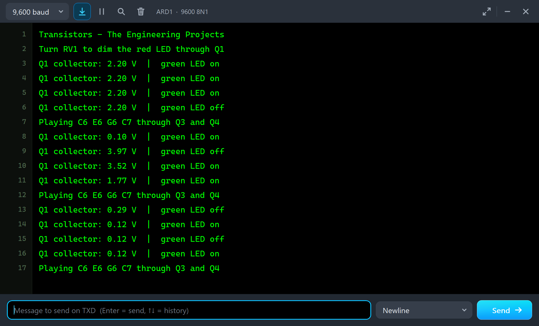
The Event log names every region change, and the monitor shows the collector voltage falling as the LED brightens:
The Check Pages
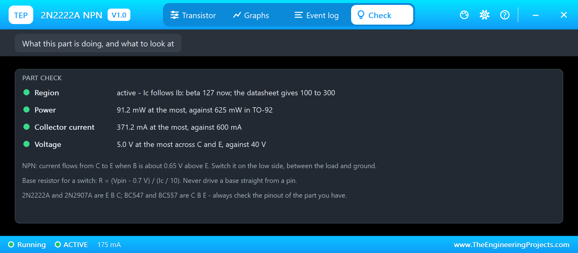
The Check page judges the region, the power against the TO-92 rating, the collector current and the voltage. For Q1 at full knob it marks the saturation amber with the advice to give it more base current; for the 2N2222A it shows the push-pull duty well within its ratings:
Try It Yourself
- Swap Q1 for a 2N2222A, and remember its pins are E B C.
- Lower R1 to 10k, and see Q1 saturate harder at full knob, with a forced beta near 30.
- Raise R3 to 100k, and watch Q2 slip out of saturation into the active region.
- Replace the push-pull with Q3 alone, and hear how the speaker only gets half the waveform.
- Wire a transistor backwards, and read REVERSE on its pop-up.
Ideas to Extend the Demo
- Switch a relay with the 2N2222A and a flyback diode.
- Build a two-transistor astable that flashes two LEDs.
- Make a constant-current LED driver with a BC547 and a resistor.
- Build an H-bridge from two NPN and two PNP transistors for a small motor.
Your Own Sketches
The demo sketch is in the zip file, and you can change it in the Arduino IDE. New to Arduino? Start with our Arduino Tutorial for Beginners. Export the compiled binary, and set the UNO's PROGRAM property to the new file. Our guide on How to get the HEX file from Arduino shows you where the file ends up.
Things to Know Before Using Real Transistors
- Check the pinout: E B C or C B E, the same body, opposite ends.
- Always use a base resistor: never a pin straight to a base.
- Switch hard: Ib = Ic / 10 keeps a switch saturated and cool.
- Mind the power: 500 to 625 mW for TO-92, less in a hot box.
- Add a flyback diode: across any coil you switch, a relay or a motor.
Troubleshooting
- REVERSE on the pop-up: collector and emitter are swapped; check the pinout.
- It never turns off: the base still gets current; a PNP's base must go up to its emitter voltage.
- Only just saturated: give it more base current with a smaller base resistor.
- FAILED: it ran past twice its power rating; find out why, then fit a new part.
- The part is not simulated:
TEPBJT.DLLis missing from MODELS and from the project folder.
Limitations of the Simulation
- The junction capacitances and switching times are left out: switching is instant.
- Vbe and beta do not drift with temperature.
- Breakdown is not modelled; the Check page warns past the voltage rating.
- Arduino is a name of Arduino; this library is not made or endorsed by Arduino or Labcenter.
- Tested in Proteus 8.5 in November 2026 (the demo as shipped). Proteus 7 is not supported.
So, that was all about the Small Transistors Library for Proteus. I hope it helps you understand what a transistor is really doing in your circuit, and build switches, amplifiers and drivers with confidence. If you have any questions, ask in the comments and I will help you out. Till the next tutorial, take care and have fun!

Comments
0