


RGB LED Library for Proteus: Real Colour Mixing on Your Sheet


Hello friends, I hope you all are doing great. Today, I am going to share the new RGB LED Library for Proteus. An ordinary LED has one colour. Look closely at any screen, though, and you will see that every colour you have ever seen on it is built from just three: red, green and blue. An RGB LED puts those three in one small dome, so that a single part can show nearly any colour you ask for.
RGB LED Library for Proteus
Latest version: V1.0 (November 2026, this tutorial)
Helping Tools
- Serial Monitor Advance: a serial terminal window for the UART of your board
- Serial Monitor Expert: the serial monitor with extra debugging tools
- LCD Library for Proteus V3.0: 16x2, 20x4 and I2C LCDs to show your readings
Our part is the common four-legged 5 mm LED, at true scale, with a milky dome. And here is the part we are proud of: the colour really mixes on your sheet. Feed it red and green and the dome turns yellow, right there in the Proteus workspace. For the demo, an Arduino fades it round the whole colour wheel, and takes any colour you type in the monitor.
NOTICE: Our team has put a lot of effort into these small parts: the bodies, the animation and the pop-ups are all our own design, and you get them free. Your feedback is the fuel that keeps us going, so please tell us what you think in the comments below or in the RGB LED board of our forum. And if our free libraries help you, you can buy us a coffee. So, let's get started with the RGB LED Library for Proteus:
What is an RGB LED?
An RGB LED is really three LEDs in one package: a red die, a green die and a blue die, sitting side by side under one dome. The lens is usually milky, to scatter the light so that your eye sees one mixed colour, and not three separate dots. Each die has its own leg, and one extra leg is shared by all three. That is why an RGB LED has four legs.
Mixing light works differently from mixing paint. Paint takes colours away, so mixing them all gives a dark mud. Light adds colours, so mixing all three gives white. This is called additive mixing, and it is how every TV, phone and computer screen works. Each pixel is three tiny lights, side by side.
| Feature | The real part | In the library |
|---|---|---|
| Dome | 5 mm, milky | 210 thou, true scale |
| Legs | four, 1.27 mm apart | R, C, G, B, 50 thou apart |
| Red forward voltage | about 2 V | 2.0 V, a property |
| Green and blue | about 3 V | 3.0 and 3.1 V, properties |
| Current | 20 mA, 30 mA at most | the same, for each colour |
Common Cathode or Common Anode?
Inside the dome, the three LEDs have to share a leg, and there are two ways to do it. In a common cathode part, the three cathodes are joined, so the long leg goes to GND, and a pin going HIGH lights its colour. In a common anode part, the three anodes are joined, so the long leg goes to +5V, and a pin going LOW lights its colour. So the logic is upside down. Our library has both, and the demo uses the common cathode one.
| Type | The long leg goes to | A colour lights when its pin is | PWM of 0 means |
|---|---|---|---|
| Common cathode | GND | HIGH | off |
| Common anode | +5V | LOW | full on |
Which Leg is Which?
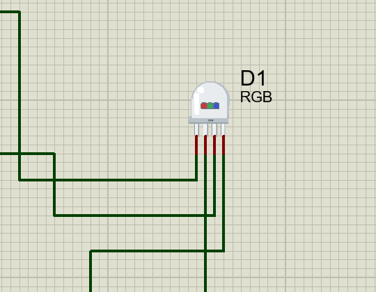
The longest leg is the common one. On the usual part, the order from one side is R, common, G, B, with the red leg next to the flat on the rim. Our symbol keeps that same order. Datasheets do vary, so on a real part, it is worth a quick test with a 3 V coin cell and a resistor before you solder anything.
Why Three Resistors?
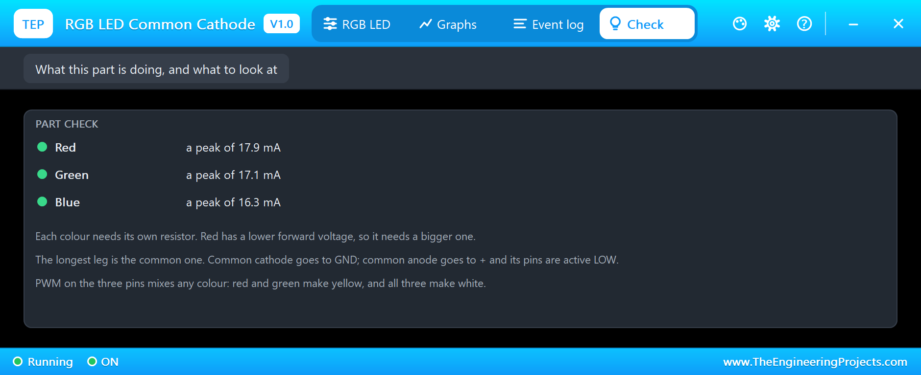
It is tempting to put one resistor on the common leg to save parts. That does not work. The three dies have different forward voltages, as you saw in our 5 mm LED Library for Proteus, and red is about 1 V lower than the others. With one shared resistor, red turns on first and pulls the voltage down, so blue and green hardly light at all. Each colour needs its own resistor, and red needs the biggest one:
| Colour | Forward voltage | Resistor for 20 mA from 5 V | In our demo |
|---|---|---|---|
| Red | 2.0 V | 150 ohm | 150 ohm |
| Green | 3.0 V | 100 ohm | 100 ohm |
| Blue | 3.1 V | 100 ohm (95 ohm exactly) | 100 ohm |
PWM Makes the Mix
An Arduino cannot set a true analog voltage on a pin, but it does not need to. PWM switches the pin fast, and the eye averages the flashes, so analogWrite(pin, 128) looks about half as bright. With one PWM pin for each colour, you get 256 levels of each, which gives more than sixteen million possible colours. Only pins marked with a ~ can do this: on an UNO, those are 3, 5, 6, 9, 10 and 11.
Other Colours
If you only need a fixed colour that an RGB LED makes badly, such as a true amber or a warm white, then a single-colour part is the better choice. We have those in our Designer Colour LED Library for Proteus. An RGB LED earns its place when the colour has to change: status lights, mood lamps and game controllers.
RGB or HSV?
Three numbers for red, green and blue are what the LED needs, but they are a clumsy way for people to think about colour. Most colour pickers use HSV instead: hue, saturation and value. The hue is the position on the colour wheel, the saturation is how strong the colour is, and the value is how bright. Moving through the rainbow is then simply a matter of changing one number, the hue, and that is exactly what our sketch does. A few lines of code turn that one number into the three levels the pins need.
Why Fades Look Wrong: Gamma
Here is something that surprises people. Set a channel to 128, half of 255, and it does not look half as bright. It looks much brighter than that. Your eye does not see light in a straight line: it is very sensitive in the dark and less so in bright light. So a straight fade from 0 to 255 seems to rush up at the start, and then crawl. Good colour lamps correct for this with a gamma table, a short list that bends the numbers to suit the eye. Our pop-up shows a brightness that follows the square root of the current, as a rough match for what you would really see.
Addressable RGB LEDs
Our part needs three pins for one LED. That is fine for one, but what about a strip of a hundred? For that, you can buy addressable LEDs such as the WS2812, often sold as NeoPixels. Each one has a tiny controller chip inside the package, and a single data wire runs from LED to LED, passing the colour along. That makes large displays easy. But they need precise timing and more power, and they cost more. For one status light or a small lamp, a plain RGB LED and three PWM pins is still the simple answer.
How Much Current Does It Take?
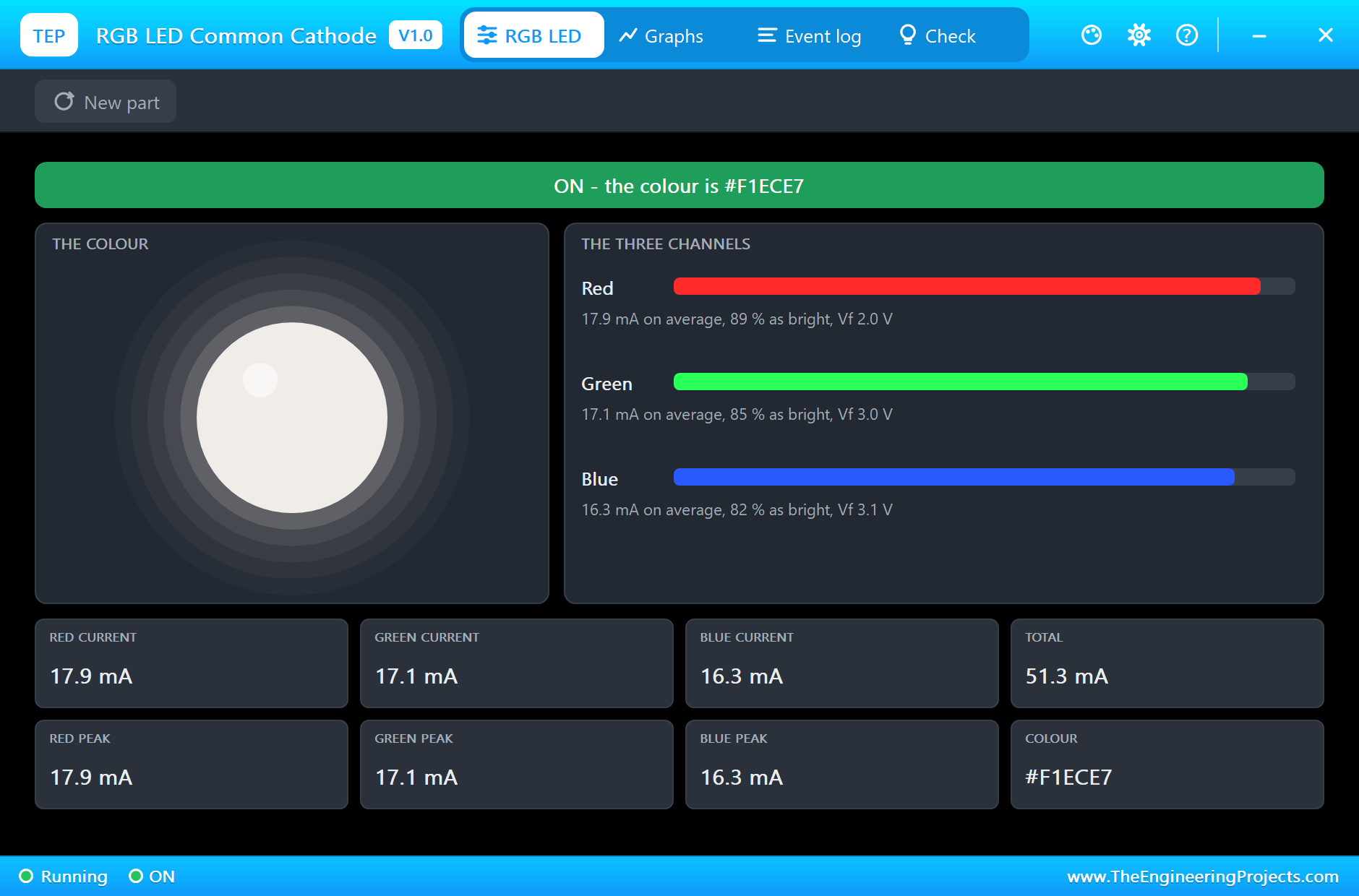
Remember that each colour is its own LED. At full white, our demo draws about 18 mA for red, 17 mA for green and 16 mA for blue, or 51 mA in total, all from three pins. That is fine for one part, but it adds up quickly. An UNO can supply about 200 mA in total from all its pins, so five RGB LEDs at full white would be at the limit. For more than a few, use transistors to switch each colour. In our pop-up, the Total tile adds up the three channels for you, so you can see this figure at a glance as the colour changes, which is a handy habit to get into before you build anything bigger.
A Common Anode Sketch
If your part is common anode, the only change to the code is to flip the numbers. A pin at HIGH now means no current, since both ends of the die are at 5 V, and a pin at LOW means full on. So analogWrite(pin, 255 - level) does the job. Many beginners wire up a common anode part, write a normal sketch, and wonder why the colours are upside down, and why full brightness turns it off. It is an easy thing to check first.
Features of the RGB LED Library for Proteus
- The real look, at true scale: the milky dome with three small dies, and four thin legs, with our small TEP signature.
- It really mixes: the dome on your sheet shows the mixed colour, live.
- Two devices: common cathode and common anode.
- Three true LEDs: each has its own forward voltage in the analog simulator.
- PWM works: the lag of the eye turns each pin's PWM into a brightness.
- One die can fail: over its limit, a colour burns out by itself, and the mix goes wrong.
- A pop-up for every part: click it at Run for the colour, the three channels, eight live values, graphs, an event log and a check page.
- A complete package: about 1.5 MB with the library, our Arduino UNO V4.0, the demo's resistors and the demo, without the source code of the models.
The RGB LED in Proteus
The two devices are LEDRGBCCTEP for common cathode and LEDRGBCATEP for common anode, in TEPRGB.LIB, under Optoelectronics, LEDs, with the prefix D and the model TEPRGB.DLL. Search LEDRGB in Pick Devices. The four pins are R, C, G and B, in that order, and C is the common leg.
The Properties
| Property | What it does |
|---|---|
| Red forward voltage at 20 mA, V | 2.0 by default |
| Green forward voltage at 20 mA, V | 3.0 by default |
| Blue forward voltage at 20 mA, V | 3.1 by default |
| Maximum current per colour, mA | 30 by default |
Download RGB LED Library for Proteus
Click the button below to download RGB-LED-Library-for-Proteus-v1.0.zip (about 1.5 MB, without the source code of the models):
RGB LED Library for Proteus V1.0- README.txt: installation, the demo, the properties, troubleshooting and the limits.
- Proteus Library Files:
TEPRGB.LIB,TEPRESISTOR.LIBand ourArduinoV4TEP.LIB. - Proteus Model Files:
TEPRGB.DLL,TEPRESISTOR.DLLandTEPARDUINO.DLL. - Arduino Code: the demo sketch.
- Proteus Simulation: the demo project, its HEX file and copies of the DLLs.
No Proteus yet? Read How to Download and Install Proteus 7 and 8. New to libraries? Follow How to Install a New Library in Proteus.
How to Install RGB LED Library for Proteus
- Close Proteus and extract the whole zip file, for example to your Desktop.
- Copy the files from Proteus Library Files into the LIBRARY folder of Proteus.
- Copy the files from Proteus Model Files into the MODELS folder.
- Delete
TEPRGB.IDXfrom the LIBRARY folder if it is there. - Start Proteus, press P and search for LEDRGB.
Demo: An Arduino Colour Mixer
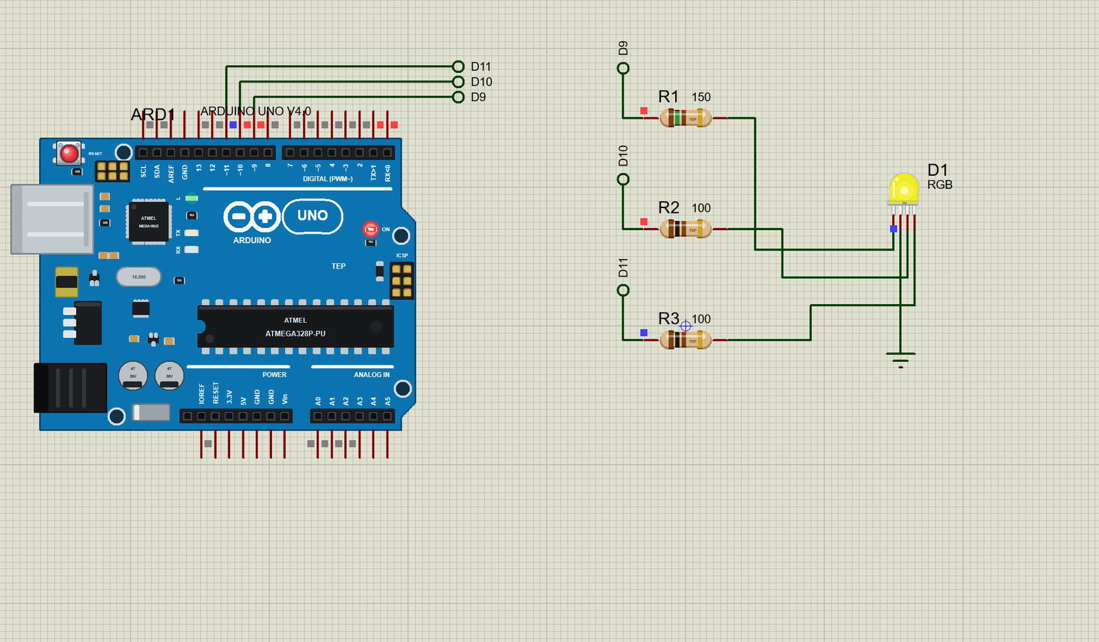
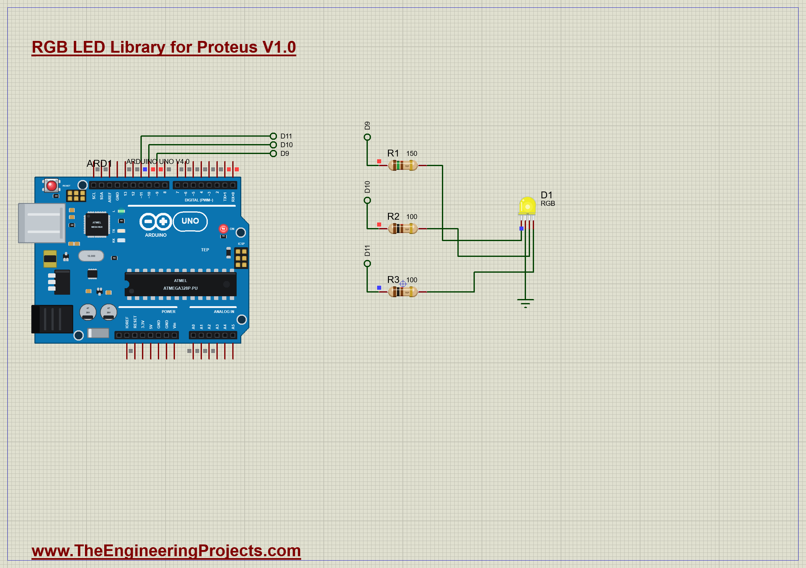
The demo is one RGB LED on three PWM pins, D9, D10 and D11, each through its own resistor. The common leg goes to GND. Open RGB-LED-Colour-Mixer-ArduinoUnoV4.pdsprj. It runs on our Arduino UNO Library for Proteus V4.0, with its built-in monitor, the same window as our TEP Serial Monitor Advance for Proteus. The resistors are from our Resistor Library for Proteus.
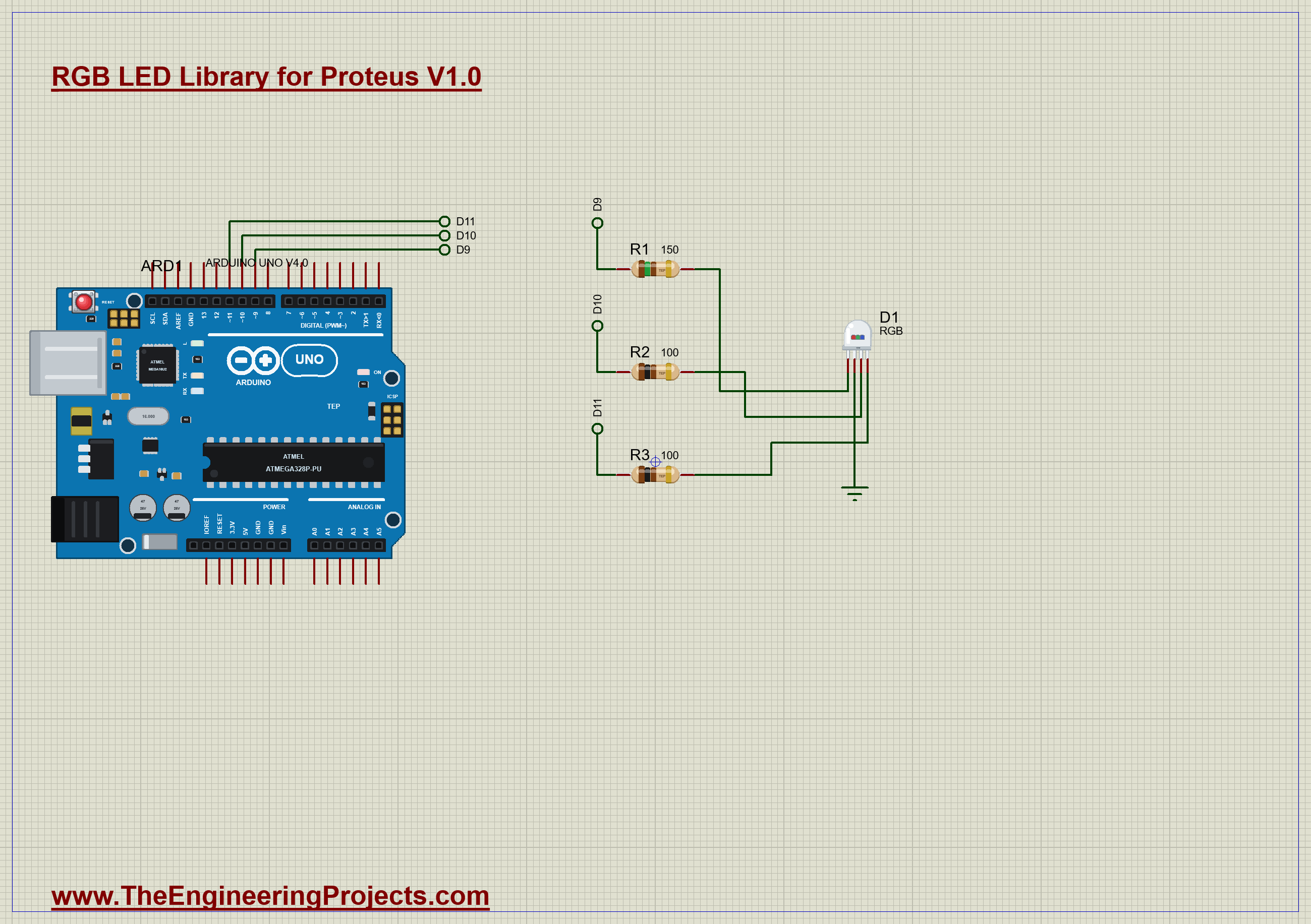
| Part | Connection | Job |
|---|---|---|
| R1, 150 ohm | D9 to R | the red channel |
| R2, 100 ohm | D10 to G | the green channel |
| R3, 100 ohm | D11 to B | the blue channel |
| D1 | C to GND | the RGB LED |
The Colour Wheel
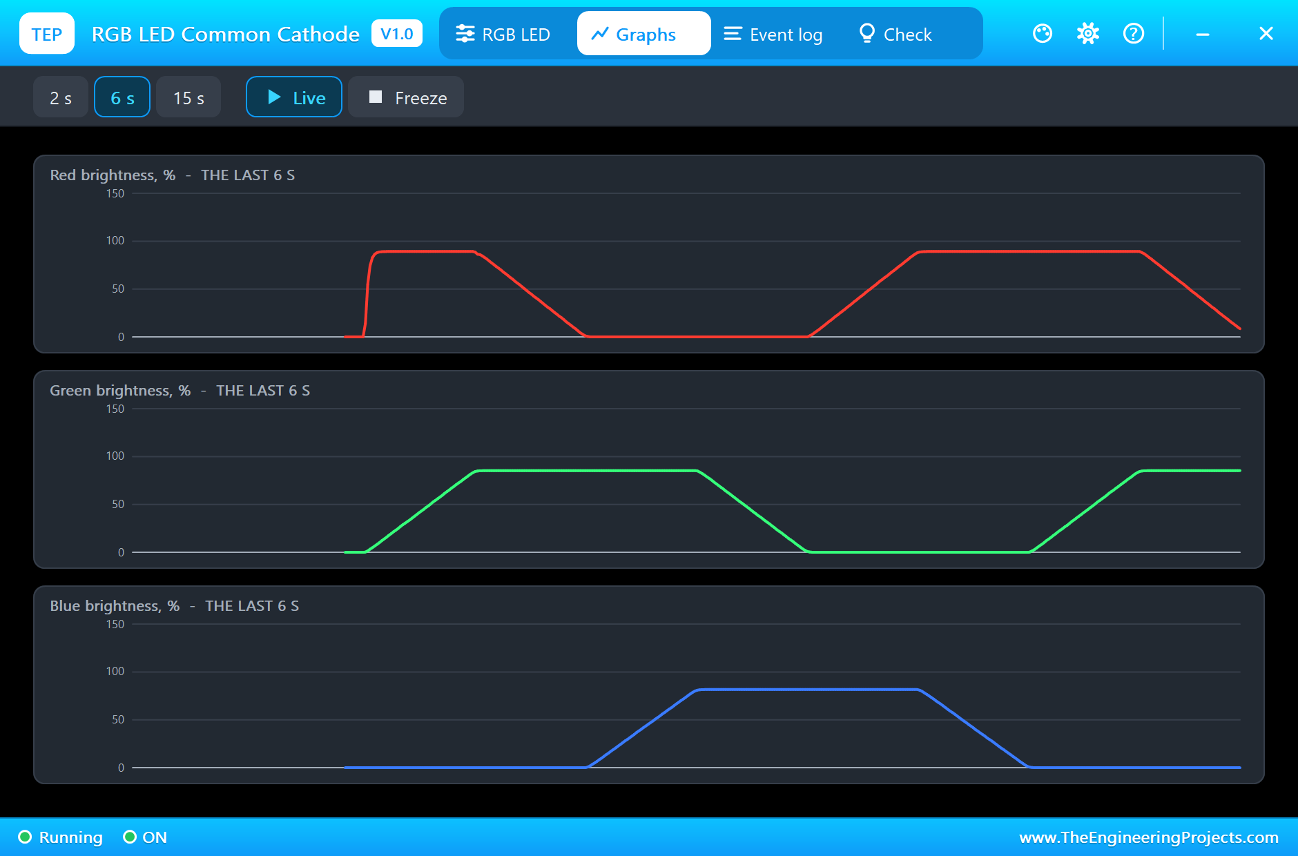
The sketch starts by fading round the wheel of colours. A hue is an angle from 0 to 359 degrees, and the wheel has six slices. In each slice, one channel is full, a second is fading up or down, and the third is off. That single idea gives every bright colour:
  switch (part) {
    case 0: show(255, rise, 0); break;
    case 1: show(fall, 255, 0); break;
    case 2: show(0, 255, rise); break;
    case 3: show(0, fall, 255); break;
    case 4: show(rise, 0, 255); break;
    default: show(255, 0, fall); break;
  }
The Commands
| Type this | What happens |
|---|---|
| red, green, blue | one colour |
| yellow, cyan, magenta | two colours mixed |
| white | all three |
| off | all off |
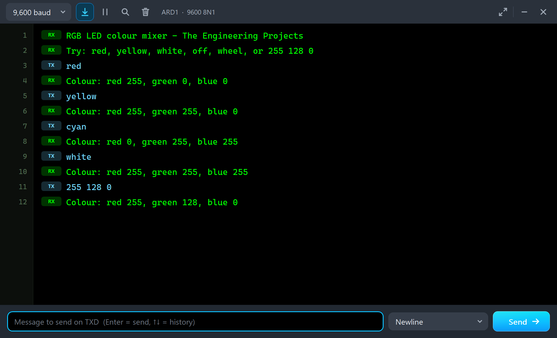
| 255 128 0 | any colour: red, green and blue, from 0 to 255 |
| wheel | back to fading round the wheel |
Run the Demo
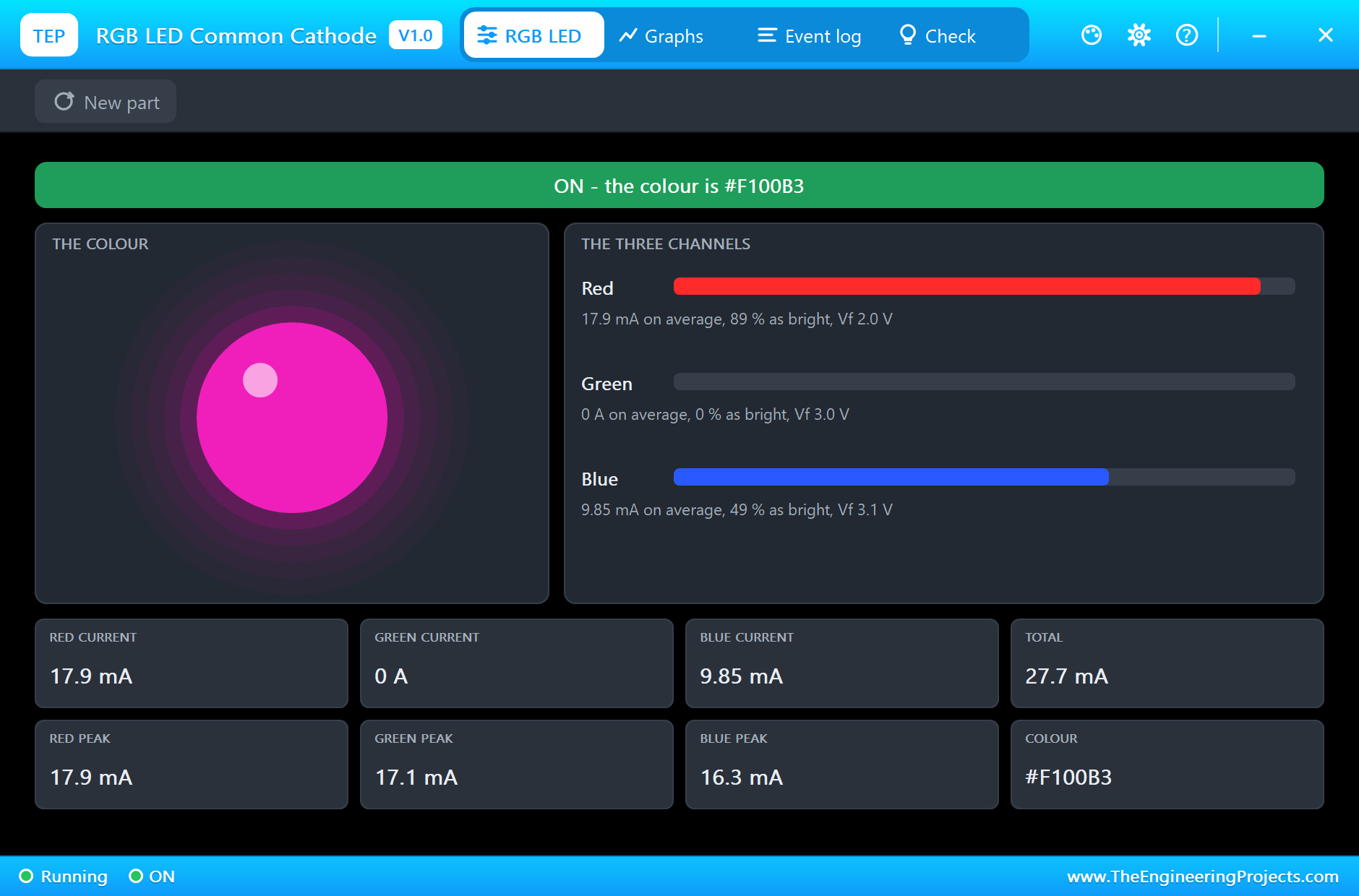
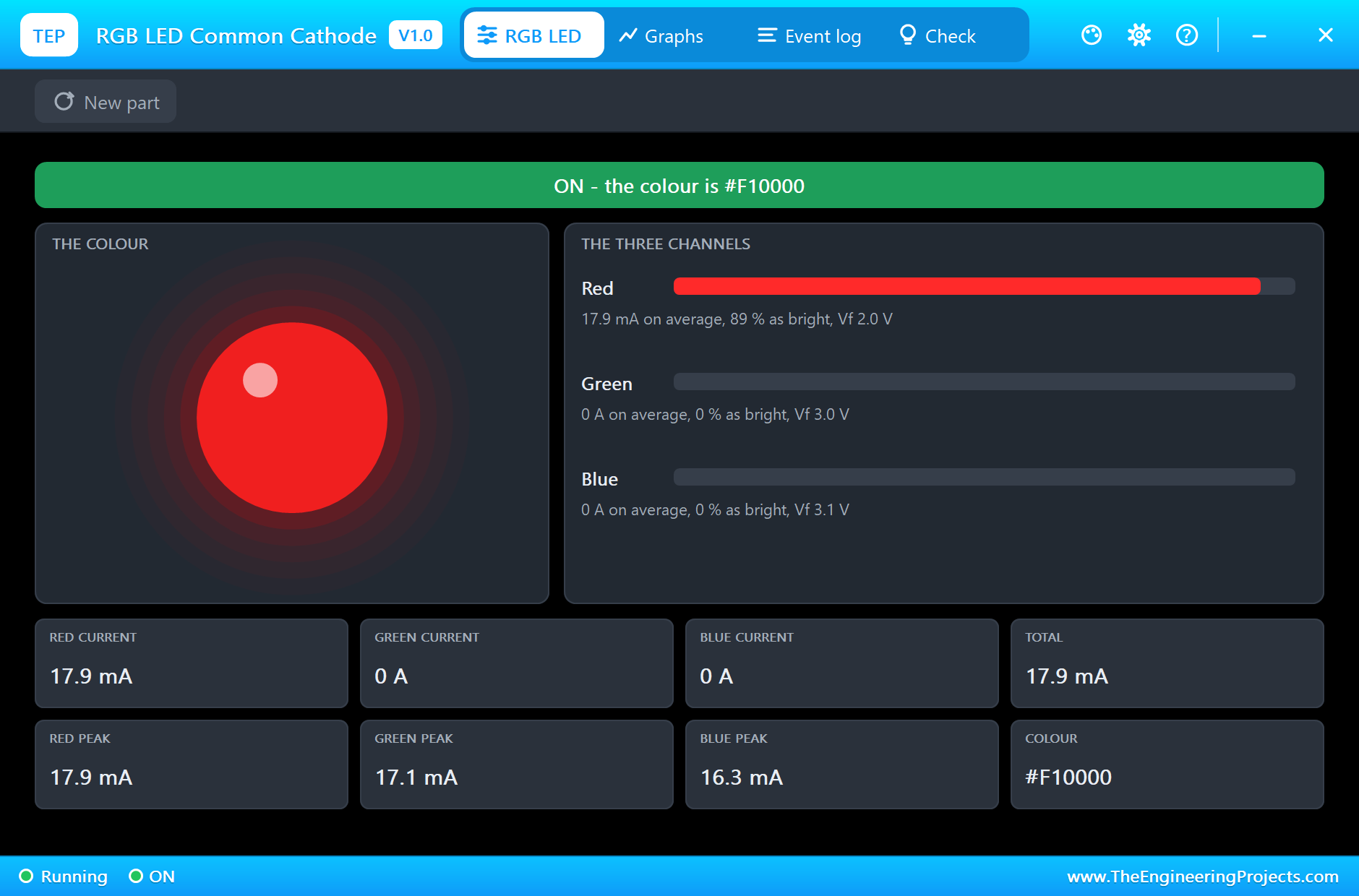
Press Run. The dome starts drifting through the colours. Click it to open its pop-up. On the left is the colour it makes, and on the right are the three channels that make it:
The Graphs tab shows how the wheel works, with the three channels taking turns:
Mixing by Hand
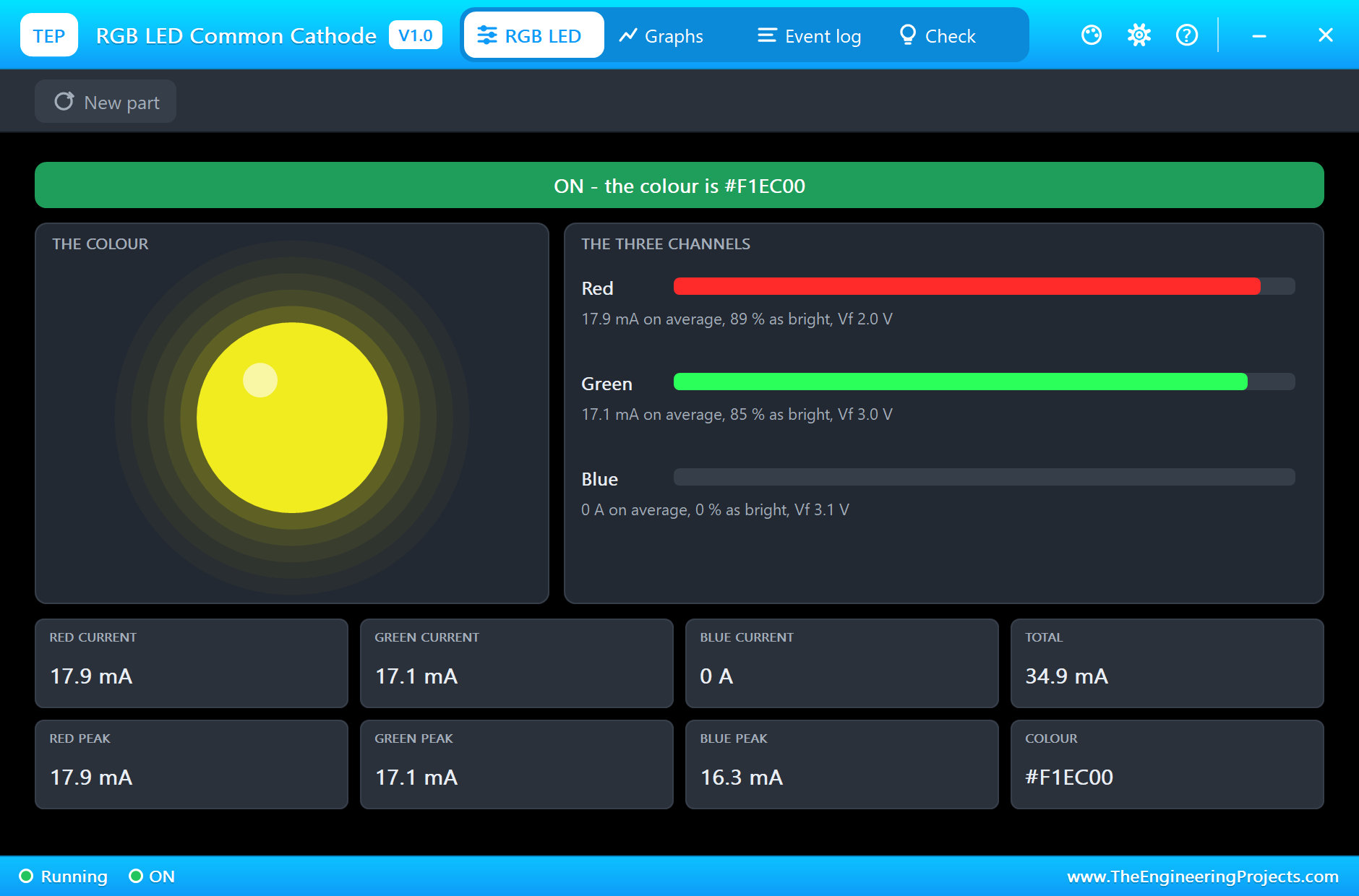
Type red in the monitor. Only one bar is full. Now type yellow. There is no yellow die in there, so the LED makes it from red and green together:
And here is the same colour on the sheet, with the complete circuit truly running:
Type cyan for green and blue together, and watch the dome change:
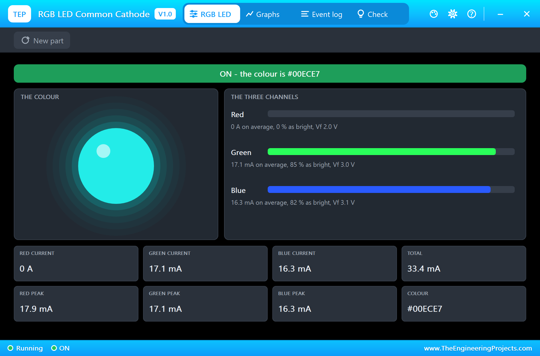
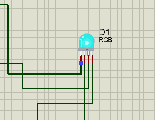
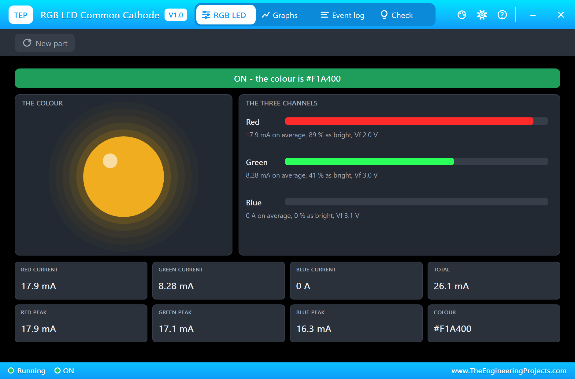
Now type white. All three channels are full, and each one draws its own current. Finally, type 255 128 0 for any colour you like. Half of green with all of red gives orange:
The Log and the Check Page
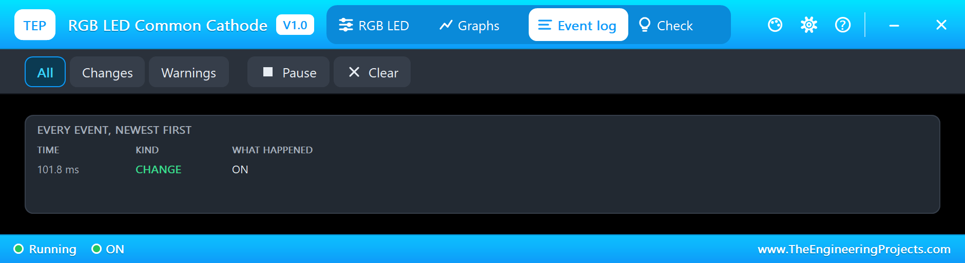
The Event log records the part going on and off, and the Check page looks at each colour against its limit:
Try It Yourself
- Change R1 to 47 ohm, and see the Check page warn you about red.
- Swap the D9 and D10 wires, and see every colour change.
- Use the common anode part. The common leg goes to +5V, and you must flip the numbers in the sketch: 255 - value.
- Slow the wheel down, and find your favourite colour.
- Set the green forward voltage to 2.2 V, as on an older part, and compare the current.
Ideas to Extend the Demo
- Set the colour with three potentiometers.
- Show a temperature as a colour, from blue to red.
- Make a status light: green is fine, amber is a warning, and red is a fault.
- Fade smoothly from one colour to the next, with a small table of colours.
Your Own Sketches
The demo sketch is in the zip file, and you can change it in the Arduino IDE. New to Arduino? Start with our Arduino Tutorial for Beginners. Export the compiled binary, and set the UNO's PROGRAM property to the new file. Our guide on How to get the HEX file from Arduino shows you where the file ends up.
Things to Know Before Using a Real RGB LED
- One resistor per colour: a shared resistor gives poor mixing.
- Check the pinout: legs vary between makers, so test it first.
- White may not be white: the three dies differ in brightness, so you may need less of one colour.
- Mind the total current: at full white, one LED draws 60 mA, which is close to the limit of a group of pins.
- Your eye is not straight: it sees brightness on a curve, so a fade looks better with a gamma table.
Troubleshooting
- One colour is missing: that die has burnt out, or its pin cannot do PWM.
- It looks the wrong colour: check which pin goes to which leg.
- It stays lit when it should be off: on a common anode part, a HIGH pin is off.
- BURNT OUT: use more ohms, then press New part.
- The part is not simulated:
TEPRGB.DLLis missing from MODELS and from the project folder.
Limitations of the Simulation
- The three dies are treated as equally bright, and the viewing angle is left out.
- The colour on the sheet follows the square root of the current, as a rough match for the eye.
- The sheet repaints at most four times a second.
- Arduino is a name of Arduino; this library is not made or endorsed by Arduino or Labcenter.
- Tested in Proteus 8.5 in October 2026 (the demo as shipped). Proteus 7 is not supported.
So, that was all about the RGB LED Library for Proteus. I hope you have as much fun with the colours as we did, and that a little yellow dome on a Proteus sheet makes you smile too. If you have any questions, ask in the comments and I will help you out. Till the next tutorial, take care and have fun!

Comments
0