


Getting Started With Microcontrollers


Hello friends! Today, we are starting our microcontroller tutorial series from the basics. Before connecting a PIC, installing a compiler or writing an LED-blinking program, we need to understand what a microcontroller does and how its software interacts with an electrical circuit.
Think of a project that reads a push button, changes a pattern of lights and reports its operating state. A microcontroller can coordinate those actions by repeatedly reading inputs, applying programmed rules and updating outputs. The same basic idea appears in sensor loggers, small robots, appliance controls and many other embedded systems.
In this series, our detailed hardware example will be the PIC18F452. We will first learn the general ideas, then study that device's connections and development tools. You do not need to understand every register today; the aim is to build a clear foundation for the practical lessons that follow.
What Is a Microcontroller?
A microcontroller is an integrated circuit that combines a processor with memory and hardware interfaces. Its processor executes instructions, its memory stores the program and working data, and its peripherals connect the program to signals outside the chip.
The program stored in the device is often called firmware. Once power and the required supporting conditions are present, the controller begins executing from its startup path. It does not need a person to type each instruction individually. The firmware defines what happens at startup and what the system does afterward.
For example, a temperature controller might read a sensor, compare the reading with a setpoint and switch a fan through a suitable driver. The microcontroller makes the decision, but the sensor measures the temperature and the power circuit supplies the fan current. Understanding those separate responsibilities prevents many beginner wiring mistakes.
How a Microcontroller Changes a Project
Consider a row of decorative lights. A fixed circuit can create a pattern, but changing the order or timing may require altering the hardware. With a programmed controller, we can store the pattern as data and change the sequence in firmware, provided the existing output circuitry can still support the new behavior.
This flexibility does not mean software can repair every hardware limitation. If an output circuit cannot handle a lamp's current, a code change cannot increase the transistor's rating. If the selected controller has no suitable interface for a sensor, the design may need additional hardware or another device.
A useful way to describe an embedded project is to divide it into measurement, decision and action. The input circuitry turns a physical event into an electrical signal. The firmware interprets that signal. The output circuitry changes something in the world or communicates the result.
The Main Parts Inside the Chip
| Part | Role | Example use |
|---|---|---|
| CPU | Executes instructions and performs calculations | Compares a measured value with a threshold |
| Program memory | Stores executable firmware | Holds the control program after programming |
| RAM | Holds changing working data | Stores a receive buffer or running total |
| Nonvolatile data storage | Retains selected settings without power, when provided | Stores a calibration value |
| GPIO | Provides configurable digital inputs and outputs | Reads a button or drives an LED interface |
| Timers | Measure or generate intervals and count events | Schedules a periodic sample |
| Communication peripherals | Exchange data using supported protocols | Reads an I2C sensor or transmits a serial record |
| Analog peripherals | Interface with analog signals, where present | Converts an input voltage to a numeric code |
Not every microcontroller contains the same combination of these features. Some have a large number of analog channels, others emphasize communication or low-power operation. The exact part number and datasheet matter more than the general family name.
Program Memory Is Different from RAM
Program memory holds the firmware image. RAM holds variables while the program runs and normally loses its contents when power is removed. A device can have enough room for its program but still run out of RAM because the application uses large arrays or buffers.
As a simple calculation, storing 100 readings as 16-bit integers requires 100 × 2 = 200 bytes for the readings alone. Timestamps, array bookkeeping, other variables and the call stack require additional space. Count the complete working set rather than comparing only the source-code file size with the chip's memory specification.
Microcontroller, Development Board and FPGA
These terms are related to embedded development, but they do not describe the same thing. The original version of this lesson mixed manufacturer names, chip families and boards in one list. The following distinction is more useful.
| Term | Meaning |
|---|---|
| Microcontroller | A chip containing a processor, memory and peripherals |
| Microcontroller family | A group of related devices, such as PIC or AVR families |
| Manufacturer | The company producing or supplying the device |
| Development board | A circuit board that makes a controller easier to power, program and connect |
| FPGA | Programmable logic hardware that can implement digital circuits; not simply another ordinary microcontroller family |
An Arduino UNO R3 is a development board built around an ATmega328P microcontroller, as described in Arduino's board documentation. The board adds supporting circuitry, connectors and a convenient development workflow. Other Arduino boards use different processors, so the word Arduino alone does not identify a chip architecture.
A bare PIC and an Arduino board therefore should not be compared as if both were equivalent packages. A PIC development board can also include a regulator, clock, programming interface and connectors. A custom design using an ATmega328P must still provide the supporting circuitry its application requires.
Understand Inputs and Outputs
A digital input distinguishes logic states according to the device's electrical thresholds. It does not magically know whether a switch is open or closed. The surrounding circuit must give the input a defined voltage in each state, often using a pull-up or pull-down resistor.
An unconnected input may float and change state unpredictably. If a button connects an input to ground, a suitable pull-up establishes the opposite state when the button is released. The firmware must then interpret pressed as a low level rather than assuming that every active input is high.
A digital output can source or sink only a limited current. An LED needs current limiting; a relay or motor normally needs a driver. Check individual-pin limits, grouped-port limits and the device's total current limits. An absolute maximum rating is a damage boundary, not a preferred operating point.
Calculate an LED Resistor
Suppose a 5 V output drives an LED with an approximate 2 V forward drop, and we choose 5 mA as the design current. The ideal series resistance is R = (5 − 2) / 0.005 = 600 ohms. A 680-ohm resistor gives approximately 4.4 mA with those assumed voltages.
The actual current depends on the LED and output voltage. Check that the controller can provide it under the intended operating conditions. The calculation explains how to choose a starting resistance; it does not remove the need to read the electrical specification.
Analog Measurements and Resolution
An analog-to-digital converter represents an input voltage with a finite set of codes. A 10-bit converter has 210 = 1024 possible codes. With an ideal 0–5 V reference span, one nominal code interval is 5 / 1024, approximately 4.88 mV.
Resolution is not the same as accuracy. A reference-voltage error, sensor offset or noisy input can affect the result even when the converter reports many digits. Also check the permitted input-voltage range and the source requirements for the converter's acquisition process.
For a sensor project, keep three steps distinct: the sensor's physical measurement, its electrical output and the ADC's numeric representation. A conversion formula links those steps. Without the sensor's scale and offset, a raw ADC count is not automatically a temperature, pressure or distance.
Clocks, Timers and Program Timing
The controller's clock provides the timing basis for instruction execution and many peripherals. The oscillator frequency is not automatically equal to the number of useful application operations completed each second. Instruction timing, memory access and peripheral configuration all matter.
A timer counts clock-derived ticks or external events. If its tick rate is 1000 ticks per second, 250 ticks represent 0.25 seconds. The timer's width determines when it wraps, and its prescaler changes the relationship between the source clock and timer ticks.
Busy-wait delays are easy to understand in a first LED demonstration, but they can make a program unresponsive. If the firmware waits for half a second after switching an LED, it may not check a button during that interval. A timer-based schedule allows the application to keep reading inputs while waiting for the next output change.
Polling and Interrupts
Polling means that the program repeatedly checks whether something needs attention. For example, the main loop reads a button and checks whether a timer interval has elapsed. This approach is easy to trace and often sufficient for a small project.
An interrupt lets hardware request attention when an enabled event occurs. The processor runs a designated service routine and then returns to its previous work. Interrupts are useful for events that would be inconvenient or unreliable to detect through occasional polling.
Keep interrupt routines short. Record the event, capture essential data and leave longer processing to the main program where possible. Printing a long diagnostic message or waiting for a user action inside an interrupt can prevent other work from proceeding in time.
How the Program Reaches the Microcontroller
First we write source code in a language supported by the development tools. A compiler or assembler translates it, and a linker combines the program's parts into an image for the selected device. A programmer then transfers that image to the target through a supported programming interface.
The IDE is the workspace that organizes editing, project settings, builds and debugging. It is not identical to the compiler. For PIC development, Microchip provides MPLAB X IDE and separate toolchains such as MPLAB XC8. Choose compatible versions for the exact target and programming hardware.
A development board may already contain a bootloader that receives programs through another interface. That is one possible programming workflow, not a property of every bare microcontroller. A new chip does not necessarily contain the bootloader expected by a particular board environment.
Our PIC18F452 Learning Platform
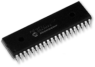
The PIC18F452 is an 8-bit PIC device used in the original tutorials. The 40-pin PDIP version is convenient for studying a labelled pinout and building a breadboard circuit. Other packages have different physical pin numbering, and similarly named devices are not automatically interchangeable.
Use Microchip's PIC18F452 product information and PIC18FXX2 datasheet as the reference for this series. We will examine power, reset, clock and programming connections before assigning application functions to the remaining pins.
Learning this older device can still teach useful fundamentals. For a new product, choose a controller from the application's requirements and the support available to you rather than assuming that the tutorial's historical part is always the best choice.
Build the First Project in Small Steps
- Identify the exact device and package.
- Read the supply, reset, clock and programming requirements.
- Create a small project targeting that device.
- Build a minimal circuit with one current-limited LED.
- Program a simple output test and observe the result.
- Add one button with a defined input state.
- Replace long blocking delays with a timer-based schedule when responsiveness becomes important.
A blinking LED is useful because it tests several things at once: power, startup, clock configuration, programming and output control. If it does not blink, resist the temptation to add a display and several sensors. Reduce the problem until each of those basic conditions is understood.
Then test a button and LED together. Mechanical buttons can produce several rapid transitions during one press, so the program may need debouncing. A simple demonstration can accept a new button state only after it remains stable for a chosen interval. Select that interval from the switch behavior and response requirements rather than treating one number as correct for every application.
Choose a Controller from Requirements
| Question | What to check |
|---|---|
| How many signals must connect? | Usable pins after reserving clock, reset and programming functions |
| Which interfaces are needed? | UART, SPI, I2C, USB or other required peripherals |
| How much data is buffered? | RAM usage, including stack and communication buffers |
| How fast must the system react? | Worst-case execution time and peripheral timing |
| What powers the system? | Supply range, sleep modes and total circuit consumption |
| How will it be maintained? | Programming access, debugging tools and reproducible builds |
Write a pin-allocation table before wiring. A device may advertise several peripheral functions, but some share the same physical pin. You cannot always use every advertised feature simultaneously in the exact arrangement your first sketch assumes.
Estimate Power for the Whole Circuit
For a battery project, include the controller, sensors, regulators, indicator LEDs and communication hardware in the current budget. An ideal 1000 mAh battery supplying a constant 20 mA load gives 1000 / 20 = 50 hours by a simple capacity calculation. Real runtime depends on usable capacity, discharge conditions, conversion efficiency and changing load. Putting the controller to sleep helps only if the rest of the circuit is also considered. A permanently powered sensor or bright indicator can dominate the consumption even when the processor spends most of its time asleep.
Common Beginner Mistakes
Many early problems come from an incorrect device selection, a missing ground, a floating reset pin or a clock setting that does not match the circuit. Another common mistake is configuring a multiplexed pin as an analog input and then expecting it to behave as an ordinary digital input without changing that configuration.
Software mistakes often involve uninitialized variables, buffers that exceed RAM, or loops that block indefinitely waiting for a peripheral. Give communication operations a defined timeout and decide what the application should do when a sensor is absent. An embedded program must handle the environment it actually encounters, including imperfect connections.
Review and Tutorial Sequence
We now have the basic picture: a microcontroller executes firmware, uses memory and peripherals, and interacts with the surrounding circuit. The circuit and program must agree about signal levels, pin functions and timing. Next, we will apply those ideas to the PIC18F452.
- Getting started with PIC microcontrollers
- PIC18F452 functions and pins
- Installing MPLAB in Windows
- Installing the MPLAB C compiler
- Creating the MPLAB project
- LED blinking with a PIC
Frequently Asked Questions
Does an 8-bit microcontroller process only numbers below 256?
No. It can process larger values using multiple bytes and suitable instructions. The data width affects how operations are implemented, but it does not forbid multi-byte arithmetic.
Can I connect a motor directly to an output pin?
Use a driver suitable for the motor's current and voltage. Include the protection and power arrangement required by the load. The microcontroller pin provides a control signal rather than the motor's power supply.
Must I learn assembly before writing C?
You can begin with C while learning the device's registers and hardware behavior. Assembly knowledge can help explain generated code and timing, but it is not a prerequisite for every beginner C project.
Can firmware changes replace circuit changes?
They can change behavior within the hardware's capabilities. They cannot add missing voltage tolerance, current capacity or physical connections. Evaluate both sides of the design when a requirement changes.

Tags


Good morning sir! Please am using pickit3 as my programmer but I was unable to burn my code bcos my system is not recognizing the port.
Comments
1