


Bridge Rectifier Library for Proteus: DB107 and AC from Two Pins


Hello friends, I hope you all are doing great. Today, I am going to share the new Bridge Rectifier Library for Proteus. Every phone charger, laptop adapter and appliance that plugs into the wall has to turn AC into DC, and nearly all of them start with the same small block: four diodes in one package, called a bridge rectifier. It is one of the neatest tricks in electronics.
Bridge Rectifier Library for Proteus
Latest version: V1.0 (November 2026, this tutorial)
Helping Tools
- Serial Monitor Advance: a serial terminal window for the UART of your board
- Serial Monitor Expert: the serial monitor with extra debugging tools
- LCD Library for Proteus V3.0: 16x2, 20x4 and I2C LCDs to show your readings
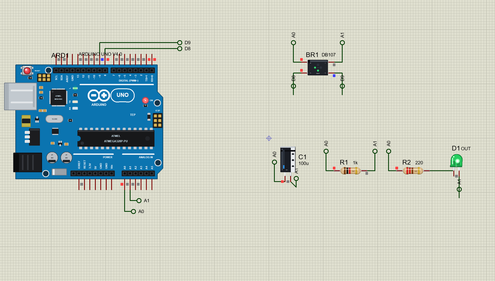
Our part is the popular DB107, at true scale, with a tiny lamp for each of its four diodes, so you can watch the pairs take turns. The pop-up draws the four diodes in their famous diamond, with the live path of the current lit up. And for the demo we get real AC with no mains and no transformer: two Arduino pins, switching in opposite ways, make a square wave that really does swing from plus 5 V to minus 5 V.
NOTICE: Our team has put a lot of effort into these small parts: the bodies, the animation and the pop-ups are all our own design, and you get them free. Your feedback is the fuel that keeps us going, so please tell us what you think in the comments below or in the Bridge Rectifier board of our forum. And if our free libraries help you, you can buy us a coffee. So, let's get started with the Bridge Rectifier Library for Proteus:
What is a Bridge Rectifier?
In our 1N4007 Diode Library for Proteus, one diode made a half-wave rectifier. It uses only the positive half of each AC cycle and simply throws the other half away. A bridge rectifier uses four diodes to rescue that lost half. It takes both halves of the AC and sends them to the output the same way round, and this is called full-wave rectification. So you get twice as many pulses, far less ripple, and more power from the same transformer.
The four diodes sit in a square, or diamond, and the two corners of one diagonal take the AC, while the two corners of the other give the DC. You could wire four 1N4007 diodes yourself, and many people do. But a ready-made bridge is smaller, cheaper to fit and easier to mount on a heat sink, so most products use a single block.
| Feature | The real part | In the library |
|---|---|---|
| Body | DB107, 8.5 x 6.4 mm | 357 x 269 thou, true scale |
| Reverse voltage | 1000 V | the same class of diode |
| Forward current | 1 A on average | the Check page warns over it |
| Forward drop | two diodes, about 1.4 V | the same, from the diode law |
| Legs | + - ~ ~ | the same |
How Does It Work?
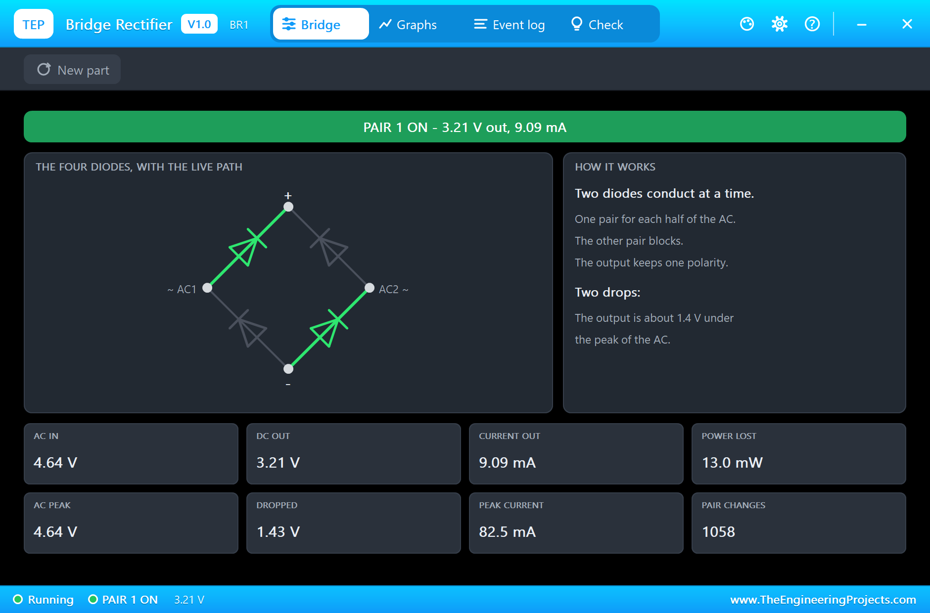
Follow the current through one half of the cycle. Say the left AC leg is positive. Current flows through one diode to the + output, through the load, back to the - output, through a second diode, and out of the right AC leg. The other two diodes block. On the next half the AC turns round, and now the other two diodes carry the current. The clever part is this: in both cases, the current goes through the load in the same direction. That is the whole trick.
The Two Diode Drops
There is a small price. The current always passes through two diodes in series, one on the way out and one on the way back. So the DC output is two drops below the peak of the AC, about 1.4 V for silicon. On a 230 V supply nobody notices. On a 5 V transformer, it is a big bite, and designers may turn to Schottky diodes or even to transistors to reduce it.
From the Peak to the DC
Here is a sum that catches many beginners. A 12 V transformer does not give a peak of 12 V. The 12 V is an RMS figure, and the true peak is 1.414 times higher, about 17 V. After two diode drops, and with a large smoothing capacitor, you get close to 15.6 V with a light load, not 12 V. So always work from the peak when you choose your capacitor and your regulator.
| AC RMS | Peak | Smoothed DC, light load |
|---|---|---|
| 6 V | 8.5 V | about 7.1 V |
| 9 V | 12.7 V | about 11.3 V |
| 12 V | 17 V | about 15.6 V |
| 24 V | 33.9 V | about 32.5 V |
Half-Wave or Full-Wave?
A half-wave rectifier gives one pulse per cycle, so on 50 Hz mains the capacitor has to hold up the output for 20 ms. A bridge gives two pulses per cycle, so it only has to hold on for 10 ms. For the same ripple you need half the capacitance, or with the same capacitor you get half the ripple. That is why a half-wave rectifier is rarely used for anything but very small loads.
Choosing a Smoothing Capacitor
After the bridge, the output is a row of humps. A capacitor fills the valleys between them, and the size follows from a simple sum: ripple = I / (2 x f x C), where I is the load current, f is the mains frequency and C is the capacitor. A handy rule on 50 Hz mains is about 1000 uF for each 100 mA, and that gives about 1 V of ripple. For a regulator that needs a few volts of headroom, that is usually fine. Choose a capacitor rated well over the peak voltage, as our electrolytic library explains.
Building One From Four Diodes
Nothing stops you from making a bridge out of four separate diodes, and it is a good exercise. Draw the diamond with all four arrows pointing towards the + corner, and it is hard to get it wrong. The two side corners take the AC. Check it by following the current for each half of the cycle with your finger. If you ever have a dead bridge in a repair, four 1N4007 parts will replace a small one in a pinch.
Better Than Diodes
Those two drops waste real power. In a supply that delivers 10 A, a bridge burns about 14 W as heat, all the time. So modern high-efficiency supplies often replace the diodes with MOSFETs that are switched on at exactly the right moment, and this is called an active bridge or synchronous rectifier. It needs a control chip, so it only pays at high power. For almost everything else, the simple four-diode block is still the best answer, after more than half a century.
Bridges Beyond the DB107
The same idea scales from tiny to huge. Surface-mount parts like the MB10S fit on a phone charger board, and square metal blocks with a hole for a screw carry 35 A on a welder or a battery charger. Three-phase versions use six diodes, and they sit in wind turbines and electric vehicle chargers. Our own PM generator library uses that same idea to turn a turning shaft into DC. Whatever the size, the trick inside is the one you see on this little black block.
Features of the Bridge Rectifier Library for Proteus
- The real look, at true scale: the black block with its + - ~ ~ marks, four legs and a bevel at the + corner, with our small TEP signature.
- A lamp for each diode: small green lamps show which pair conducts.
- Four true diodes: each with the real diode law, on four separate pins.
- A live path: the pop-up draws the diamond, and lights the diodes that are carrying the current.
- Live measurements: AC in, DC out, the current, the power lost and the number of pair changes.
- It fails like the real thing: too much power cooks it, and it fails short across the AC side.
- A complete package: about 2.1 MB with the library, our Arduino UNO V4.0, the demo's resistors, LED and capacitor and the demo, without the source code of the models.
The Bridge Rectifier in Proteus
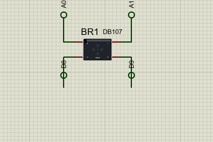
The device is BRIDGEDB107TEP in TEPBRIDGE.LIB, under Diodes, Bridge Rectifiers, with the prefix BR and the model TEPBRIDGE.DLL. Search BRIDGEDB107 in Pick Devices. The pins are P for +, N for -, and AC1 and AC2 for the two ~ legs. There are no properties to set.
Download Bridge Rectifier Library for Proteus
Click the button below to download Bridge-Rectifier-Library-for-Proteus-v1.0.zip (about 2.1 MB, without the source code of the models):
Bridge Rectifier Library for Proteus V1.0- README.txt: installation, the demo, troubleshooting and the limits.
- Proteus Library Files:
TEPBRIDGE.LIB,TEPRESISTOR.LIB,TEPLED5MM.LIB,TEPELECTRO.LIBand ourArduinoV4TEP.LIB. - Proteus Model Files:
TEPBRIDGE.DLL,TEPRESISTOR.DLL,TEPLED5MM.DLL,TEPELECTRO.DLLandTEPARDUINO.DLL. - Arduino Code: the demo sketch.
- Proteus Simulation: the demo project, its HEX file and copies of the DLLs.
No Proteus yet? Read How to Download and Install Proteus 7 and 8. New to libraries? Follow How to Install a New Library in Proteus.
How to Install Bridge Rectifier Library for Proteus
- Close Proteus and extract the whole zip file, for example to your Desktop.
- Copy the files from Proteus Library Files into the LIBRARY folder of Proteus.
- Copy the files from Proteus Model Files into the MODELS folder.
- Delete
TEPBRIDGE.IDXfrom the LIBRARY folder if it is there. - Start Proteus, press P and search for BRIDGEDB107.
Demo: Real AC from Two Arduino Pins
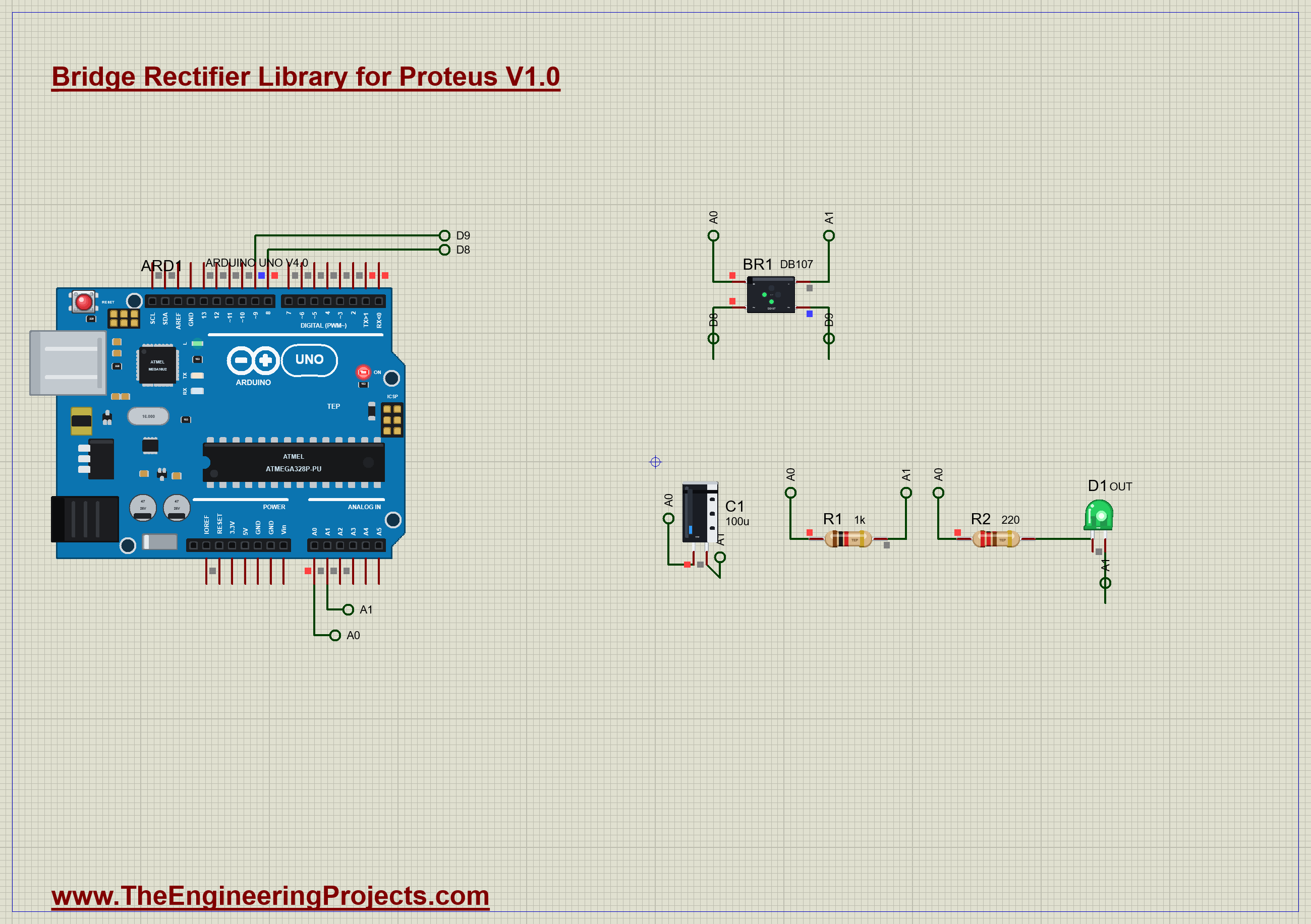
Here is a neat idea. An Arduino pin can only be 0 V or 5 V, so one pin cannot make AC. But look at the voltage between two pins. When D8 is HIGH and D9 is LOW, the difference is plus 5 V. Swap them, and the difference is minus 5 V. So two pins, toggling in opposite ways, make a true square wave of 10 V from peak to peak, floating, just like the two wires from a transformer. Open Bridge-Rectifier-ArduinoUnoV4.pdsprj. It runs on our Arduino UNO Library for Proteus V4.0, with its built-in monitor, the same window as our TEP Serial Monitor Advance for Proteus. The resistors are from our Resistor Library for Proteus, the LED from our 5 mm LED Library for Proteus and the capacitor from our Electrolytic Capacitor Library for Proteus.
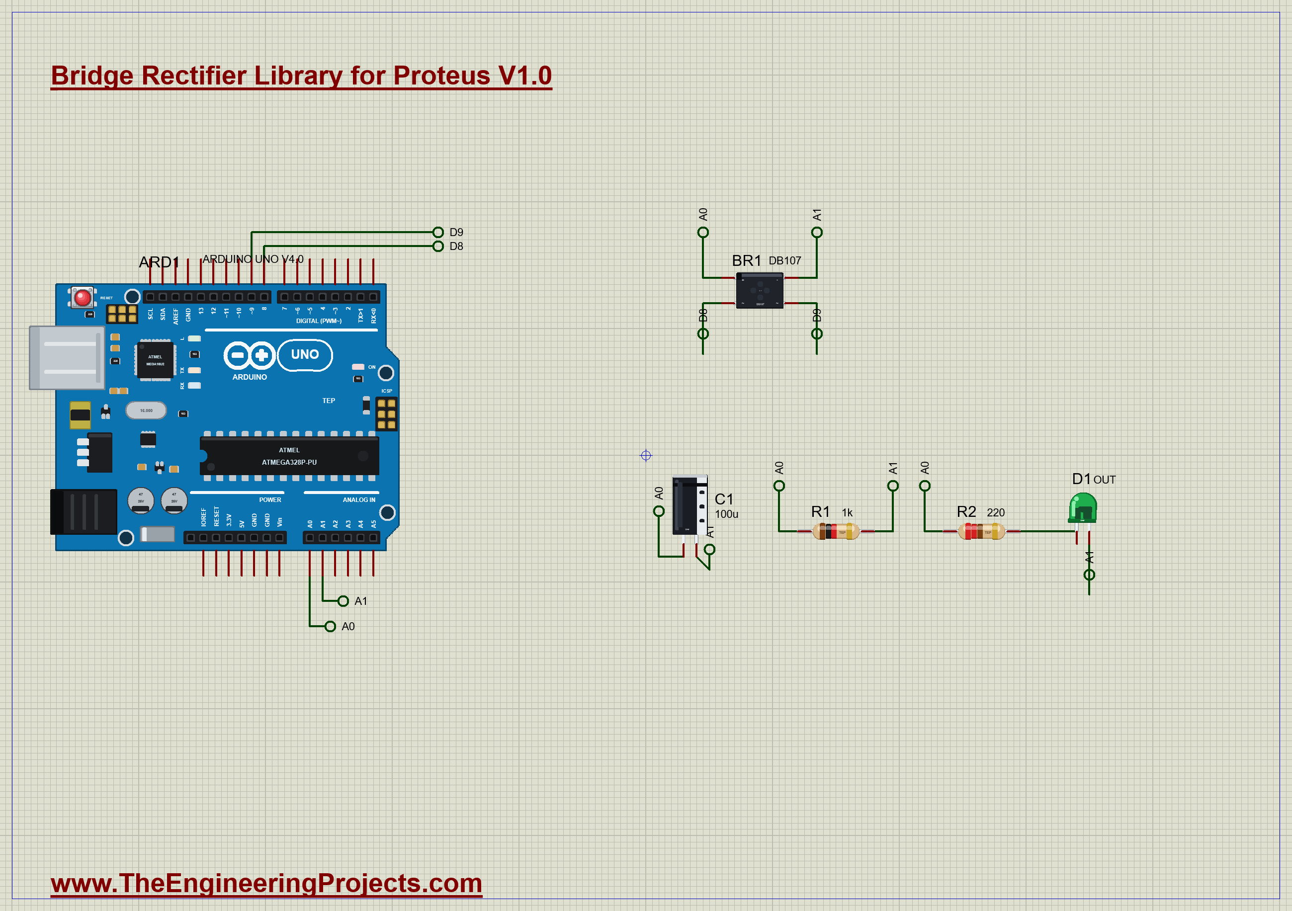
| Part | Connection | Job |
|---|---|---|
| BR1 | D8 and D9 on the ~ legs | the rectifier |
| A0 and A1 | BR1 + and BR1 - | read the output |
| C1, 100 uF | across + and - | smooths the output |
| R1, 1k | across + and - | the load |
| D1 and R2 | across + and - | a green LED |
Why Two Analog Pins?
Notice that the output is not tied to GND. It cannot be. The bridge's - leg sits one diode above whichever pin is LOW at that moment, and tying it to GND would short a diode. So the sketch reads the + leg and the - leg separately, and subtracts. This matters on a real board too: with a bridge, the AC side and the DC side do not share a ground unless you take great care.
Making the Square Wave
The sketch toggles the two pins together every 10 ms, which gives 50 Hz. Using micros() means nothing else has to stop while it waits:
  if (alternating && micros() - lastSwap >= HALF_CYCLE_US) {
    lastSwap += HALF_CYCLE_US;
    level = !level;
    drive(level);
  }
The Commands
| Type this | What happens |
|---|---|
| ac | the two pins swap, which makes 50 Hz |
| hold | they stop, with D8 HIGH and D9 LOW |
| swap | they stop, with D8 LOW and D9 HIGH: the supply is the other way round |
Run the Demo
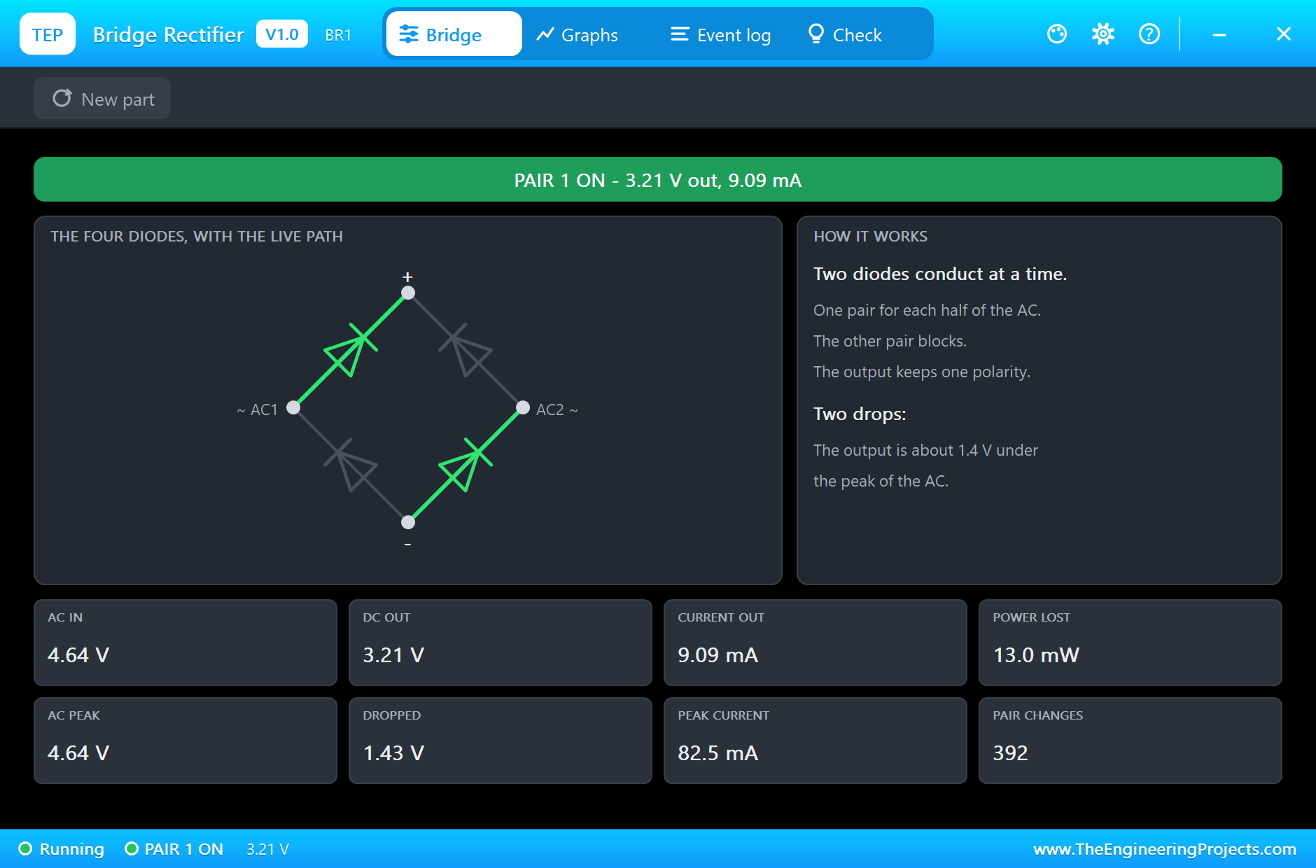
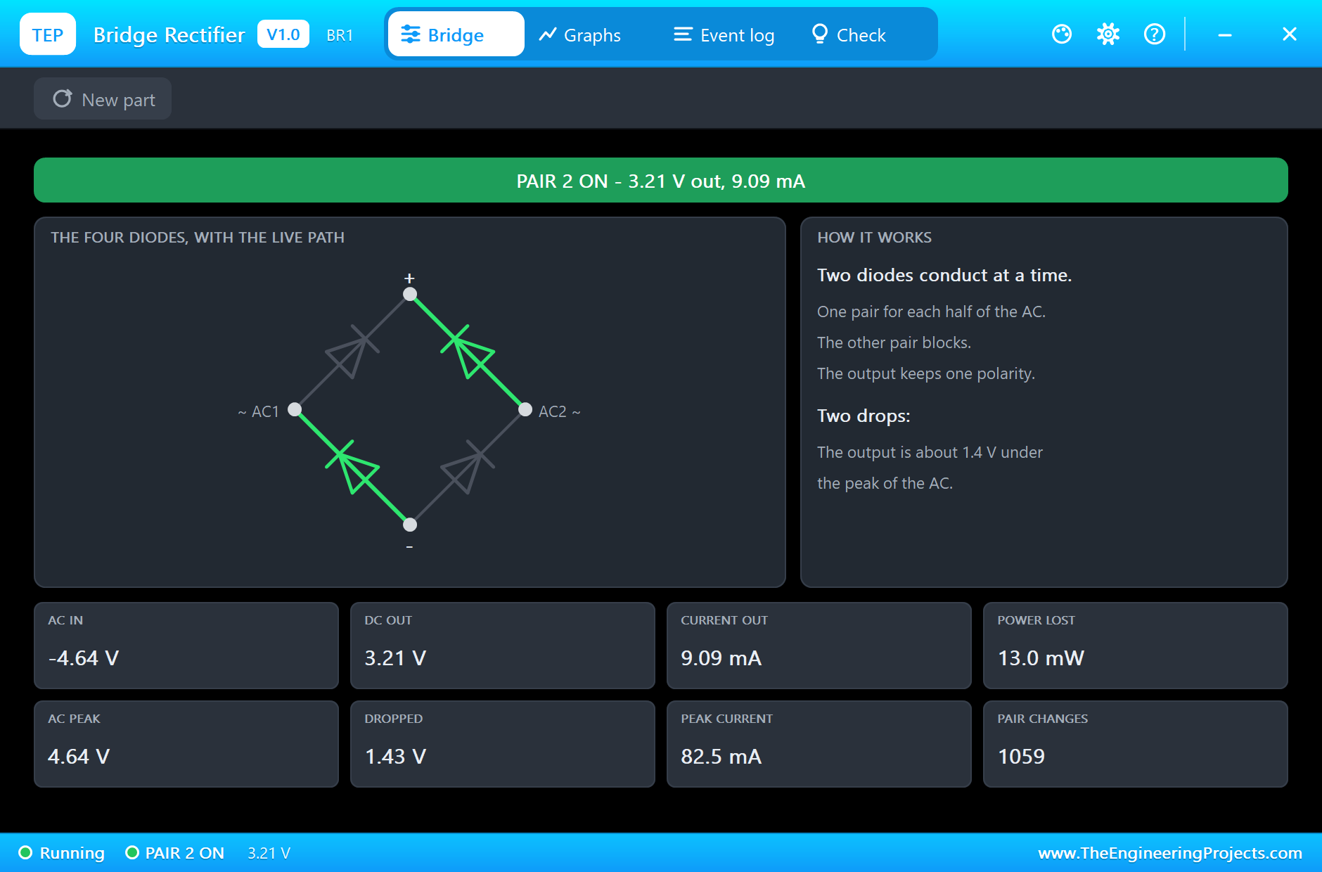
Press Run and the monitor opens. The green LED lights, and the small lamps on BR1 flicker as the pairs take turns. Click the block to open its pop-up. The diamond shows the two diodes carrying the current at this moment, lit in green:
Here is the complete circuit, truly running:
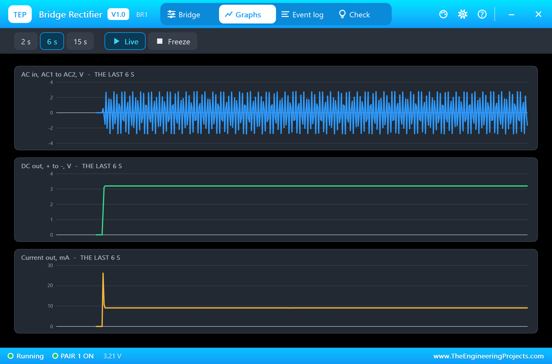
The Graphs tab is the best picture of a rectifier you will find. The blue trace is the AC going in, swinging both ways. The green trace is the DC coming out, steady and on one side of zero:
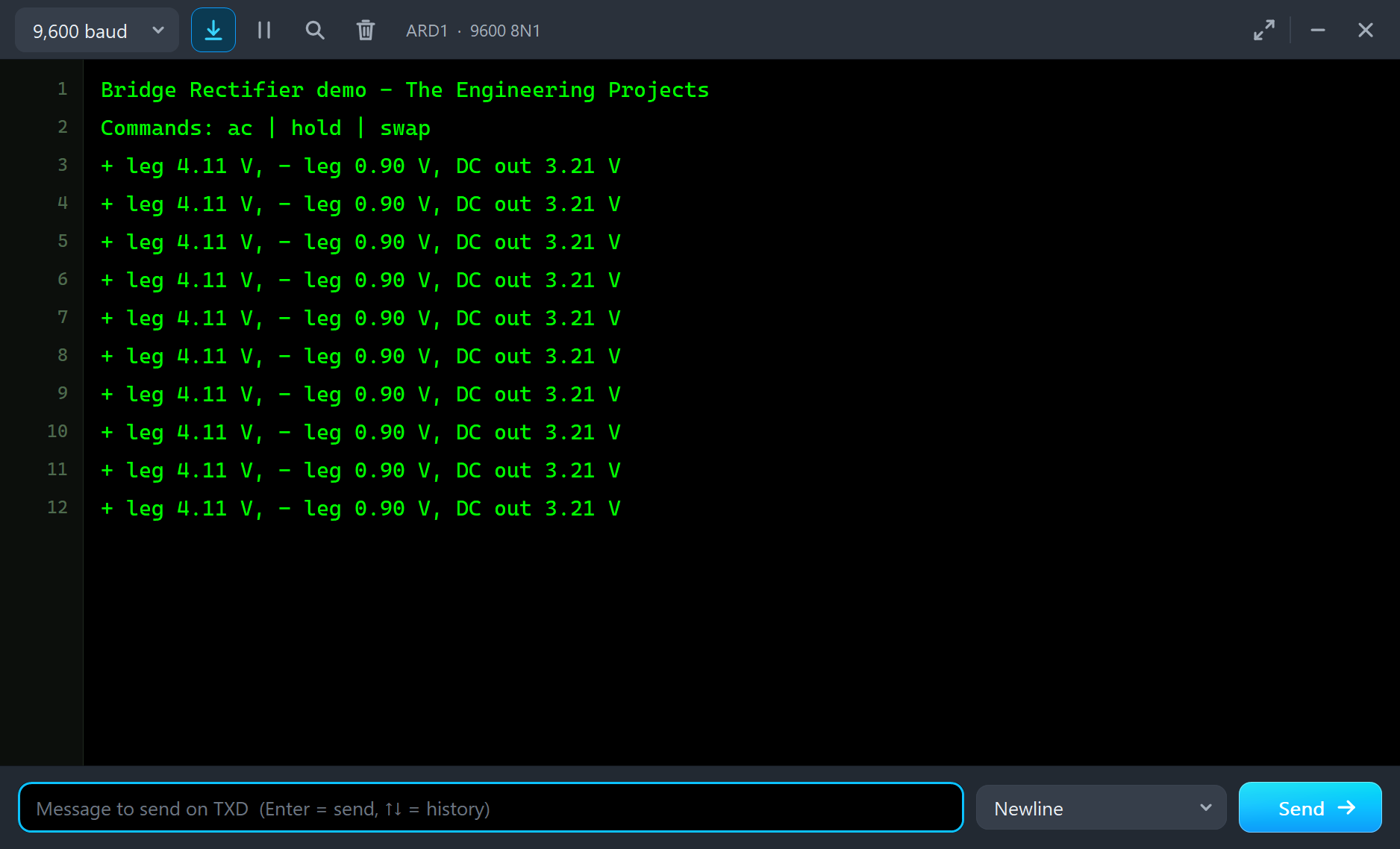
The monitor reads the two legs and the difference between them:
Turn the Supply Round
Now for the bridge's party trick. Type hold in the monitor. The wave stops with D8 HIGH, and one pair of diodes stays on. Then type swap. The supply is now the other way round. The other pair takes over, and the LED does not even blink:
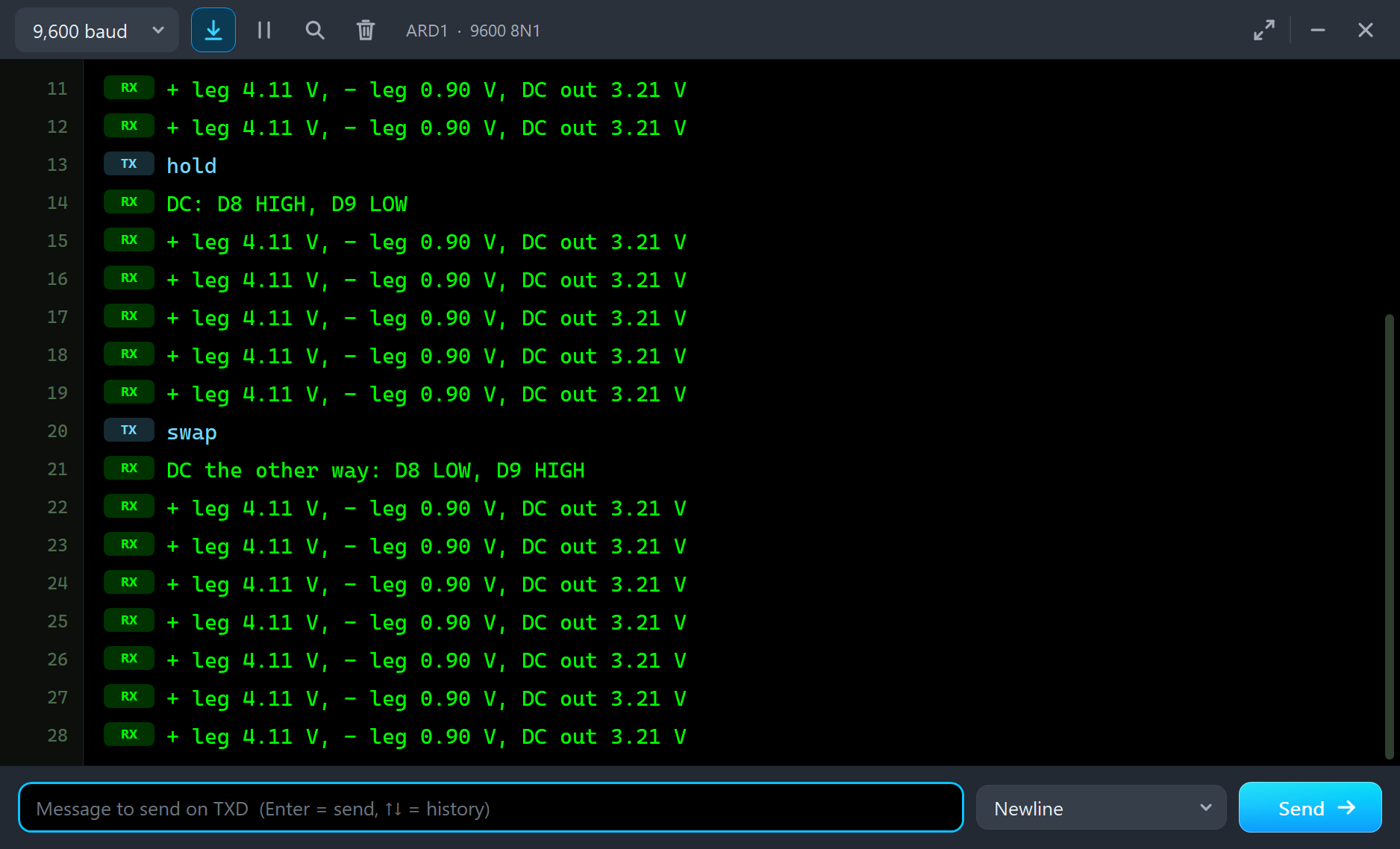
The numbers tell the story of the two drops. The + leg reads 4.11 V, not 5 V, as the first diode and the pin both take their share. The - leg reads 0.90 V, not 0 V, for the same reason on the way back. The difference, 3.21 V, is what the load really gets.
This makes a bridge a perfect reverse polarity protector. Many battery-powered gadgets and doorbells use one, so that you can connect the two wires either way round.
The Log and the Check Page
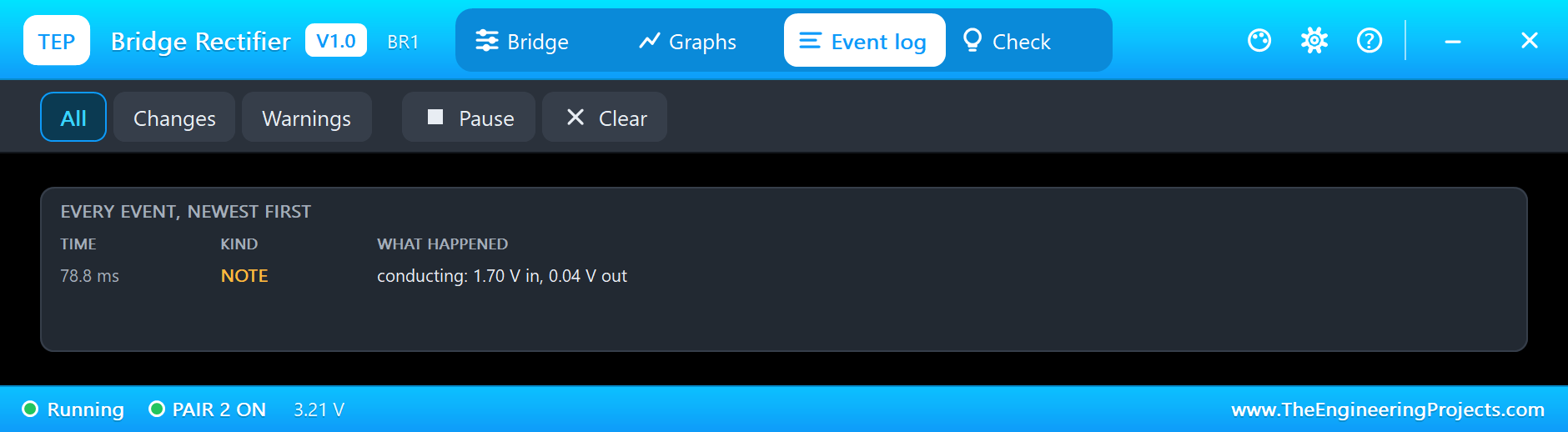
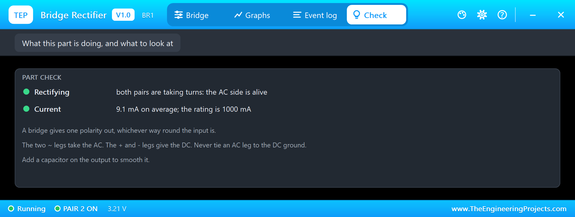
Type ac to start the wave again. The Event log keeps the record, and the Check page tells you whether both pairs are working:
Try It Yourself
- Remove C1, and watch the output drop to zero at every swap of the pins.
- Change the half cycle in the sketch to make 100 Hz, and see the ripple fall.
- Remove R1 and the LED, and see the output rise as the current falls.
- Tie the - leg to GND, and find out why that is a bad idea.
- Measure the two drops yourself, from the pop-up's numbers.
Ideas to Extend the Demo
- Add a 7805 regulator after the bridge, as a real power supply would.
- Build the same bridge from four 1N4007 diodes, and compare.
- Use four Schottky diodes, and see how much more voltage you keep.
- Protect a battery input against reversal, using a bridge.
Your Own Sketches
The demo sketch is in the zip file, and you can change it in the Arduino IDE. New to Arduino? Start with our Arduino Tutorial for Beginners. Export the compiled binary, and set the UNO's PROGRAM property to the new file. Our guide on How to get the HEX file from Arduino shows you where the file ends up.
Things to Know Before Using a Real Bridge
- Respect the mains: a bridge on the mains output is deadly, and it stays charged after power off. Use a transformer, and keep your hands away.
- Never tie an AC leg to the DC ground: that shorts a diode.
- Rate it for the peak: choose the voltage from the peak of your AC, not the RMS.
- Allow for the rush: a big capacitor pulls a large pulse at switch-on, and a small resistor or thermistor helps.
- Keep it cool: at higher currents, it needs a heat sink.
Troubleshooting
- No output: check the two ~ legs, and that the load is across + and -.
- The output is low: two diodes drop about 1.4 V in all, and that is normal.
- SHORTED: it was overcooked. Fix the circuit first, then press New part.
- The pop-up does not open: click the block while the simulation runs.
- The part is not simulated:
TEPBRIDGE.DLLis missing from MODELS and from the project folder.
Limitations of the Simulation
- The reverse recovery time and the capacitance of the junctions are left out.
- The drop does not change with temperature.
- A real bridge may fail with one diode open. Ours always fails short.
- Arduino is a name of Arduino; this library is not made or endorsed by Arduino or Labcenter.
- Tested in Proteus 8.5 in October 2026 (the demo as shipped). Proteus 7 is not supported.
So, that was all about the Bridge Rectifier Library for Proteus. I hope watching the two pairs take turns makes the famous diamond easy to remember. If you have any questions, ask in the comments and I will help you out. Till the next tutorial, take care and have fun!

Comments
0