


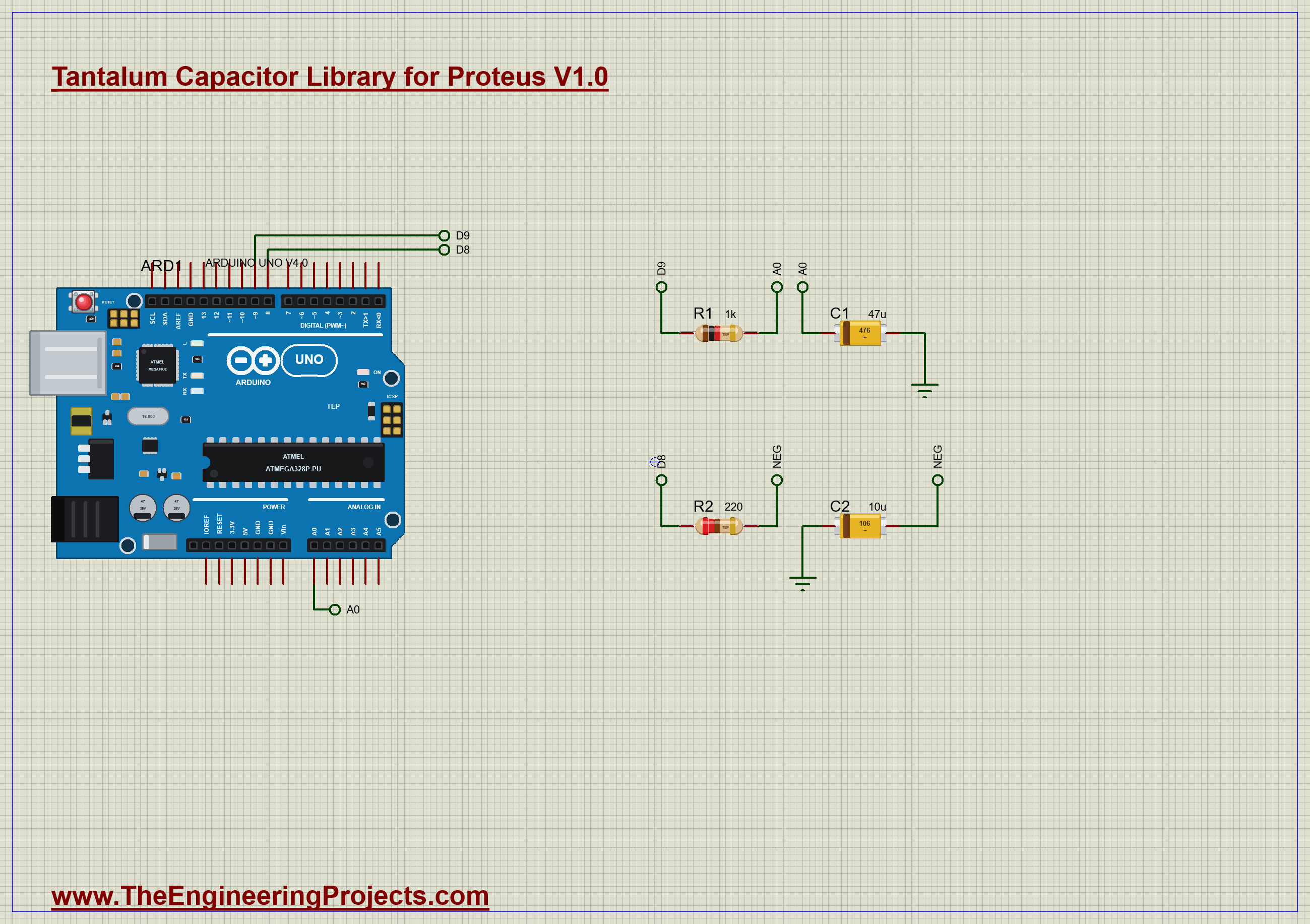
Tantalum Capacitor Library for Proteus: Yellow Chip, PWM Filter


Hello friends, I hope you all are doing great. Today, I am going to share the new Tantalum Capacitor Library for Proteus. The tantalum capacitor is the little yellow block you see on phones, laptops and good quality boards. It packs a lot of capacitance into a tiny space, it stays stable, and it has two surprises waiting for anyone who treats it like an ordinary electrolytic.
Tantalum Capacitor Library for Proteus
Latest version: V1.0 (November 2026, this tutorial)
Helping Tools
- Serial Monitor Advance: a serial terminal window for the UART of your board
- Serial Monitor Expert: the serial monitor with extra debugging tools
- LCD Library for Proteus V3.0: 16x2, 20x4 and I2C LCDs to show your readings
The first surprise is the mark on the case. On a tantalum, the band shows the plus end, the exact opposite of an electrolytic. The second is how it dies: it does not open quietly, it fails short. So we built a real-looking yellow chip that prints its own code and fails just like the real part. For the demo, an Arduino turns PWM into a smooth analog voltage, and then we kill a tantalum on purpose so that you never have to.
NOTICE: Our team has put a lot of effort into these small parts: the bodies, the animation and the pop-ups are all our own design, and you get them free. Your feedback is the fuel that keeps us going, so please tell us what you think in the comments below or in the Tantalum Capacitor board of our forum. And if our free libraries help you, you can buy us a coffee. So, let's get started with the Tantalum Capacitor Library for Proteus:
What is a Tantalum Capacitor?
A tantalum capacitor is a polarised capacitor built around tantalum, a rare and very stable metal. Its positive plate is a tiny pellet made from pressed tantalum powder, full of pores, which gives it a huge surface in a small space. A thin layer of tantalum oxide grows over that surface, and this oxide is the insulator. The negative plate is a solid material, usually manganese dioxide, that fills the pores. There is no liquid inside, so a tantalum does not dry out as an electrolytic does.
That design gives it a lot of capacitance for its size, and the value holds steady over temperature and over the years. It is more expensive than an aluminium electrolytic, so you find it where space is tight or where a stable part matters: phones, laptops, medical and military equipment, and the output of many voltage regulators.
| Feature | The real part | In the library |
|---|---|---|
| Size | case D, 7.3 x 4.3 mm | 306 x 180 thou, true scale |
| Value | 1 uF to hundreds of uF | 47 uF by default, any value |
| Voltage rating | 4 V to 50 V | 16 V by default |
| Polarity | the band marks the plus end | the same |
| Failure | it fails short | the same: it stays a short |
The Band Means Plus
This is the trap that catches almost everyone once. On an aluminium electrolytic, the stripe marks the negative leg. On a tantalum chip, the band marks the positive end. So if you move from one to the other out of habit, you will fit the part backwards. Always check the mark against the board and the datasheet.
The Three-Digit Code
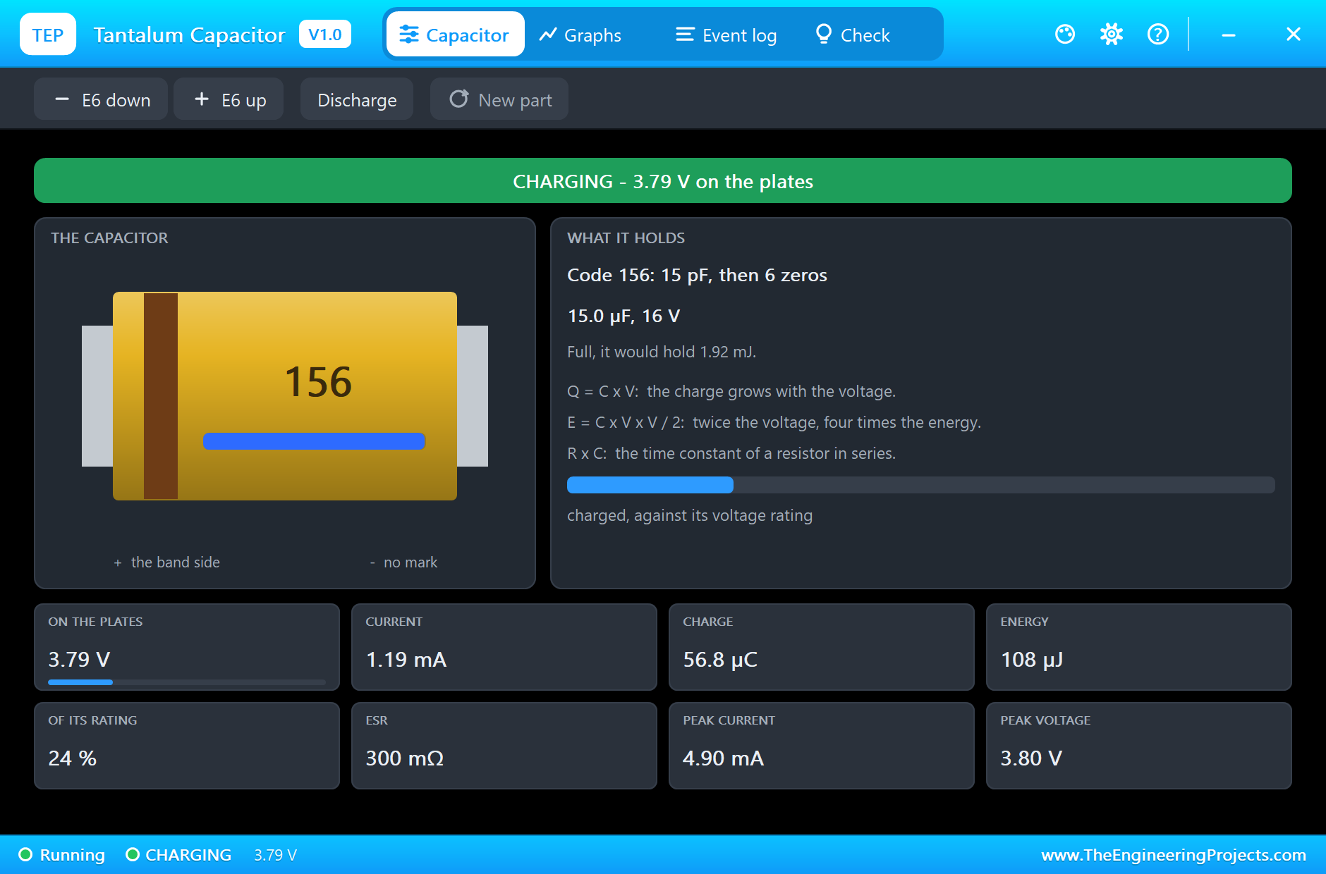
A tantalum chip uses the same three-digit code as a ceramic, which we covered in our Ceramic Capacitor Library for Proteus. The first two digits are the value, the third is the number of zeros, and the answer is in picofarads. So 476 is 47 followed by six zeros, which is 47,000,000 pF, or 47 uF. Likewise 106 is 10 uF. You will often see a voltage letter too: C means 16 V on many chips, and A means 10 V.
Case Sizes
Chip tantalums come in standard case sizes, and each maker uses the same letters. A larger case holds a higher value or a higher voltage. Our part is a case D, which is a very common size for 47 uF at 16 V:
| Case | Length x width | A typical part |
|---|---|---|
| A | 3.2 x 1.6 mm | 10 uF, 6.3 V |
| B | 3.5 x 2.8 mm | 22 uF, 10 V |
| C | 6.0 x 3.2 mm | 47 uF, 10 V |
| D | 7.3 x 4.3 mm | 47 uF, 16 V |
Which Capacitor Should I Use?
The three common families each have their place. Our Electrolytic Capacitor Library for Proteus covers the big cans and our ceramic library covers the small discs. Here is how a tantalum compares with them:
| Type | Values | Polarity | When it fails | Good for |
|---|---|---|---|---|
| Ceramic | pF to a few uF | none | cracks | fast decoupling |
| Tantalum | 1 uF to hundreds of uF | yes, band is plus | short | small, stable bulk storage |
| Electrolytic | 1 uF to thousands of uF | yes, stripe is minus | dries out or vents | big, cheap bulk storage |
Why Does a Tantalum Fail Short?
The oxide layer is incredibly thin. If a weak spot breaks down, or if the part is reversed, current rushes through that one tiny spot and heats it. In a part with manganese dioxide, that heat can start a reaction that makes things worse, and with a strong supply behind it the capacitor can even catch fire. This is why designers run a tantalum at half its rated voltage or less. It is also why a dead tantalum is easy to find on a real board: it is often a dead short across the supply, and it may be the hottest part there.
Tantalums and Voltage Regulators
Many small boards use a tantalum on the output of a low-dropout regulator, such as the 3.3 V regulator on a sensor module. The reason is a little surprising: these regulators need some series resistance in the capacitor to stay stable. A tantalum has just the right amount. A modern ceramic has so little ESR that an older regulator may start to oscillate, and the output turns into a noisy mess. So always read the capacitor section of a regulator datasheet.
There is also a human side to this part. Much of the ore for tantalum is mined in a few parts of the world, and some of it has funded armed conflict. For that reason, tantalum is listed as a conflict mineral, and large companies now have to show where theirs comes from.
Features of the Tantalum Capacitor Library for Proteus
- The real look, at true scale: the yellow chip, the brown band, two metal ends, with our small TEP signature.
- It prints its own code: 15 values from 1 uF to 220 uF, and the digits on the chip follow the value.
- A live charge bar: a small blue bar on the chip follows the voltage at Run.
- A true capacitor: a capacitance behind an ESR in the analog simulator, so it filters and charges on the real curves.
- It fails like the real thing: reverse it and it heats, chars and stays a short across your circuit.
- A pop-up for every part: click it at Run for the code, the charge, eight live values, graphs, an event log and a check page.
- Live changes: step the value through the E6 series while it runs, and see the effect at once.
- A complete package: about 1.5 MB with the library, our Arduino UNO V4.0, the demo's resistors and the demo, without the source code of the models.
The Tantalum Capacitor in Proteus
The device is CAPTANTALUMTEP in TEPTANTALUM.LIB, under Capacitors, Tantalum SMD, with the prefix C and the model TEPTANTALUM.DLL. Search CAPTANTALUM in Pick Devices. The + pin is on the band side, and the other pin is -.
The Properties
| Property | What it does |
|---|---|
| Capacitance | the value: 47u, 10u or 4u7; a bare number is in uF |
| Voltage rating, V | the working voltage, 16 by default |
| Series resistance (ESR), ohm | 0.3 ohm by default |
| Printed code while stopped | the digits shown on the stopped sheet |
The chip shows its code while the simulation is stopped, because the code is one of 15 ready-drawn looks of the part. At Run, the model reads the Capacitance box and sets the code to match.
Download Tantalum Capacitor Library for Proteus
Click the button below to download Tantalum-Capacitor-Library-for-Proteus-v1.0.zip (about 1.5 MB, without the source code of the models):
Tantalum Capacitor Library for Proteus V1.0- README.txt: installation, the demo, the properties, troubleshooting and the limits.
- Proteus Library Files:
TEPTANTALUM.LIB,TEPRESISTOR.LIBand ourArduinoV4TEP.LIB. - Proteus Model Files:
TEPTANTALUM.DLL,TEPRESISTOR.DLLandTEPARDUINO.DLL. - Arduino Code: the demo sketch.
- Proteus Simulation: the demo project, its HEX file and copies of the DLLs.
No Proteus yet? Read How to Download and Install Proteus 7 and 8. New to libraries? Follow How to Install a New Library in Proteus.
How to Install Tantalum Capacitor Library for Proteus
- Close Proteus and extract the whole zip file, for example to your Desktop.
- Copy the files from Proteus Library Files into the LIBRARY folder of Proteus.
- Copy the files from Proteus Model Files into the MODELS folder.
- Delete
TEPTANTALUM.IDXfrom the LIBRARY folder if it is there. - Start Proteus, press P and search for CAPTANTALUM.
Demo: Turning PWM into a Real Voltage
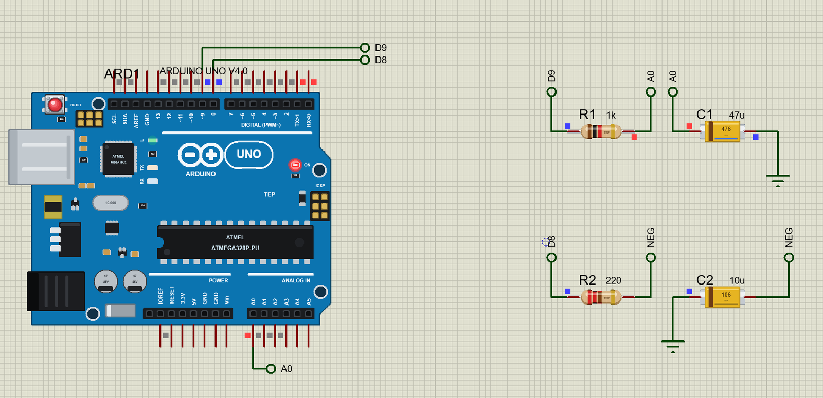
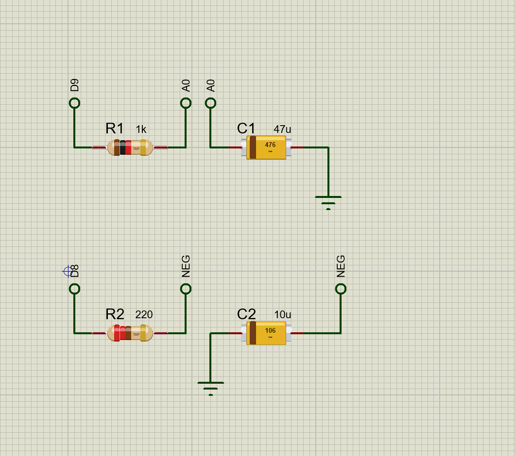
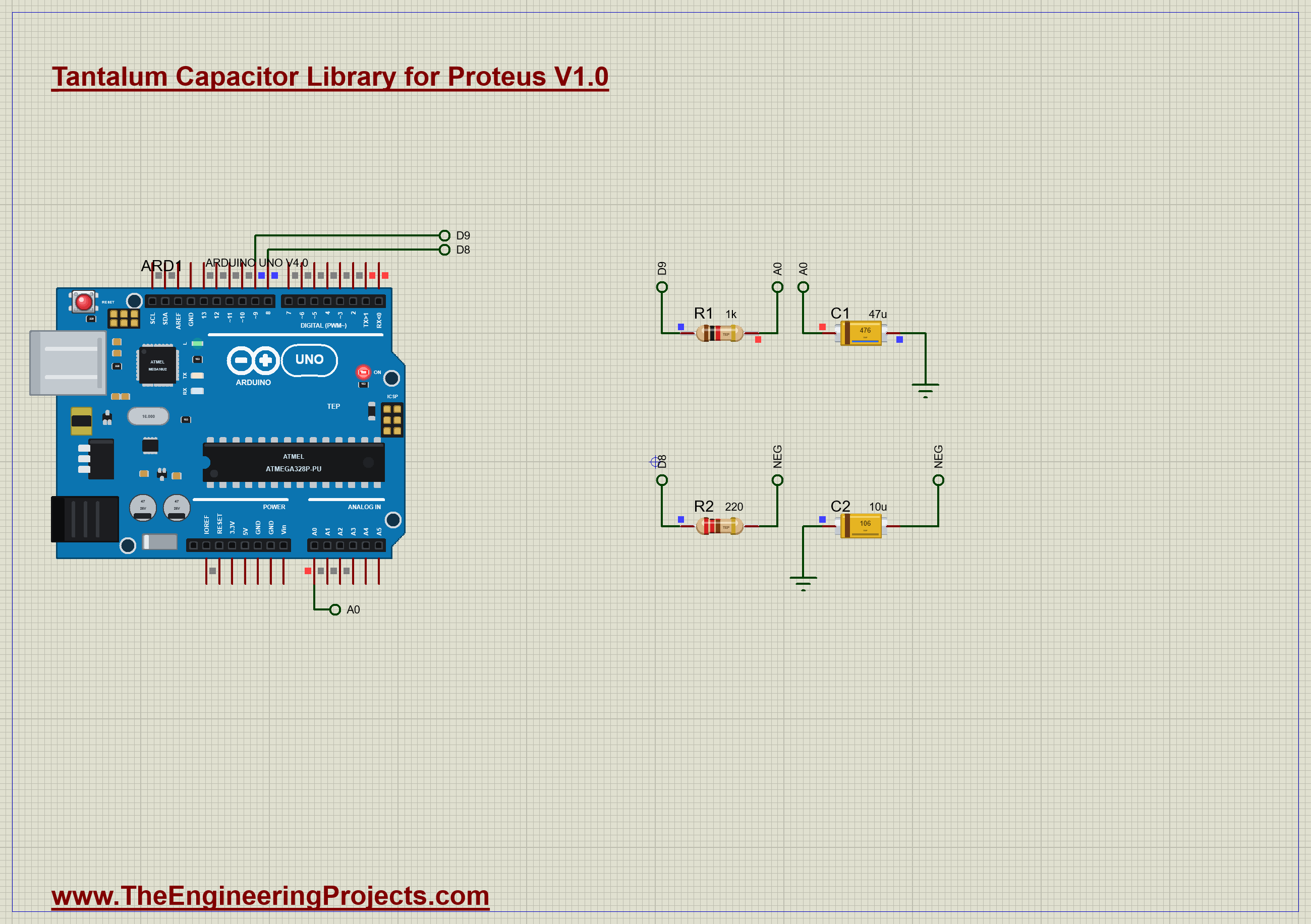
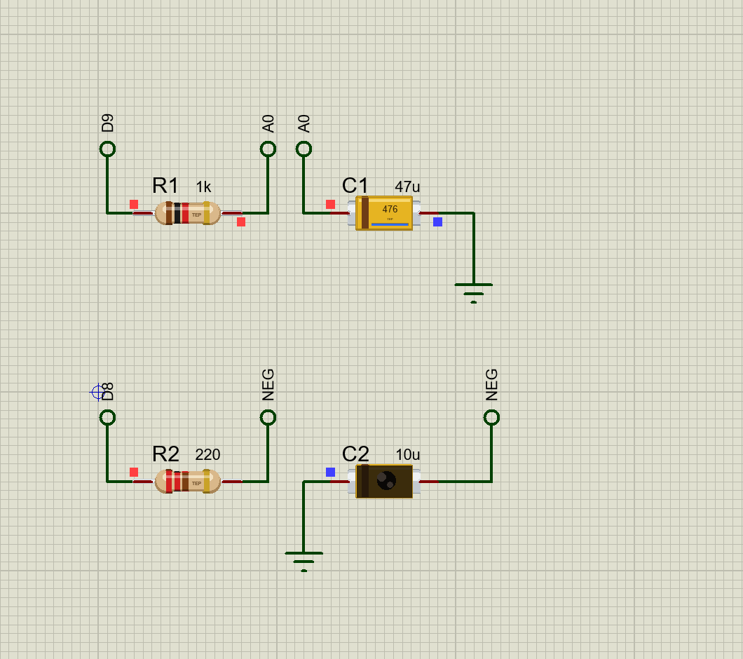
An Arduino UNO has no true analog output. analogWrite() only switches a pin on and off very quickly, about 490 times a second on D9. But a resistor and a capacitor can smooth those pulses into a steady voltage, which is called a low-pass filter. That is the first half of our demo. R1 and C1 make the filter, and A0 reads the result. R2 and C2 are the warning: C2 stands backwards, ready for the moment we send it 5 V. Open Tantalum-PWM-Filter-ArduinoUnoV4.pdsprj. It runs on our Arduino UNO Library for Proteus V4.0, with its built-in monitor, the same window as our TEP Serial Monitor Advance for Proteus. The resistors are from our Resistor Library for Proteus.
| Part | Connection | Job |
|---|---|---|
| R1, 1k | D9 to A0 | with C1, smooths the PWM |
| C1, 47 uF | A0 to GND, + on A0 | the filter |
| R2, 220 ohm | D8 to C2 | limits the current |
| C2, 10 uF | - on R2, + on GND | the reversed part |
How the Filter Works
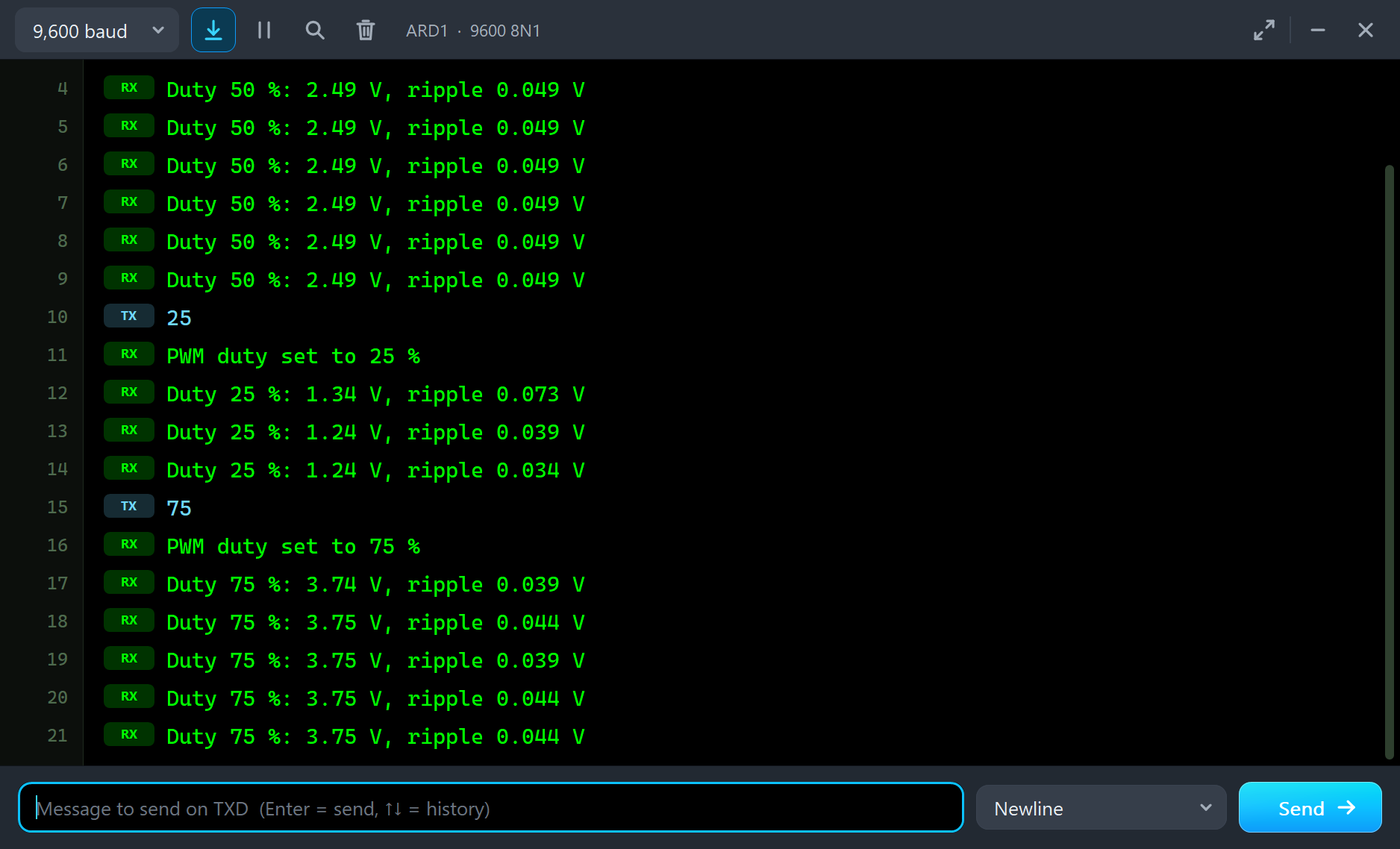
When the pin is HIGH, C1 charges a little through R1. When the pin is LOW, C1 gives a little back. If R x C is much longer than one cycle of the PWM, the voltage barely moves in each cycle, and it settles at the average of the pulses. Here R x C is 1,000 x 0.000047, or 47 ms, against a PWM cycle of about 2 ms. So a duty of 50 % gives half of 5 V, and a duty of 75 % gives three quarters.
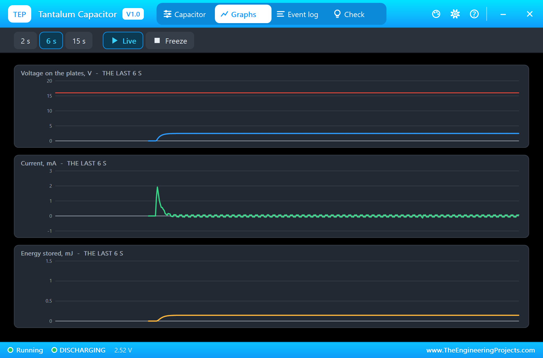
A little of the pulse still gets through, and this is called the ripple. A simple formula predicts it: ripple = V x D x (1 - D) x T / (R x C), where D is the duty and T is the time of one cycle. It is largest at 50 % duty, and it shrinks as R x C grows. You pay for that with speed, because the filter takes about five time constants, some 235 ms, to settle at a new value.
Measuring the Ripple
The sketch takes 64 quick readings of A0 over about 20 ms, which covers several PWM cycles. It keeps the sum, the lowest and the highest. The sum gives the average, and the gap between the highest and the lowest gives the ripple:
  for (int k = 0; k < SAMPLES; k++) {
    int a = analogRead(SENSE_PIN);
    sum += a;
    low = min(low, a);
    high = max(high, a);
    delayMicroseconds(200);
  }
The Commands
| Type this | What happens |
|---|---|
| 0 to 100 | sets the PWM duty in percent |
| reverse | D8 goes HIGH: 5 V across C2 the wrong way |
| safe | D8 goes LOW again |
Run the Demo
Press Run and the monitor opens. The sketch starts at 50 % duty, and within a moment C1 settles near 2.5 V. Click the chip to open its pop-up. The code is explained at the top of the right-hand card:
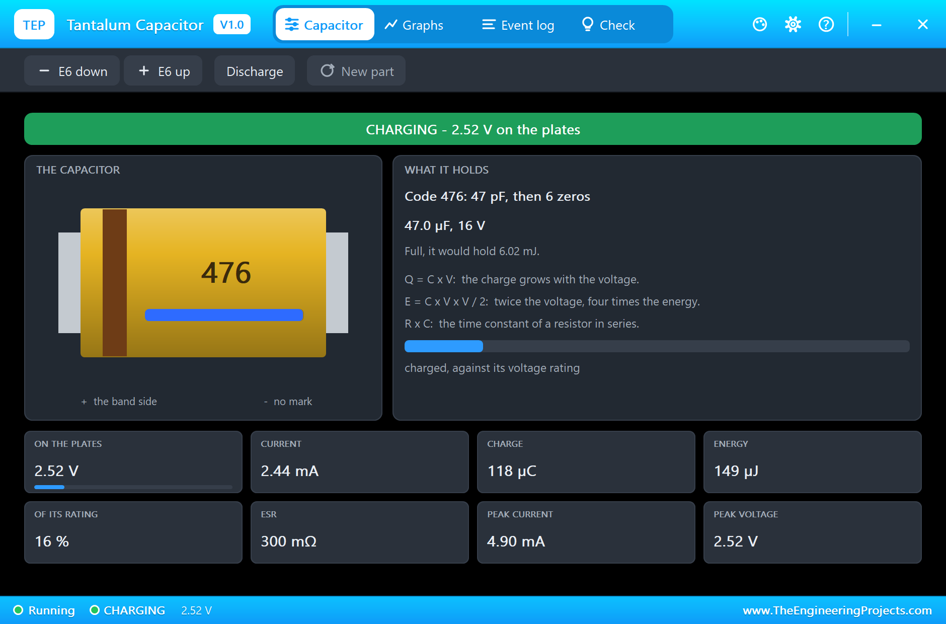
Here is the complete circuit, truly running, with the blue bars on the chips showing the charge:
The Graphs tab shows how quickly the filter settles after Run:
Change the Duty
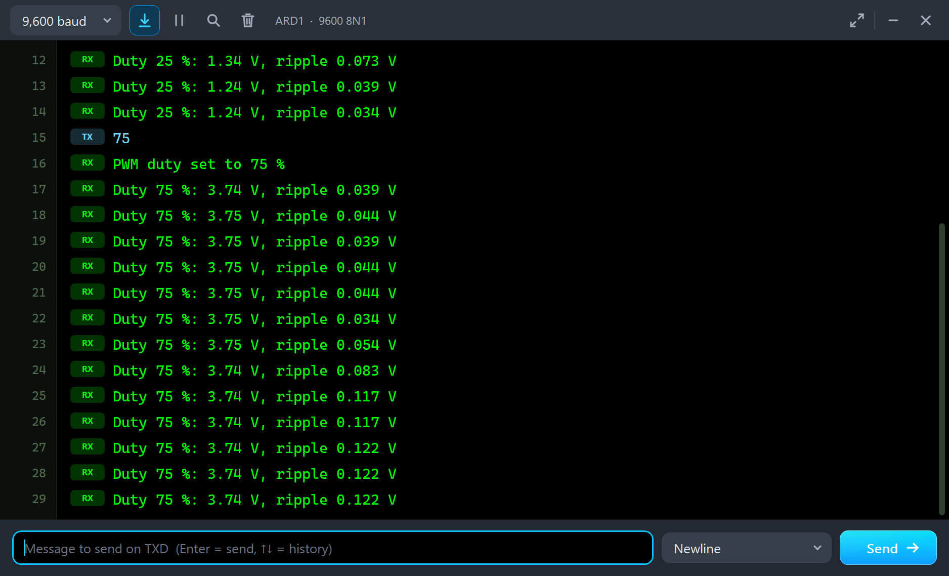
Type 25 in the monitor and press Send, then type 75. The voltage follows, at 1.24 V and then 3.75 V:
Now Shrink the Capacitor
Keep the duty at 75 %, click C1 and press E6 down three times. The value steps from 47 uF to 33, 22 and then 15 uF, and the code on the chip changes with it. The voltage stays the same, but the ripple grows. The numbers follow the formula closely:
| C1 | The formula | The monitor |
|---|---|---|
| 47 uF | 0.041 V | 0.039 to 0.044 V |
| 33 uF | 0.058 V | 0.054 V |
| 22 uF | 0.087 V | 0.083 V |
| 15 uF | 0.128 V | 0.117 to 0.122 V |
Now the Warning
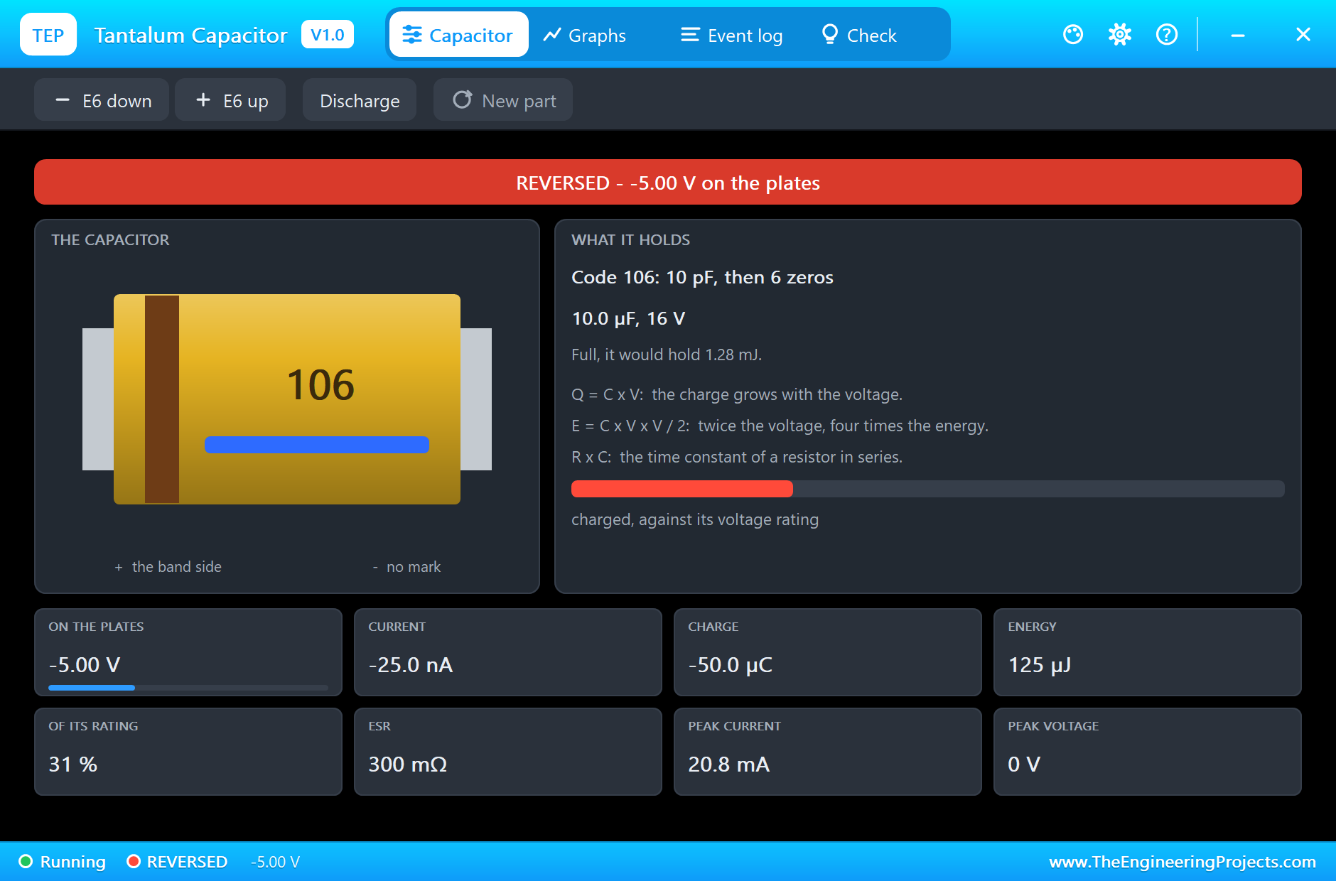
Press E6 up three times to get back to 47 uF, then type reverse. D8 goes HIGH, and C2 sees 5 V the wrong way round. The banner turns red at once:
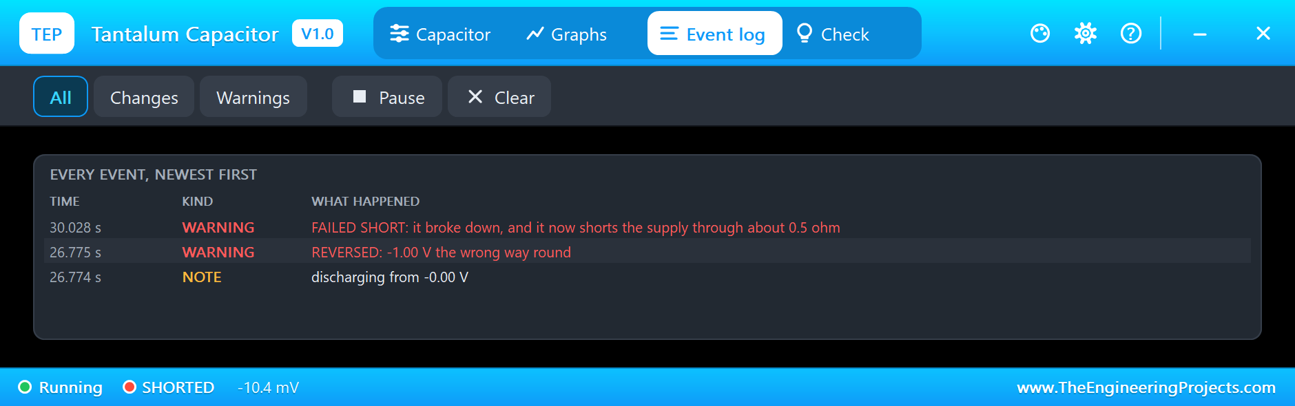
A few seconds later, the part gives up. The chip chars, and the pop-up reports the failure. Look closely at what it says. An electrolytic opens when it bursts, so the circuit simply stops working. A tantalum becomes a short, so now the pin is driving a current into almost nothing, limited only by R2:
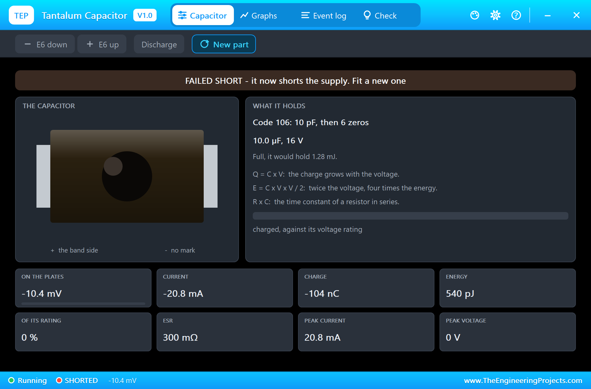
Without R2, that short would sit straight across the pin. On a real power rail with no resistor at all, it could pull down the whole supply, and this is how a single tiny part can stop a complete board from starting.
The Log and the Check Page
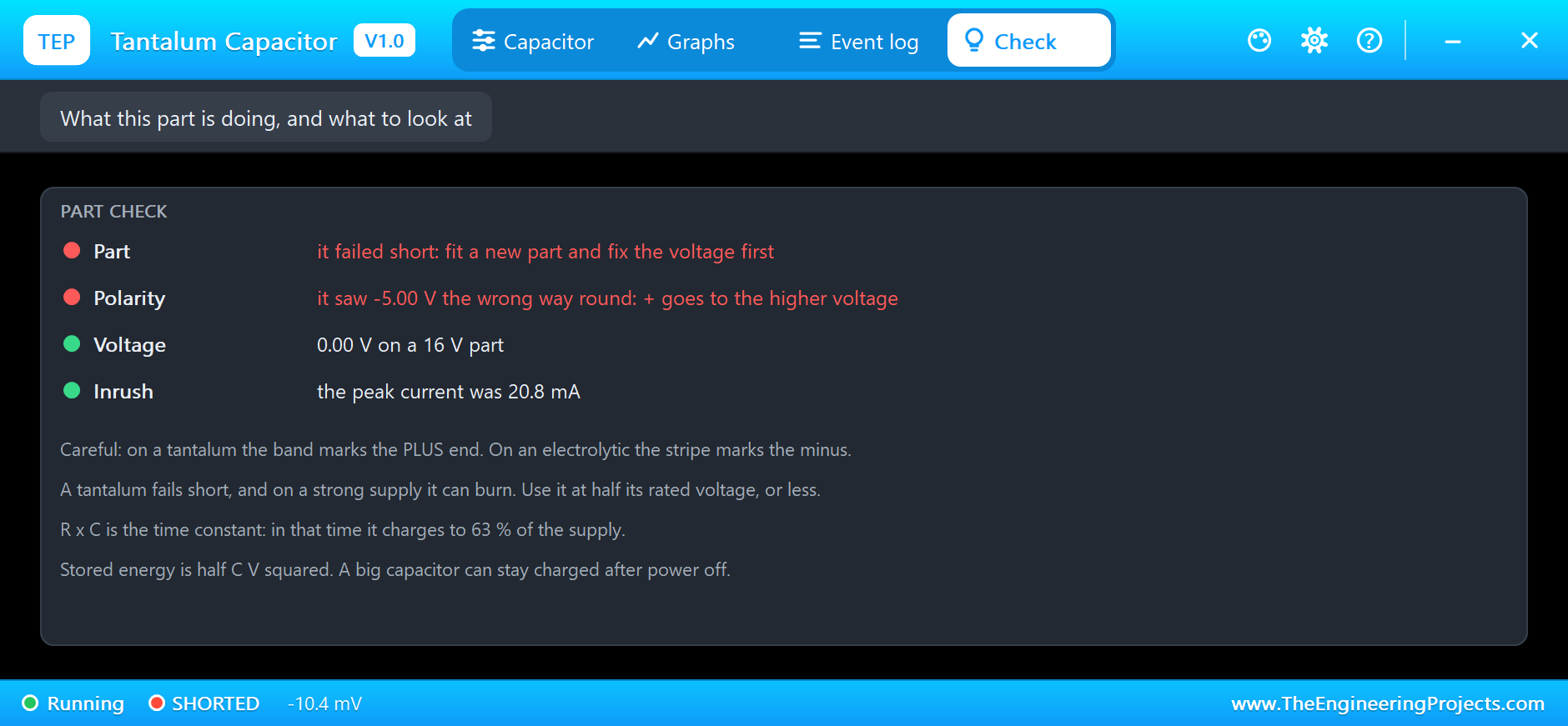
The Event log keeps the whole story, and the Check page tells you what went wrong and what to do about it:
Type safe to take the voltage away, and press New part on the pop-up to fit a fresh chip.
Try It Yourself
- Set the duty to 50 %, and check that the ripple is at its largest there.
- Change R1 to 10k, and see the ripple fall to a tenth, with a much slower response.
- Change the duty quickly in the sketch, and measure how long the filter takes to settle.
- Set the voltage rating of C2 to 4 V, turn it the right way round, and see what 5 V does.
- Add a second filter stage, and see how much further the ripple falls.
Ideas to Extend the Demo
- Drive a small audio stage with the filtered PWM and hear a smooth tone.
- Use the voltage to set the brightness of an LED through a transistor.
- Make a simple digital to analog converter that follows a table of values.
- Compare the filter with a real digital to analog converter chip.
Your Own Sketches
The demo sketch is in the zip file, and you can change it in the Arduino IDE. New to Arduino? Start with our Arduino Tutorial for Beginners. Export the compiled binary, and set the UNO's PROGRAM property to the new file. Our guide on How to get the HEX file from Arduino shows you where the file ends up.
Things to Know Before Using a Real Tantalum
- Check the band: it marks the plus end, the opposite of an electrolytic.
- Derate it: keep the voltage at half the rating or less, especially on a low-resistance supply.
- Limit the surge: a big rush of current at switch-on is the classic killer. Some resistance in series helps a lot.
- Keep your face away: a tantalum that fails on a strong supply can burn fiercely.
- Regulators care about ESR: many older low-dropout regulators are only stable with a certain ESR on their output, so the datasheet may ask for a tantalum.
Troubleshooting
- The code does not match the value: press Run once. The model sets the code to the nearest E6 value.
- SHORTED: it was reversed or over voltage. Fix the circuit first, then press New part.
- A0 reads a wide ripple: R x C is too small for the PWM.
- The pop-up does not open: click the chip while the simulation runs.
- The part is not simulated:
TEPTANTALUM.DLLis missing from MODELS and from the project folder.
Limitations of the Simulation
- The value does not change with temperature, and the inductance of the part is left out.
- A real part fails in its own time. Ours follows a simple heating rule, so the seconds are not a prediction.
- The flame of a real failure is left out, and so is the self-healing of polymer types.
- Arduino is a name of Arduino; this library is not made or endorsed by Arduino or Labcenter.
- Tested in Proteus 8.5 in October 2026 (the demo as shipped). Proteus 7 is not supported.
So, that was all about the Tantalum Capacitor Library for Proteus. I hope you remember which way the band goes, and that the only tantalum you ever burn is on your screen. If you have any questions, ask in the comments and I will help you out. Till the next tutorial, take care and have fun!

Comments
0