


Relay Module Library for Proteus V1.0: 1, 2, 4 and 8 Channel 5V


Hello friends, I hope you all are doing great. Today, I am going to share the new Relay Module Library for Proteus V1.0. The blue 5 V relay module is in almost every Arduino kit: one, two, four or eight SONGLE relays on a board, with optocouplers, LEDs and screw terminals. It lets a small Arduino pin switch a lamp, a fan, a pump, a solenoid lock or a motor, with the load completely separated from the Arduino. Home automation, plant watering, garage doors and smart sockets all start with this module. Now you can build and test them in Proteus.
Behind the parts sits our own model, not a symbol on top of a Proteus relay. Each input works like the real one, active LOW through an LED and a PC817 optocoupler. Each relay has a coil that takes time to build up its current, an armature that picks up and drops out at the levels of the datasheet, and contacts that break before they make and bounce. The contacts are real circuit elements, so a lamp, an LED or an Arduino input on them sees the real switching. You get eight devices: the 1, 2, 4 and 8-channel modules, each as a Simple device with a live STATUS panel and as an Advance device with a pop-up window and three test tools. The demo runs on our Arduino UNO V4.0.
NOTICE: a relay library is easy to fake: flip a switch the moment the pin changes. We wanted more. Our relays need about 7 ms to switch, ignore pulses that are too short, cannot follow PWM, stop working when the JD-VCC jumper is pulled and bounce on every closing, just like the modules on your desk. It took our team a lot of hard work. Your feedback is the fuel that keeps us going, so please tell us what you think in the comments below or in the Motor Driver board of our forum. And if our free libraries help you, you can buy us a coffee. So, let's get started with the Relay Module Library for Proteus V1.0:
What is a Relay Module?
A relay is a switch moved by an electromagnet. A current through its coil pulls a metal armature, and the armature moves a contact from one terminal to another. Because the coil and the contacts are not connected, a 5 V coil can switch 230 V AC or 30 V DC on its contacts. The relay module adds everything an Arduino needs around the relay: a driver transistor for the coil current, a flyback diode, an optocoupler to separate the input, the LEDs and the screw terminals.
| The 5V relay module (the model) | |
|---|---|
| Relays | 1, 2, 4 or 8 SONGLE SRD-05VDC-SL-C, 10 A at 250 VAC or 30 VDC |
| Inputs | IN or IN1 - IN8, active LOW: LOW = the relay ON, HIGH or open = OFF |
| Supply | VCC 5 V for the inputs; JD-VCC for the coils (2, 4, 8 channels), the jumper ties it to VCC |
| Coil | 70 ohm, about 70 mA at 5 V, with a flyback diode on the board |
| Switching | operate about 7 ms, release about 5 ms (with the diode), break before make, bounce on the make |
| Contacts | COM, NO (normally open) and NC (normally closed) on a screw terminal per relay |
| On the board | PWR LED, an IN LED per channel, PC817 optocouplers, driver transistors, flyback diodes |
| Devices in this library | RELAY1TEP, RELAY2TEP, RELAY4TEP, RELAY8TEP (Simple) and RELAY1ADVTEP to RELAY8ADVTEP (Advance) |
How the Relay Module Works
Each channel starts at the input pin. When the Arduino pulls IN LOW, a current flows from VCC through the red IN LED and the LED inside the PC817 optocoupler into the pin. The light inside the optocoupler switches its transistor, and that switches the driver transistor of the coil. That is why the modules are active LOW: LOW means ON. A HIGH or an open pin means OFF, because no current flows through the LEDs. The two LEDs need about 3 V, and the optocoupler needs about 3.5 V on VCC before it switches reliably.
The coil does not get its full current at once. It has a resistance of 70 ohm and an inductance of about 0.21 H, so its current rises with a time constant of 3 ms. The armature picks up when the current reaches 75 percent of its rated value, 53.6 mA, and drops out when it falls below 10 percent, 7.1 mA. Then the armature still has to travel. The NC contact breaks first, and the NO contact makes about 2 ms later. This is break before make: COM never touches NO and NC at the same time. When NO makes, the contact bounces open and closed a few times within about half a millisecond. All together, a relay switches ON about 7 ms after its input goes LOW and OFF about 5 ms after it goes HIGH.
VCC, JD-VCC and the Jumper
The 2, 4 and 8-channel modules have a second supply pin, JD-VCC, for the relay coils. A yellow jumper connects it to VCC, so with the jumper on, everything runs from the Arduino's 5 V. Each coil takes about 70 mA, so four relays already need 280 mA. For more relays, or for full isolation, you remove the jumper and feed JD-VCC from a separate 5 V supply. Then VCC carries only the few milliamps of the LEDs and the optocouplers. The 1-channel module has no JD-VCC: its coil draws from VCC.
What's New in Relay Module Library for Proteus V1.0
- The real modules: the blue PCB with the input header, the JD-VCC block with its yellow jumper, the PWR LED, per channel the IN LED, the PC817, the transistor, the diode, the SONGLE relay with its ratings and the blue NO, COM and NC screw terminal.
- Four sizes, two styles: 1, 2, 4 and 8 channels, each as a Simple and an Advance device.
- A real relay model: the active LOW input with its optocoupler, the coil current with its time constant, pick-up and drop-out, the armature travel, break before make and contact bounce.
- Real contacts: COM to NO and COM to NC are 50 mohm when closed and open otherwise, switched at their exact times, so any part on the contacts sees the real switching.
- A clickable JD-VCC jumper: pull it while the simulation runs and the relays drop out, just like on a real board.
- Mistake detection: PWM on an input, pulses too short to switch, the start-up click, VCC too low for the optocoupler, no supply on JD-VCC, too much coil current for a USB port, a contact above 10 A, chatter.
- Three test tools on the Advance devices: Inputs, Power and Contacts.
- A two-node demo on our Arduino UNO V4.0, which reads the bounce of a contact back and makes every mistake on command.
- A compact package: about 1.33 MB, without the C++ source code of the model.
Eight Devices: Four Sizes, Simple and Advance
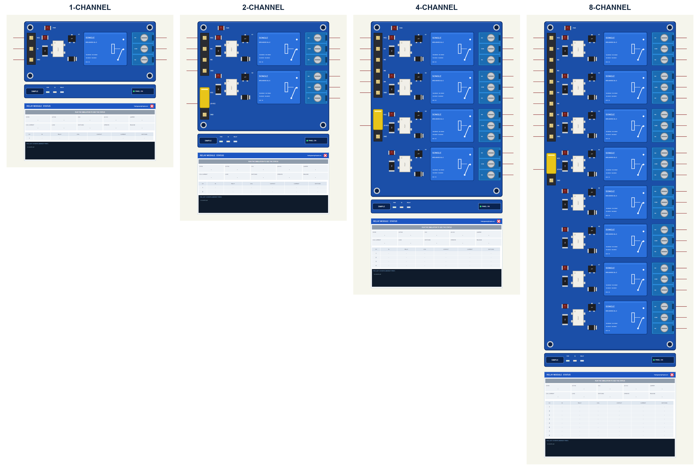
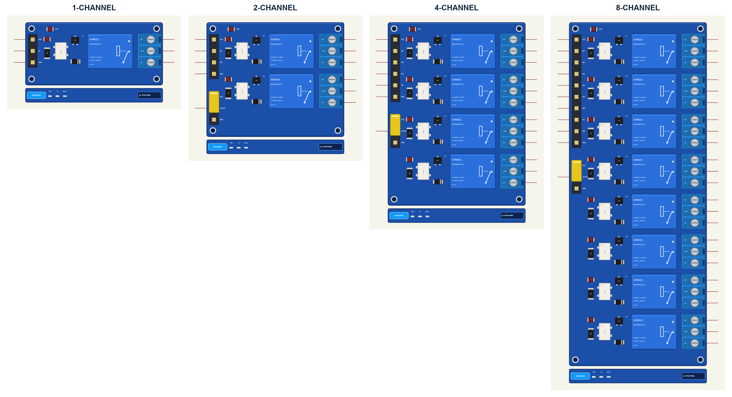
The boards are drawn with their relays one under the other: a real module turned by 90 degrees, with the input header on the left and the screw terminals on the right, so the wires to the Arduino and to the loads stay short and tidy. The 1-channel board has the pins VCC, IN and GND on its header; the larger boards have VCC, IN1 to INn and GND, plus the JD-VCC pin at the yellow jumper. On the right, each relay has its NO, COM and NC pins.
| Simple | Advance | |
|---|---|---|
| Devices | RELAY1TEP, RELAY2TEP, RELAY4TEP, RELAY8TEP | RELAY1ADVTEP, RELAY2ADVTEP, RELAY4ADVTEP, RELAY8ADVTEP |
| On the schematic | The board, its strip and the STATUS panel | The board and its strip |
| Status | Banner, 10 readouts, a row per relay, the last 4 events | A pop-up: Board, Event log, Tests |
| Interaction | PANEL button, the JD-VCC jumper | OPEN PANEL button, the JD-VCC jumper |
Download Relay Module Library for Proteus
Click the button below to download Relay-Module-Library-for-Proteus-v1.0.zip (about 1.33 MB, without the C++ source code of the model):
Relay Module Library for Proteus V1.0: 1, 2, 4 and 8 Channel 5V- README.txt: the devices, installation, the demo, wiring, the test tools and real hardware.
- Proteus Library Files:
TEPRELAY.LIBandArduinoV4TEP.LIBfrom our Arduino Library for Proteus V4.0. - Proteus Model Files:
TEPRELAY.DLLandTEPARDUINO.DLL. - Proteus Simulation:
Relay-Module-ArduinoUnoV4.pdsprj,Relay_Demo.hexand copies of the two DLLs. - Arduino Code:
Relay_Demo.ino. It needs no library, only the Arduino core.
No Proteus yet? Read How to Download and Install Proteus 7 and 8. New to libraries? Follow How to Install a New Library in Proteus.
How to Install Relay Module Library for Proteus
- Close Proteus and extract the whole zip file, for example to your Desktop.
- Copy the two files from Proteus Library Files into the LIBRARY folder of Proteus (usually
C:\Program Files (x86)\Labcenter Electronics\Proteus 8 Professional\LIBRARY). - Copy
TEPRELAY.DLLandTEPARDUINO.DLLfrom Proteus Model Files into the MODELS folder. - Delete
TEPRELAY.IDXfrom the LIBRARY folder if it is there. - Start Proteus, press P and search for RELAY.
Tip: keep the Proteus Simulation folder together, because the project needs its .hex file and the DLLs beside it. The library is tested in Proteus 8.5; Proteus 7 is not supported. To drive motors with speed control, see our L9110S and TB6612FNG libraries; for servos, our PCA9685 Servo Driver library.
The Relay Module in Proteus
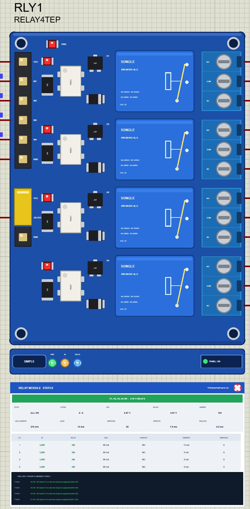
The board looks like the one on your desk: the black input header on the left, the yellow JD-VCC jumper under it, the red PWR LED at the top, and per channel the red IN LED, the white PC817, the transistor, the diode, the blue SONGLE relay and the blue screw terminal. While the simulation runs, the IN LED of a channel lights while its input is LOW, and the arm of the symbol printed on each relay moves from NC to NO and turns yellow while the relay is ON. Under the board is the TEP strip with the PWR, IN and RELAY LEDs and the panel button. The strip, its LEDs, the moving arm and the panels are TEP additions; the real board has none of them.
The Simple device adds the STATUS panel. Its banner says what the module does, here "K1, K2, K3, K4 ON - 4 OF 4 RELAYS". Ten readouts follow: the state, the active relays, VCC, JD-VCC, the jumper, the coil current (275 mA for four relays), the load current on the contacts, the number of switchings, and the operate and release times of the last switching, 7.0 ms and 5.0 ms. Under them is a row per relay with its input, its state, its coil current, the closed contact and the current through it, and at the bottom the last four events. The banner turns red with the latest warning. The red X closes the panel, and the PANEL button on the strip opens it again.
The Advance device keeps the schematic clean: only the board and its strip. Its live data opens in a pop-up window at Run, and the OPEN PANEL button brings the window back if you close it. On both styles you can click the yellow JD-VCC jumper during the simulation to pull it and click again to put it back. The property JUMPER sets it at the start.
The Demo Circuit
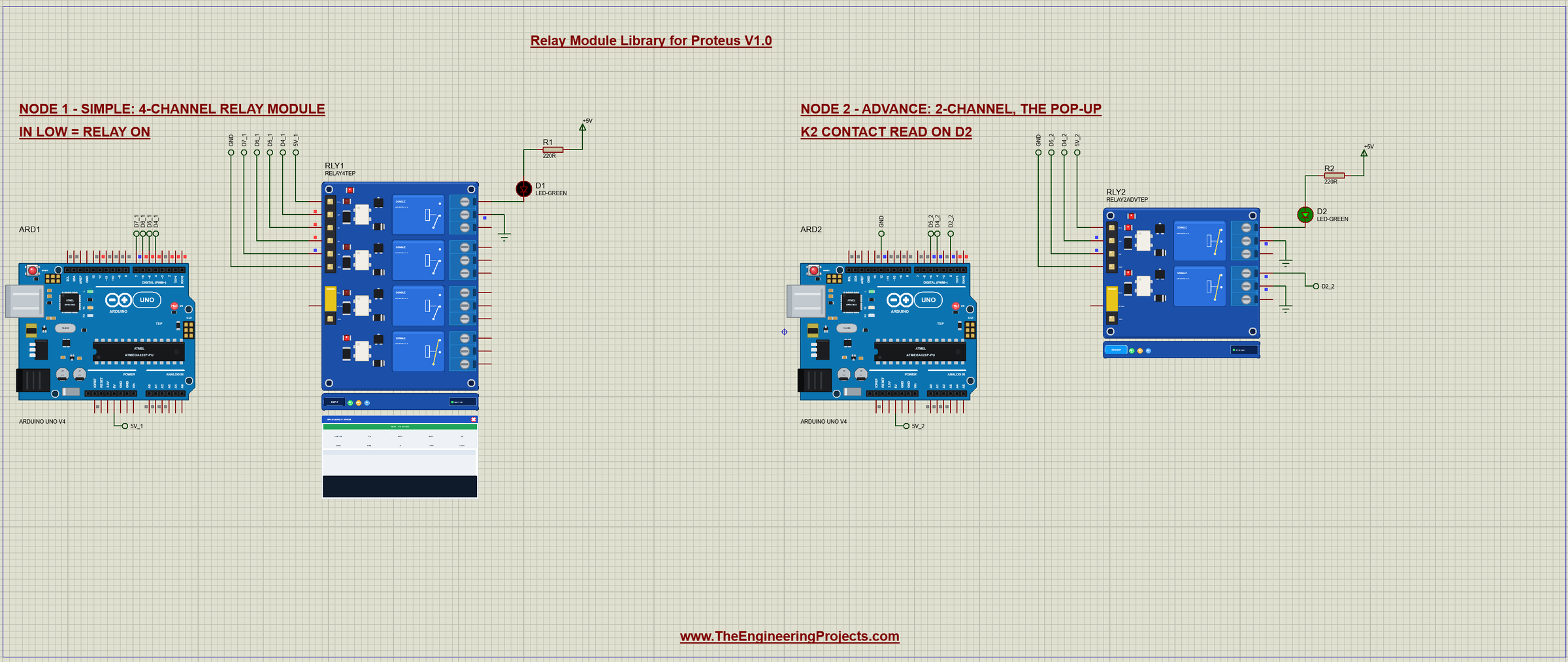
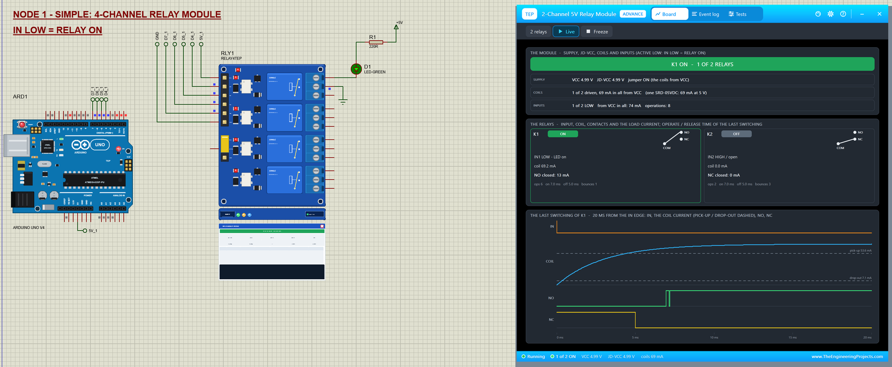
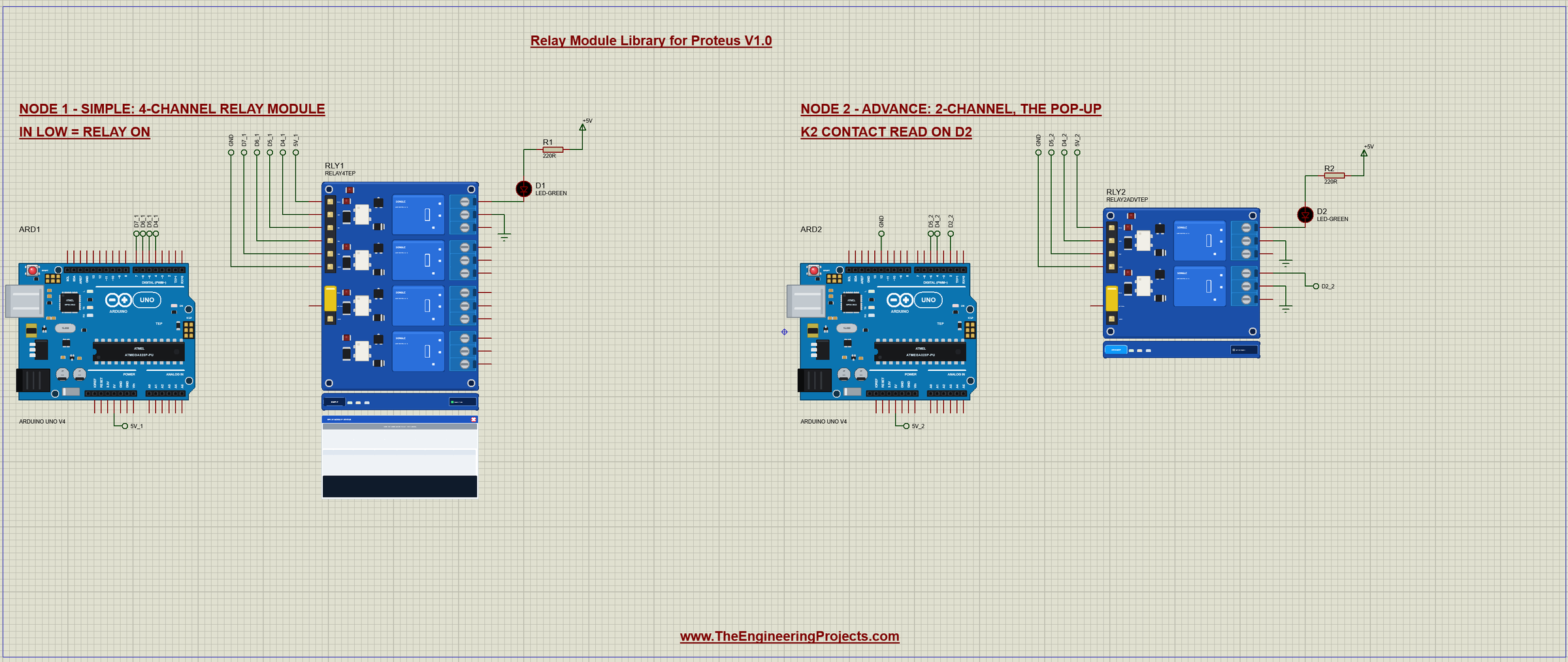
The demo project has two nodes. Each one is an Arduino UNO V4.0 from our Arduino UNO Library for Proteus V4.0 with a relay module. Both UNOs run the same Relay_Demo.hex. Node 1 drives the 4-channel Simple module, node 2 the 2-channel Advance module with its pop-up. On both, relay K1 switches a green LED with a 220 ohm resistor from +5V, so you can see the contact work. Node 2 also reads the contact of K2 back into the Arduino, to show the bounce.
Wiring
| Relay module | Arduino UNO | Note |
|---|---|---|
| VCC | 5V | the inputs and, with the jumper on, the coils |
| GND | GND | common ground |
| IN1 - IN4 | D4 - D7 | any digital pins; LOW = the relay ON |
| JD-VCC | open (jumper on) | or a separate 5 V supply with the jumper off |
| COM, NO, NC | the load | NO is closed while the relay is ON, NC while it is OFF |
In Proteus every board pin reaches its UNO through a wire with a net label: D4_1 to D7_1 and 5V_1 for node 1, and D4_2, D5_2, 5V_2 and D2_2 for node 2. The LED of each node sits on the low side: +5V, the 220 ohm resistor, the LED, then NO1, and COM1 goes to GND. The serial monitor needs no wires at all, because it is built into the UNO V4.0.
Node 1: the 4-Channel Simple Module
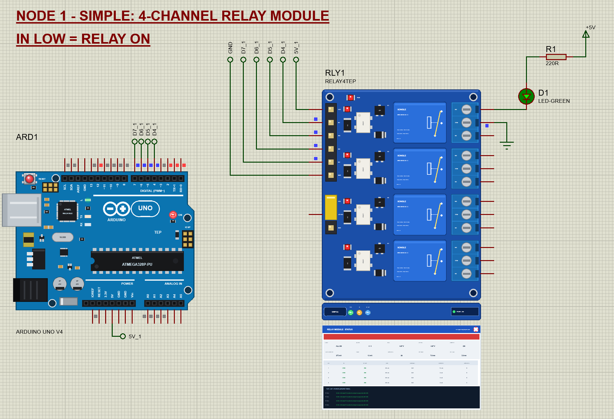
Node 1 shows the whole story on the schematic. The tour switches the relays on one after the other, 600 ms each, then all four for 1.5 s, then all off for 1 s, and starts again. Watch the IN LEDs, the moving arms and the green LED, which lights whenever K1 is ON.
Node 2: the 2-Channel Advance Module
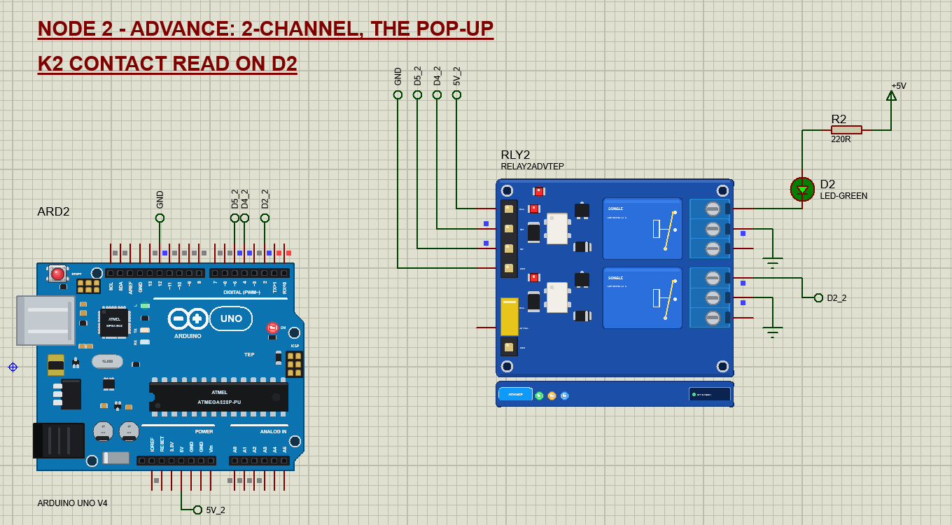
Node 2 runs the same sketch on the 2-channel Advance module. Its D12 is connected to GND, which tells the sketch to drive only two relays. K1 switches the LED D2 with R2, and K2's contact is wired back into the Arduino: COM2 to GND and NO2 to the UNO's D2, an input with its internal pull-up. When K2 closes, D2 goes LOW, and the sketch counts every change of D2.
The Arduino Code
The demo sketch uses only the Arduino core, no library. New to Arduino? Start with Arduino Tutorial for Beginners and Introduction to Arduino UNO. The sketch begins with its pins:
const uint8_t RELAY_PIN[4] = {4, 5, 6, 7};      // IN1 - IN4
const uint8_t CONTACT_PIN = 2;                  // relay 2's NO contact (node 2), COM2 to GND
const uint8_t SELECT_PIN = 12;                  // open = a 4-channel module, to GND = a 2-channel module
One small function hides the active LOW logic from the rest of the sketch:
void relay(uint8_t k, bool on) {                // on = true: the relay ON = IN LOW (active LOW)
  relayOn[k] = on;
  digitalWrite(RELAY_PIN[k], on ? LOW : HIGH);
}
The most important lines are in setup(). After a reset every Arduino pin is an input, and its output latch is LOW. If the sketch calls pinMode(OUTPUT) first, the pin drives LOW at once, and every relay clicks ON until the sketch writes HIGH. So the sketch writes HIGH before it makes the pin an output:
  for (uint8_t k = 0; k < RELAYS; ++k) {
    digitalWrite(RELAY_PIN[k], HIGH);           // HIGH first: the relay stays OFF ...
    pinMode(RELAY_PIN[k], OUTPUT);              // ... when the pin becomes an output
    relayOn[k] = false;
  }
The tour switches the relays one after the other:
  if (stage == 0) {                             // one after the other, 600 ms each
    if (step > 0) relay(step - 1, false);
    if (step < RELAYS) { relay(step, true); printRelay(step); ++step; nextAt = now + 600; return; }
To read K2's contact back, D2 has an interrupt on every change. The interrupt only counts the edges and keeps the time of the first and the last one:
void onContact() {
  const unsigned long t = micros();
  if (!edges) firstUs = t;
  lastUs = t;
  ++edges;
}
When D2 has been quiet for 20 ms, reportContact() prints how many edges came and how long they took. One edge is a clean change; more than one is bounce:
  Serial.print(F("   D2 (NO2): ")); Serial.print(n); Serial.print(n == 1 ? F(" edge") : F(" edges"));
  if (n > 1) { Serial.print(F(" in ")); Serial.print((b - a) / 1000.0, 2); Serial.print(F(" ms")); }
  Serial.println(n > 1 ? F(" - the contact bounced: debounce it") : F(" - a clean change"));
The commands make the classic mistakes on purpose. PULSE holds an input LOW for a few milliseconds:
relay(k, true); delay(v2); relay(k, false);PWM puts analogWrite() on IN2 or IN3. Because the input is active LOW, the sketch inverts the duty, so PWM 2 128 keeps IN2 LOW for half of each period:
analogWrite(RELAY_PIN[k], 255 - constrain(v2, 0, 255)); // active LOW: the duty of the LOW partGLITCH repeats the start-up mistake: it makes the pin an input with its latch LOW, as after a reset, then calls pinMode(OUTPUT) first and writes HIGH 30 ms later:
    pinMode(RELAY_PIN[k], INPUT); digitalWrite(RELAY_PIN[k], LOW);   // as after a reset: an input, its output latch LOW
    delay(5);
    pinMode(RELAY_PIN[k], OUTPUT);              // the pin drives its LOW latch: the relay switches ON ...
    delay(30);                                  // ... while the sketch does its other setup ...
    digitalWrite(RELAY_PIN[k], HIGH);           // ... until it writes HIGH 30 ms later
The HEX file is in the package. To change the sketch, open it in the Arduino IDE and export the compiled binary, as in How to get the HEX file from Arduino. It needs 8,428 bytes of flash and 332 bytes of RAM.
The Serial Monitor
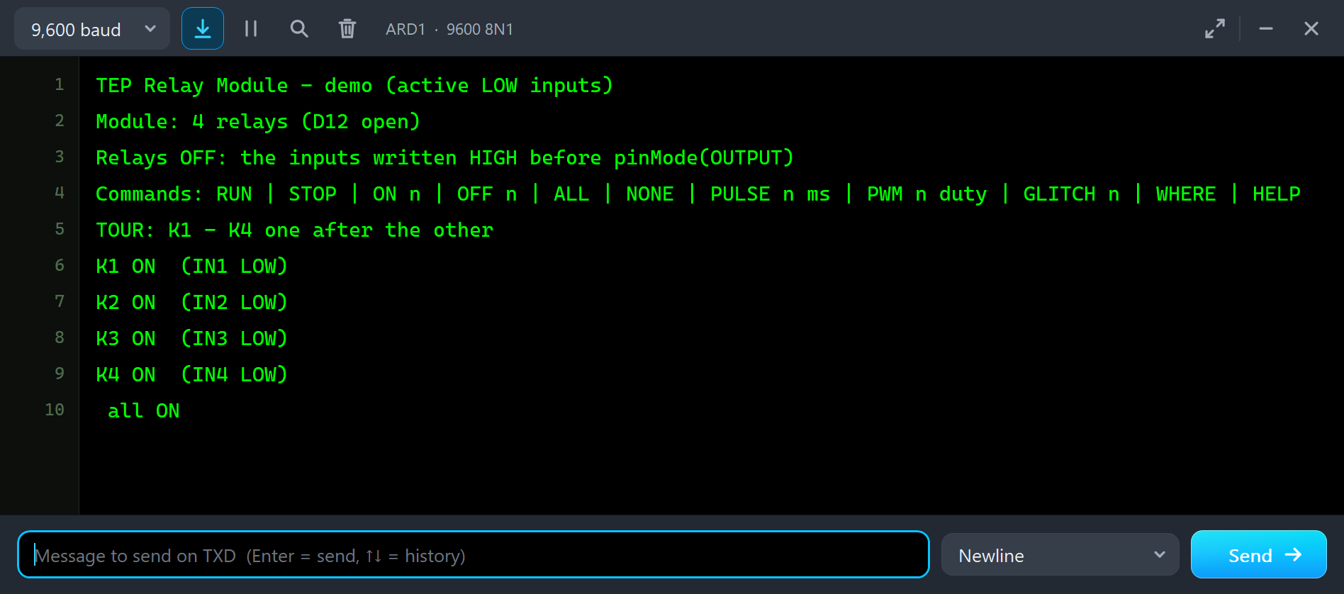
Both UNOs have the serial monitor built in, and it opens at Run. The screenshots use its Simple interface. Node 1 starts with "TEP Relay Module - demo (active LOW inputs)" and "Module: 4 relays (D12 open)", then the tour lists every relay it switches. Node 2 prints the same with two relays, plus the contact of K2:
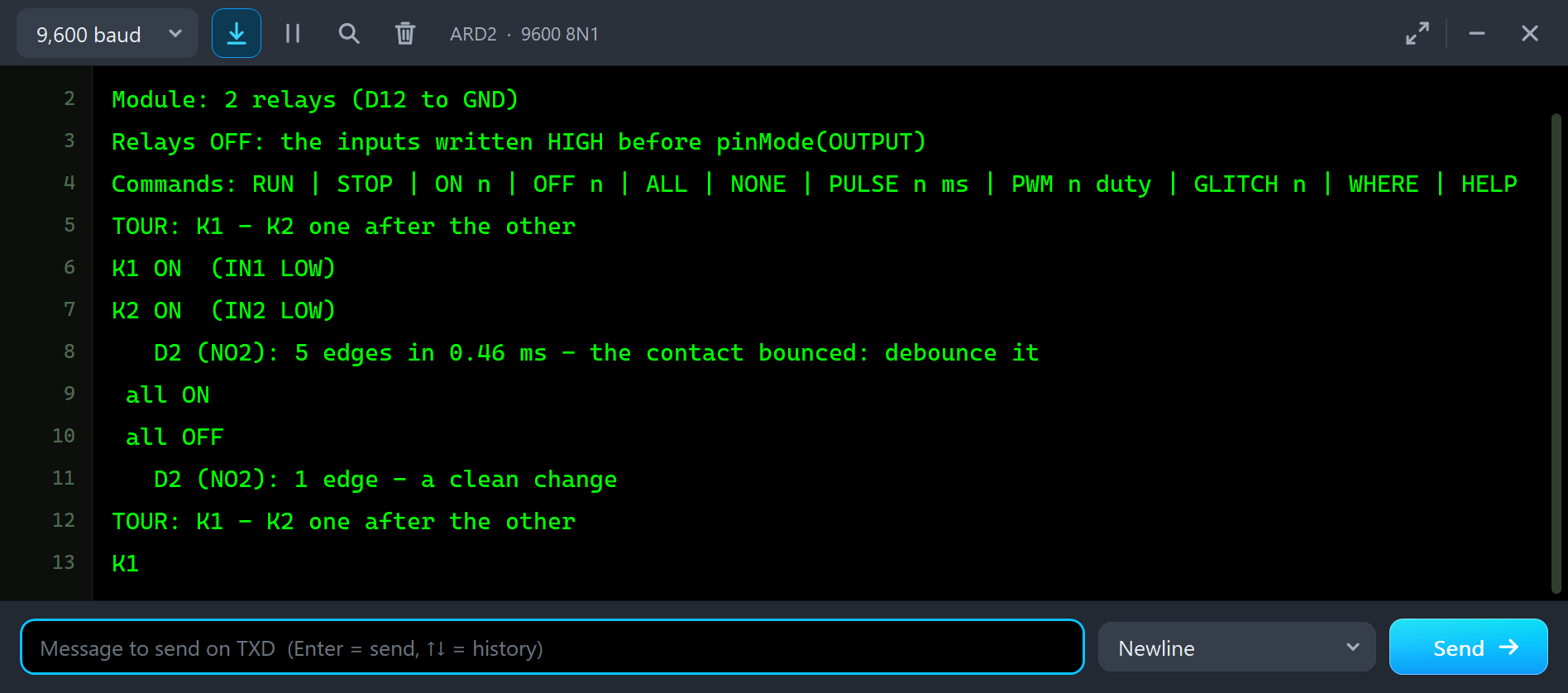
Module: 2 relays (D12 to GND)
Relays OFF: the inputs written HIGH before pinMode(OUTPUT)
Commands: RUN | STOP | ON n | OFF n | ALL | NONE | PULSE n ms | PWM n duty | GLITCH n | WHERE | HELP
TOUR: K1 - K2 one after the other
K1 ON  (IN1 LOW)
K2 ON  (IN2 LOW)
   D2 (NO2): 5 edges in 0.46 ms - the contact bounced: debounce it
 all ON
 all OFF
   D2 (NO2): 1 edge - a clean change
Every time K2 closes, the Arduino sees its contact bounce: here 5 edges in 0.46 ms. When K2 opens, NO simply breaks, and D2 sees one clean edge. This is the real behaviour of a relay contact, and the reason why a sketch that counts contact closings must debounce them: wait 5 to 20 ms after the first edge before it reads the input again.
Commands
Type a command in the monitor and press Enter. STOP stops the tour and the relays stay as they are, ON 1 and OFF 1 switch one relay, ALL and NONE switch them all, PULSE 1 20 holds IN1 LOW for 20 ms, PWM 2 128 puts PWM on IN2, GLITCH 1 repeats the start-up mistake on IN1, WHERE prints the state of each relay, RUN starts the tour again and HELP lists them all.
The Advance Pop-Up Window
At Run, the Advance device opens TEP Relay Module Advance, with the look of our TEP Serial Monitor Advance for Proteus. It has three tabs, Board, Event log and Tests, plus Settings and Help behind the gear and question mark icons.
The Board Page
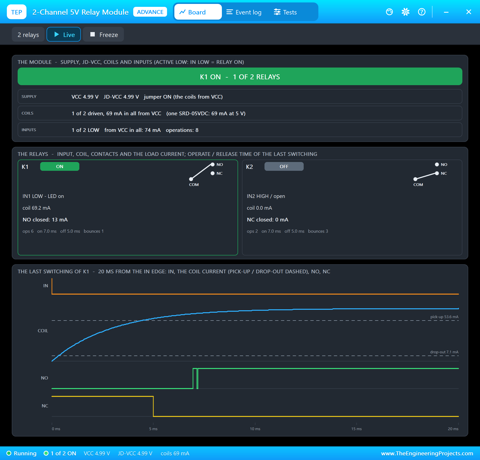
The top card is the module: the state in the banner, the supply with VCC, JD-VCC and the jumper, the coils with their current, and the inputs. Under it is a card per relay with its state, its contact symbol, the input, the coil current, the closed contact and its current, the number of operations, and the operate and release times and the bounces of its last switching. K1's NO contact carries the 13 mA of the LED.
The bottom card is the best part: the last switching, 20 ms from the input edge. You see IN go LOW, the coil current rise along its curve and cross the dashed pick-up line at 53.6 mA, NC break at 5 ms, and NO make at 7 ms with its bounce. That is break before make, measured on the model's own signals. Freeze holds the page for a closer look.
The Test Tools
The Tests tab holds three tools. Each one reads the module as the model sees it, and where it judges, gives every row a green, amber or red verdict.
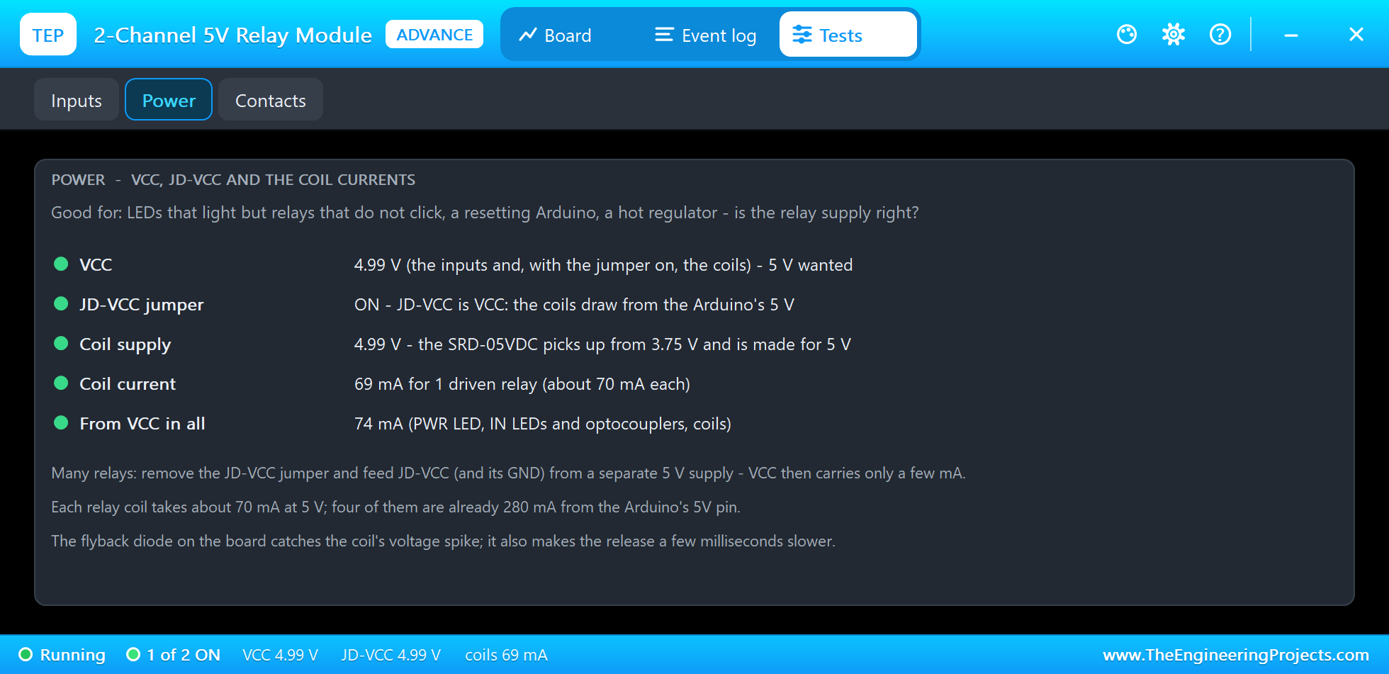
Power is good for LEDs that light but relays that do not click, a resetting Arduino or a hot regulator. It checks VCC, the jumper, the coil supply against the 3.75 V pick-up level, the coil current, which turns red above a USB port's budget when it comes from VCC, and the current from VCC in all. Here one relay is ON: 69 mA for its coil and 74 mA from VCC with the LEDs and the optocoupler.
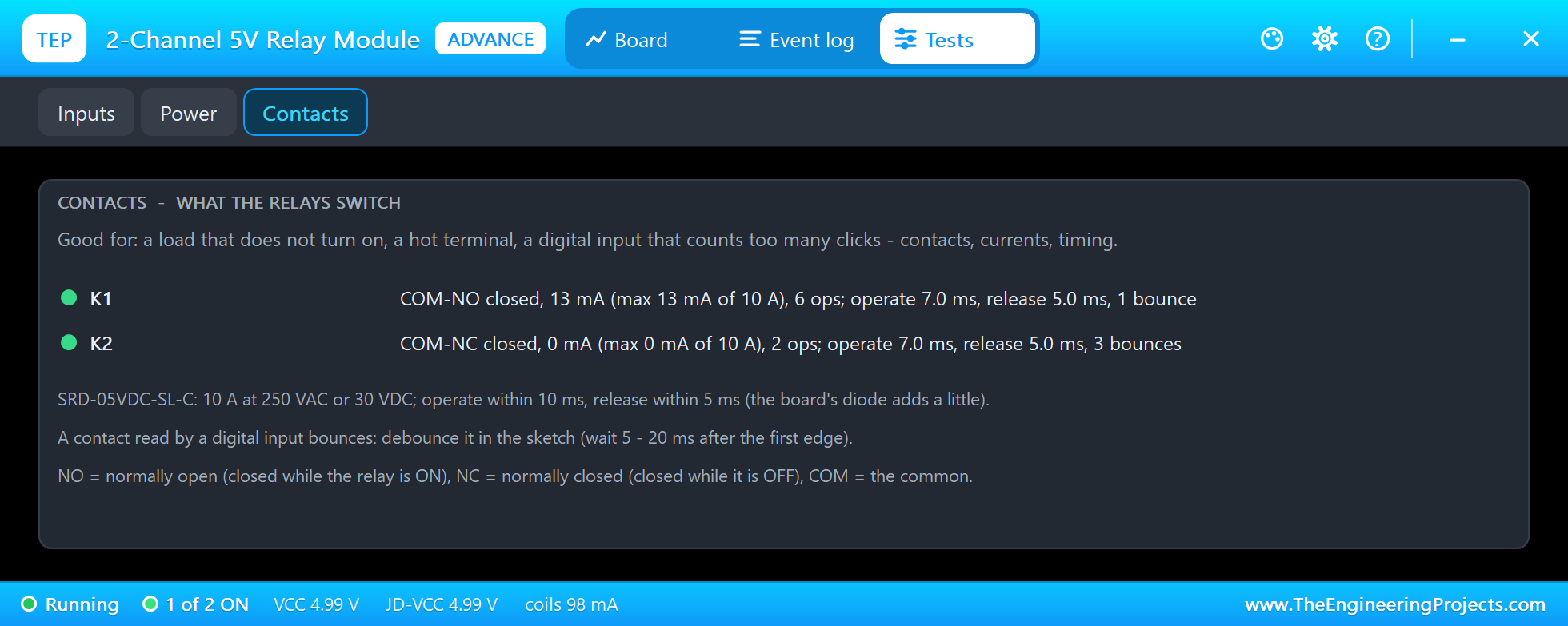
Contacts is good for a load that does not turn on, a hot terminal, or an input that counts too many clicks. For each relay it shows the closed contact and its current, the highest current so far against the 10 A rating, the operations, the operate and release times and the bounces of the last switching. The third tool, Inputs, we will meet with the PWM mistake below.
Classic Relay Module Mistakes, Simulated
The demo sketch can make the most common relay module mistakes on purpose, so you can see what they look like before they happen on your desk. All of them were run in the final test.
Pulses Too Short and the Start-Up Click
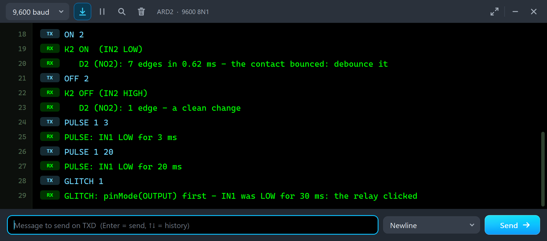
ON 2
K2 ON  (IN2 LOW)
   D2 (NO2): 7 edges in 0.62 ms - the contact bounced: debounce it
OFF 2
K2 OFF (IN2 HIGH)
   D2 (NO2): 1 edge - a clean change
PULSE 1 3
PULSE: IN1 LOW for 3 ms
PULSE 1 20
PULSE: IN1 LOW for 20 ms
GLITCH 1
GLITCH: pinMode(OUTPUT) first - IN1 was LOW for 30 ms: the relay clicked
A relay is slow. PULSE 1 3 holds IN1 LOW for 3 ms, but the coil current needs more time to reach the pick-up level (about 4.5 ms): K1 does not move. PULSE 1 20 is long enough: K1 switches ON 7 ms after the edge and OFF 5 ms after the input goes HIGH again, so it is ON for 18 ms. GLITCH 1 makes the start-up mistake: the pin becomes an output while its latch is LOW, and IN1 stays LOW for 30 ms until the sketch writes HIGH. The relay clicks ON for 28 ms. On a real project that is the pump, the lock or the heater that switches on for a moment every time the Arduino resets.
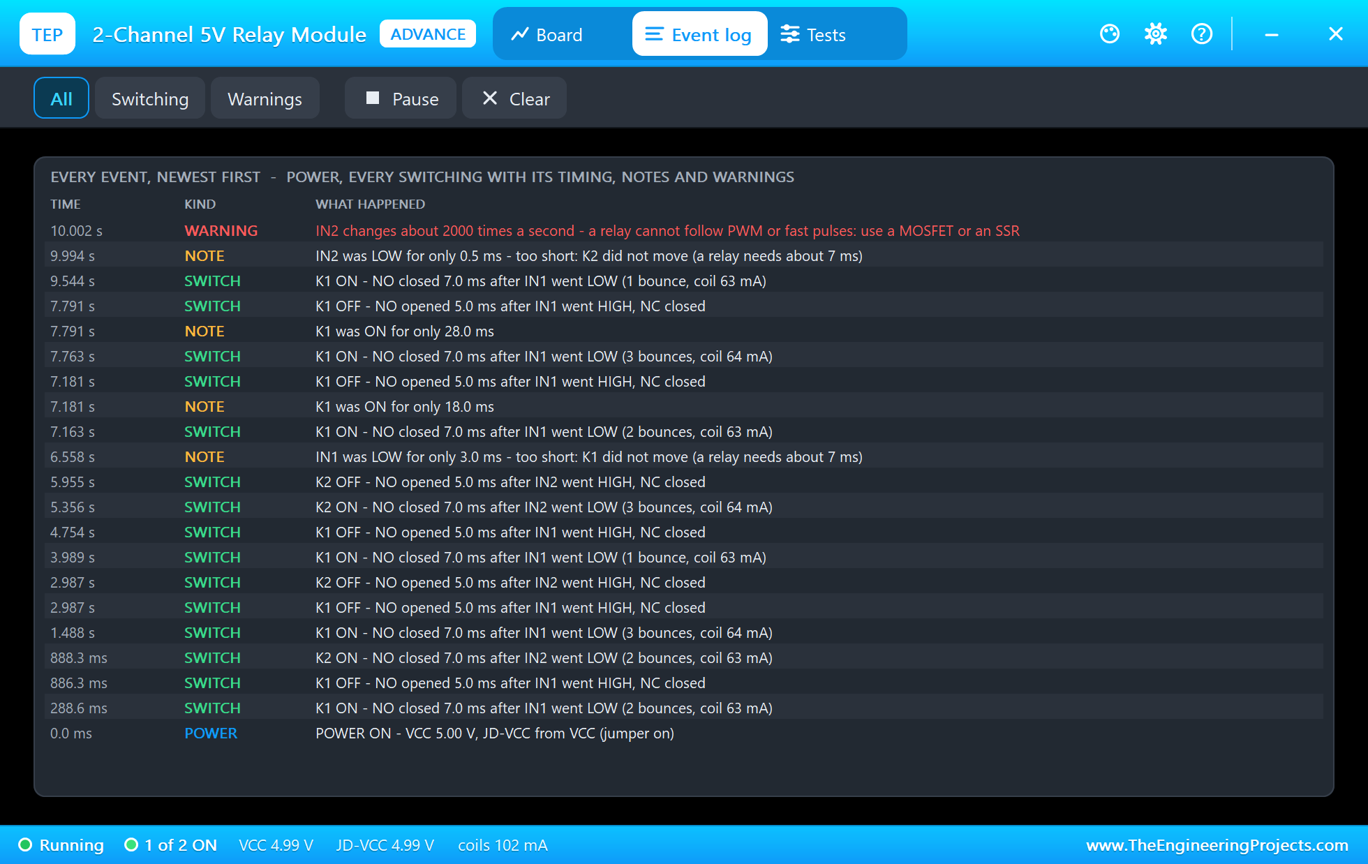
The Event log lists every switching with its timing, for example "K1 ON - NO closed 7.0 ms after IN1 went LOW (3 bounces, coil 64 mA)". The coil current is still rising at that moment; it settles at 69 mA. For the mistakes it adds notes: "IN1 was LOW for only 3.0 ms - too short: K1 did not move (a relay needs about 7 ms)", then "K1 was ON for only 18.0 ms" and "K1 was ON for only 28.0 ms". Filter the log by switching or warnings, pause it, or clear it.
PWM on a Relay Input
A relay is not a MOSFET. What happens if a sketch tries to dim a lamp through a relay with analogWrite()? Type PWM 2 128:
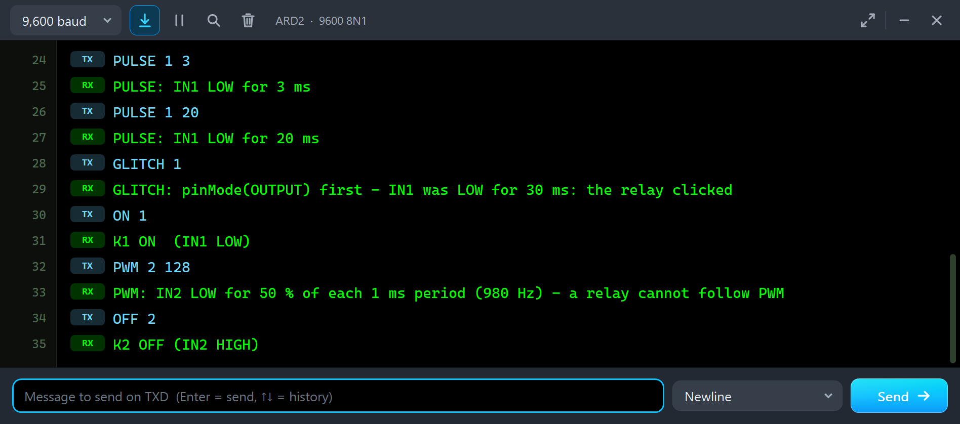
ON 1
K1 ON  (IN1 LOW)
PWM 2 128
PWM: IN2 LOW for 50 % of each 1 ms period (980 Hz) - a relay cannot follow PWM
OFF 2
K2 OFF (IN2 HIGH)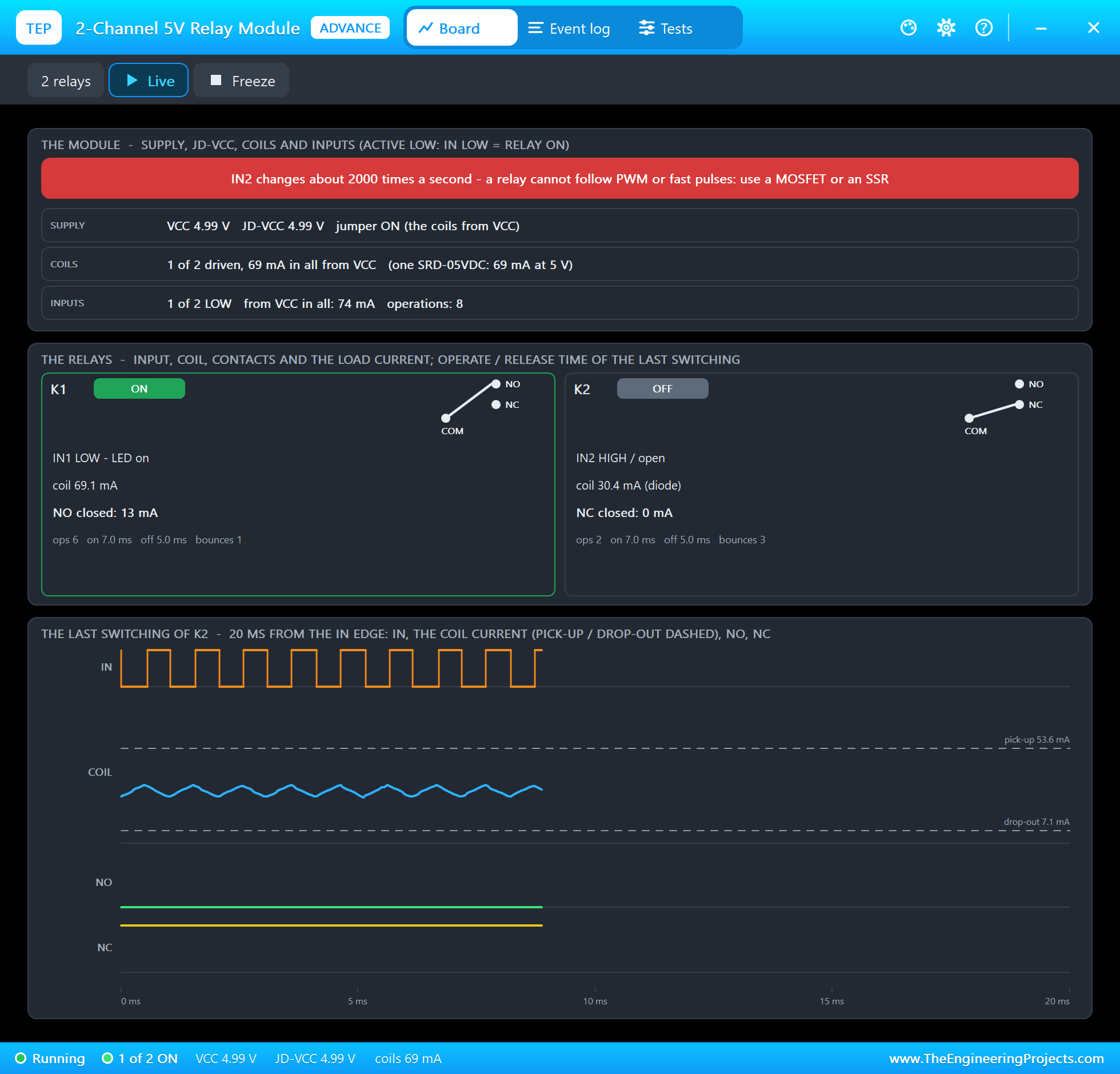
IN2 now switches every half millisecond. The coil current cannot follow: it rises a little while IN2 is LOW and falls through the diode while it is HIGH, and settles at about 30 mA, far below the 53.6 mA pick-up level. K2 stays OFF. The banner shows the warning "IN2 changes about 2000 times a second - a relay cannot follow PWM or fast pulses: use a MOSFET or an SSR".
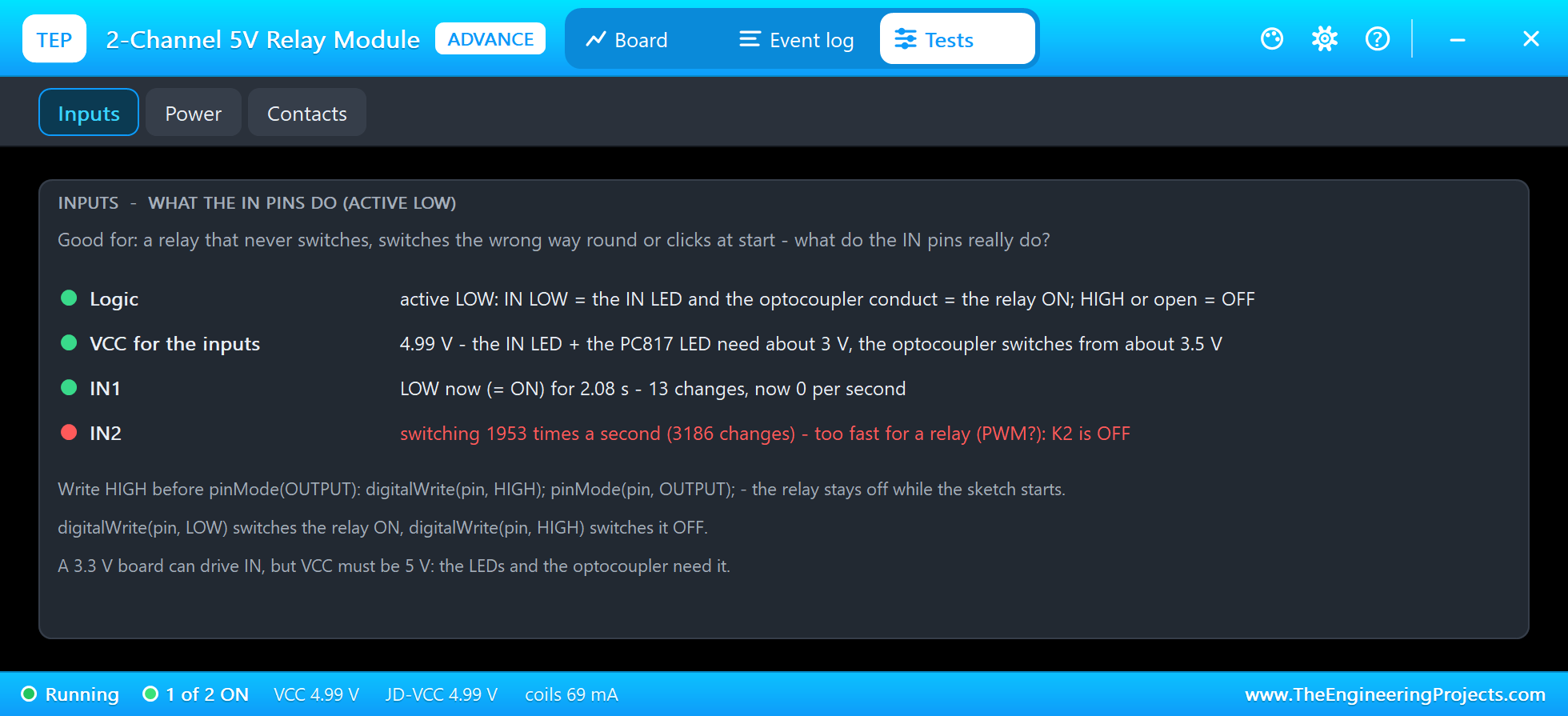
Inputs is the tool for a relay that never switches, switches the wrong way round or clicks at start. It shows the active LOW logic, VCC for the inputs, and for each input its level, how long it has been there, its changes and their rate. IN2 is red: "switching 1953 times a second (3186 changes) - too fast for a relay (PWM?): K2 is OFF". 1953 changes a second are the two edges of each period of the UNO's 976 Hz PWM on D5. An interesting detail: a relay that is already ON holds on a 50 percent PWM, because its current stays above the drop-out level. So PWM does not even work as an off switch.
Pulling the JD-VCC Jumper
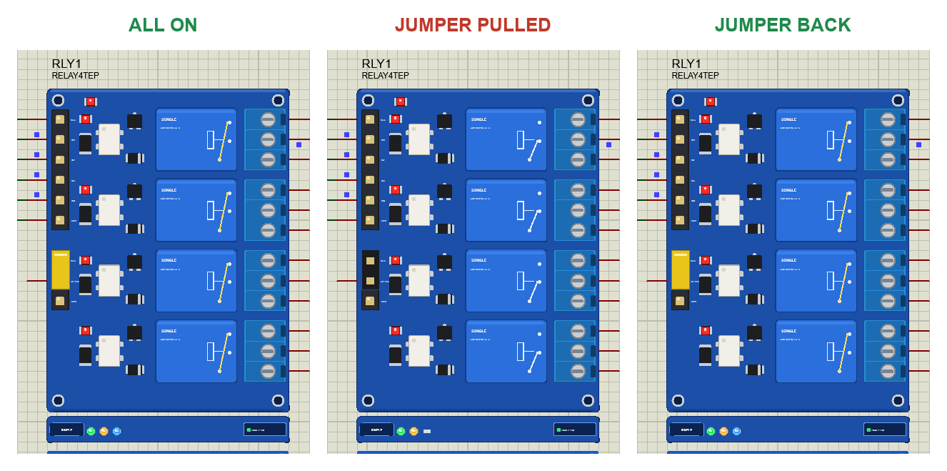
The JD-VCC jumper is the part of these modules that confuses people most. To see what it does, type ALL on node 1, then click the yellow jumper on RLY1. We did it with the mouse in the final run. The coils lose their supply, and all four relays drop out, although their inputs are still LOW and the IN LEDs still light. The red IN LEDs only show the input; they say nothing about the relay. Click the jumper again, and the relays switch on 7.0 ms later.
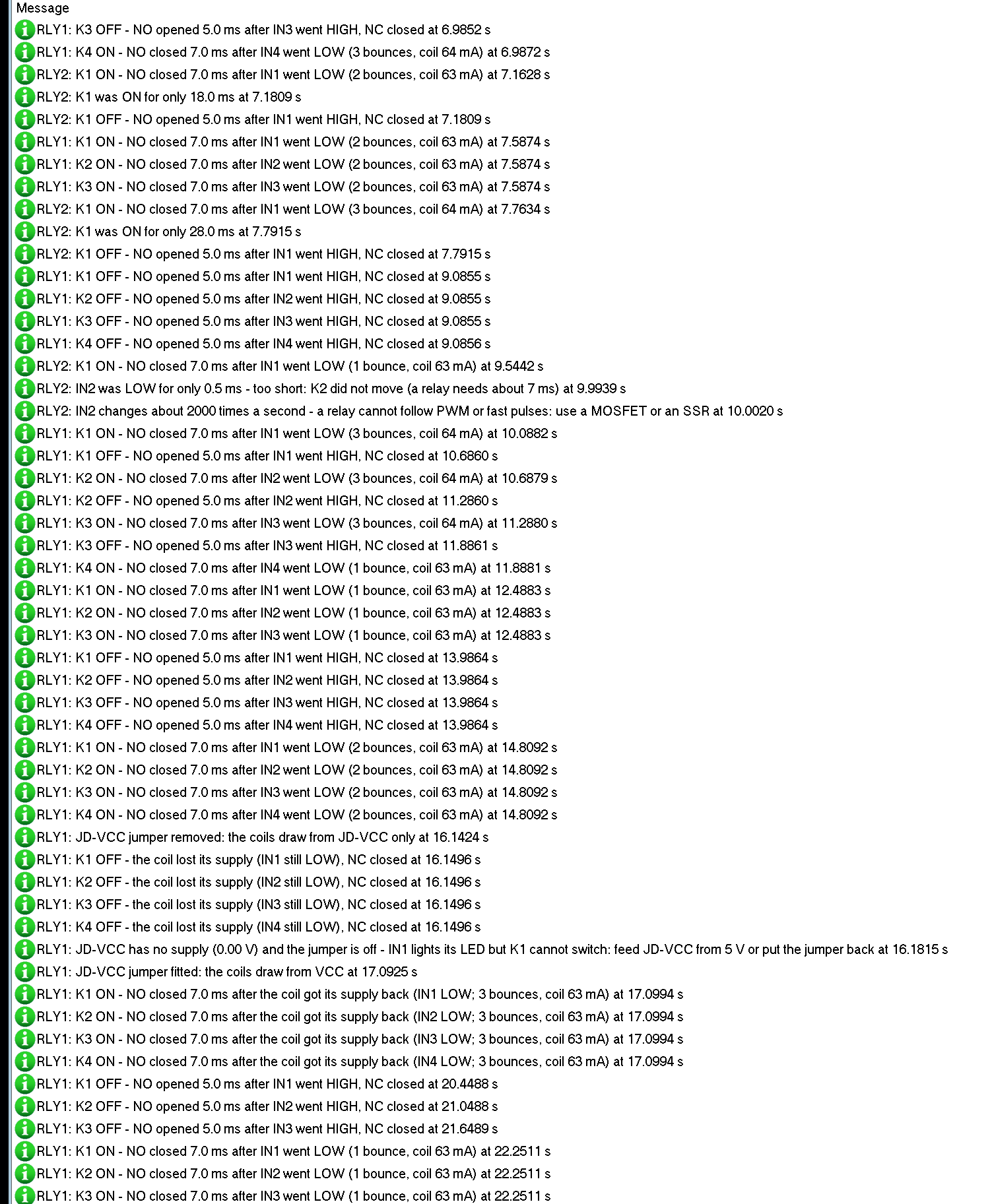
RLY1: JD-VCC jumper removed: the coils draw from JD-VCC only at 16.1424 s
RLY1: K1 OFF - the coil lost its supply (IN1 still LOW), NC closed at 16.1496 s
RLY1: JD-VCC has no supply (0.00 V) and the jumper is off - IN1 lights its LED but K1 cannot switch:
      feed JD-VCC from 5 V or put the jumper back at 16.1815 s
RLY1: JD-VCC jumper fitted: the coils draw from VCC at 17.0925 s
RLY1: K1 ON - NO closed 7.0 ms after the coil got its supply back (IN1 LOW; 3 bounces, coil 63 mA) at 17.0994 s
The log tells the whole story, and the warning says what to do: feed JD-VCC from 5 V or put the jumper back. On a real board this is exactly what happens when the jumper is removed for isolation and the separate supply is forgotten: the LEDs light, and nothing clicks.
How the Model Works
Proteus solves the analog part of a circuit in time steps and runs the digital part, here the Arduino's writes to the IN pins, between them. The model keeps every input edge with its exact time. Over each analog step it integrates the coil current in 10 us pieces from those edges and the supply on VCC and JD-VCC, so a 3 ms pulse in the middle of a step still gets its full 3 ms. When the current crosses the pick-up or drop-out level, the armature starts its travel, and the model knows in advance when NC breaks, when NO makes and when each bounce comes.
The contacts are conductances in the circuit: 20 siemens, which is 50 mohm, when closed, and practically open otherwise. The model shortens the analog steps so that every contact change lands exactly on a step: 100 us while a relay moves, 1 ms when all are still. That is how an Arduino input on a contact, like D2 in the demo, sees every bounce. The supply currents go back into the circuit too: the LEDs and optocouplers on VCC, and the coils on VCC or JD-VCC.
Troubleshooting
- The relay is ON when the sketch says OFF: these modules are active LOW. LOW means ON.
- A relay clicks once when the sketch starts: write HIGH before
pinMode(OUTPUT). - The IN LED lights but the relay does not click: the jumper is off and JD-VCC has no supply, or VCC or JD-VCC is below about 3.75 V. The Power tool shows it.
- Nothing lights: no VCC (the PWR LED is dark), or the input is HIGH or open.
- A relay does nothing with analogWrite(): a relay cannot follow PWM. Use a MOSFET or a solid state relay.
- The load does not switch: check COM, NO and NC. NO closes while the relay is ON, NC while it is OFF.
- An input that reads a contact counts several clicks: the contact bounces. Debounce it in the sketch.
- No part, no relays or no monitor: TEPRELAY.DLL or TEPARDUINO.DLL is missing from MODELS and the project folder; a closed monitor opens again with a click on the UNO's USB port.
Things to Know Before Using a Real Relay Module
- Mind the coil current: each relay takes about 70 mA. Four relays are 280 mA and eight are 560 mA, more than a USB port gives. Remove the jumper and feed JD-VCC and its GND from a separate 5 V supply.
- Full isolation: with the jumper off and JD-VCC from its own supply, the relay side does not even need the Arduino's GND. Connect only VCC and the IN pins.
- 5 V on VCC: a 3.3 V board can drive the IN pins, but VCC must be 5 V for the LEDs and the optocouplers.
- Mains is dangerous: keep the high-voltage side away from the low-voltage side, use a fuse and an enclosure. If you are not sure, switch a low-voltage load.
- Relays are slow and wear out: about 7 ms to switch and about 100,000 operations at full load. For PWM or fast switching use a MOSFET or a solid state relay.
Limitations of the Simulation
- Not modelled: contact arcing and wear, the AC ratings of the contacts in detail (the model checks the current only), the heating of the coil, the current transfer of the optocoupler in detail (a threshold), and damage from a wrong supply (the model only warns).
- Some 1-channel boards have an H / L trigger jumper; this model is the common active LOW board.
- The strips, their LEDs, the moving arms and the panels are TEP additions.
- The model is our own, written from the SONGLE SRD-05VDC-SL-C data and the typical circuit of these modules. This library is not made or endorsed by SONGLE, the makers of these modules or Labcenter.
- Licences: the demo's HEX file contains the Arduino AVR core 1.8.6 with LGPL-licensed code; its source link is in the README.
- Tested in Proteus 8.5 in October 2026 (the demo as shipped on two Arduino UNO V4.0 boards with their built-in monitors: the tour on both nodes, the contact bounce on D2, the short pulses, the start-up click, PWM, the JD-VCC jumper with the mouse, the pop-up and the three tools; about 0.3 x real time with the pop-up and both monitors open). Proteus 7 is not supported.
So, that was all about the Relay Module Library for Proteus V1.0. I hope the active LOW inputs, the JD-VCC jumper, the 7 ms of a relay and its bouncing contacts are clear now, so your relays click exactly when you want from the first run. If you use the Relay Module Library for Proteus in a project, please share it in the comments or in our forum, and if you have any questions, ask in the comments and I will help you out. Till the next tutorial, take care and have fun!
Comments
0