


LDR Sensor Library for Proteus (Light Sensor Module + Arduino)


Hello friends, I hope you all are doing great. Today, I am going to share our new LDR Sensor Library for Proteus. An LDR (light dependent resistor, also called a photoresistor) is the simplest light sensor there is: its resistance drops when more light falls on it. Most makers know it from the small blue LDR light sensor module with an LM393 comparator, a blue pot and two outputs, A0 and D0. With this LDR Sensor Library for Proteus, you set the light on the sensor, from a moonlit night to direct sunlight, and your Arduino reads A0 with analogRead() and D0 with digitalRead(), exactly as on a real board.
This is the first LDR library from our team, version 1.0. You get two devices: LDR Simple, with a live light scene panel on the schematic, and LDR Advance, with a pop-up window and four measured sensor test tools. The LDR is simulated as a real analog part, with its slow response in the dark, and the LDR Arduino Proteus demo runs an automatic night lamp on two Arduino UNOs, shown in the compact Simple interface of our TEP Serial Monitor.
NOTICE: This library is very special to our team. Our LDR model is a real analog part in Proteus's SPICE simulator: the GL5528's light curve, the board's 10 k divider on A0, the LM393 comparator with its open-collector D0, the pot, and the LDR's slow recovery in the dark. It took our team a lot of hard work, many test runs and many design changes. Your feedback is the fuel that keeps us going, so please tell us what you think in the comments below or in the LDR Sensor Library board of our forum. And if our free libraries help you, you can buy us a coffee. So, let's get started with the LDR Sensor Library for Proteus:
What is an LDR Light Sensor Module?
An LDR (light dependent resistor) is a small resistor made of cadmium sulphide (CdS), with an orange zig-zag track on a round face. In the dark it has about 1 megaohm (1,000,000 ohms), in bright light only a few hundred ohms. The common 5 mm part is the GL5528: about 15 k (15,000 ohms) at 10 lux, falling about 0.7 decades for every decade of light.
Light is measured in lux. A moonlit night gives about 0.2 lux, a dim room about 10 lux, a lit living room about 300 lux, a cloudy day about 1000 lux, and direct sunlight up to about 100000 lux. That is a range of more than a million to one, which is why our panels use a log scale.
The LDR light sensor module puts the LDR on a small blue board with everything an Arduino needs:
- A0, the analog output: a 10 k resistor from VCC to A0 and the LDR from A0 to GND form a voltage divider. More light means less resistance and a lower A0; darkness means a higher A0.
- D0, the digital output: an LM393 comparator compares A0 with a reference voltage set by the blue pot (a trimmer). D0 is LOW in light and HIGH in the dark.
- Two LEDs: a red PWR LED, and a green D0 LED that lights while D0 is LOW, so in light.
- Four pins: VCC, GND, D0 and A0.
Beginners often expect A0 to rise with the light. On this module it is the other way round: the darker it gets, the higher the reading. LDR modules switch night lamps and street lights and answer the question "day or night?".
The LDR Module at a Glance
| Feature | Value |
|---|---|
| Sensor | GL5528 photoresistor (CdS LDR), 5 mm |
| LDR resistance | About 1 Mohm in the dark, about 15 k at 10 lux, a few hundred ohms in bright light |
| A0 | Analog, 0 to VCC; higher = darker (10 k pull-up and the LDR as a divider) |
| D0 | Digital, the LM393's open-collector output with a 10 k pull-up; LOW = light, HIGH = dark |
| Threshold | The blue pot sets the light level of D0; the middle position is about 18 lux |
| Hysteresis | None on this board |
| LEDs | PWR (red), D0 (green, lit in light) |
| Pins | VCC, GND, D0, A0 |
| Supply | 3.3 to 5 V; A0 and the pot's reference follow VCC |
LDR Terms You Will See in This Article
| Term | Meaning |
|---|---|
| LDR | Light dependent resistor (photoresistor): less resistance in more light |
| Lux | The unit of the light falling on a surface |
| GL5528 | The common 5 mm LDR on these modules |
| A0 | The analog output, the divider voltage; HIGHER means DARKER |
| D0 | The digital output of the LM393: LOW = light, HIGH = dark |
| LM393 | A comparator: it switches D0 when A0 crosses the pot's reference |
| Pot | The blue trimmer that sets the reference, so the light level where D0 switches |
| ADC | The UNO's 10-bit analog-to-digital converter: 0 to 1023 for 0 to 5 V |
| Hysteresis | A gap between the switch-on and the switch-off level; this board has none |
| Dark tail | The LDR's slow recovery in the dark: the reading creeps up for seconds |
How the LDR Module Works
The Divider: Why A0 Rises in the Dark
A0 = VCC x R / (R + 10 k), where R is the LDR's resistance. Our model uses the GL5528 curve: G = 1 / 1 Mohm + (lux / 10)^0.7 / 15 k, and R = 1 / G + 100 ohm for the contacts. At 300 lux, R is about 1.49 k, so A0 = 5 V x 1.49 / 11.49 = 0.647 V, and the UNO reads 1024 x 0.647 / 5 = 132. At night (0.2 lux), R is about 188 k, A0 is 4.75 V and the ADC reads 972.
| Preset | Light | LDR | A0 | ADC |
|---|---|---|---|---|
| NIGHT | 0.2 lux | 188 k | 4.75 V | 972 |
| DIM ROOM | 10 lux | 14.9 k | 2.99 V | 612 |
| INDOOR | 300 lux | 1.49 k | 0.647 V | 132 |
| CLOUDY DAY | 1000 lux | 697 ohm | 0.326 V | 67 |
| TORCH ON SENSOR | 20000 lux | 173 ohm | 0.085 V | 17 |
| SUNNY DAY | 50000 lux | 139 ohm | 0.068 V | 14 |
Notice how the ADC squeezes the bright end: from 1000 to 50000 lux, the reading moves only from 67 to 14 counts. An LDR module tells dark from light very well, but it is not a precise light meter.
D0: the LM393 Comparator and the Pot
The LM393 compares A0 with the pot's reference. While A0 is below the reference (bright), its open-collector output pulls D0 LOW and the green D0 LED lights. Above it (dark), the 10 k pull-up makes D0 HIGH. The middle pot position gives 2.50 V, which A0 reaches at about 18 lux, a dim room. A higher reference makes D0 say "light" already at less light. This board has no hysteresis: D0 switches back at the same A0 voltage.
The LDR Is Slow, Especially in the Dark
A real CdS LDR does not react at once, and our model follows the GL5528: towards more light in about 20 ms; towards darkness 85 % of the way in about 30 ms and the last 15 % with a tail of about 1 second. So after you switch the light off, the A0 reading keeps creeping up for a few seconds. You will meet this "dark tail" on the panels, in the Serial Monitor and in three of the four test tools.
Features of LDR Sensor Library for Proteus
- Two devices in
TEPLDR.LIB: LDR Simple (LDRTEP) and LDR Advance (LDRADVTEP), with one model,TEPLDR.DLL. - A real analog part: A0 and D0 are node voltages in Proteus's SPICE simulation, so
analogRead()anddigitalRead()work as on a real board. - The GL5528's curve and its slow response, dark tail included.
- An animated board in the real module's blue shape, with light beams and a "what the sensor sees" window.
- A light scene: six presets, a log lux slider, a hand over the sensor, a 30 s day cycle and the pot.
- Panels that show what your sketch reads: the UNO's ADC count and the demo sketch's lux.
- Four measured test tools, a D0 pin log and a live A0 chart on the Advance.
- A two-UNO night lamp demo with the TEP Serial Monitor.
- A small package: about 1.51 MB, without the C++ source code.
LDR Sensor Library for Proteus: Simple vs Advance
Both devices run the same model with the same properties; only the panel differs:
| Feature | Simple | Advance |
|---|---|---|
| Full LDR model (GL5528 curve, slow response, A0 divider, LM393 D0, pot) | ✔ | ✔ |
| Blue module board: LDR face, light beams, "what the sensor sees" window, LUX bar, A0 box, PWR / D0 LEDs | ✔ | ✔ |
| Light scene panel on the schematic (room, presets, lux slider, hand, day cycle, pot, A0 vs POT gauge) | ✔ | ✘ |
| Pop-up window you can move, resize and minimise | ✘ | ✔ |
| Light page: the scene, the module's values, a live A0 chart and the D0 pin log | ✘ | ✔ |
| Light sweep, D0 threshold, Response time and Night lamp tools | ✘ | ✔ |
| TEP Dark / Light theme, text size, Help page with Copy diagnostics | ✘ | ✔ |
| PANEL property (the panel open or closed at the start) | ✔ | ✘ |
Choose Simple to keep the scene beside your circuit, and Advance when your sheet is full or you want measured numbers about your sensor and sketch. The demo has one of each.
Download LDR Sensor Library for Proteus
Click the button below to download LDR-Sensor-Library-for-Proteus-v1.0.zip (about 1.51 MB, without the C++ source code):
LDR Sensor Library for Proteus V1.0- README.txt: a detailed guide to the files, the wiring, the model, the test tools and real hardware.
- Proteus Library Files:
TEPLDR.LIB(both devices),TEPSERIALMON.LIBand our Arduino UNO libraryArduinoV3TEP.LIB/ArduinoV3TEP.IDX. - Proteus Model Files:
TEPLDR.DLLandTEPSERIALMON.DLL. - Proteus Simulation:
LDR-Light-Sensor-ArduinoUnoV3.pdsprj,LDR_Night_Lamp.hex(both UNOs run it) and copies of both DLLs. - Arduino Code:
LDR_Night_Lamp.ino; it needs no extra Arduino library.
No Proteus yet? Read How to Download and Install Proteus 7 and 8. New to libraries? Follow How to Install a New Library in Proteus.
How to Install LDR Sensor Library for Proteus
- Close Proteus and extract the whole zip file.
- Copy the four files from Proteus Library Files into the LIBRARY folder, usually
C:\Program Files (x86)\Labcenter Electronics\Proteus 8 Professional\LIBRARY(on some PCsC:\ProgramData\Labcenter Electronics\Proteus 8 Professional\LIBRARY). - Copy
TEPLDR.DLLandTEPSERIALMON.DLLinto the MODELS folder. - If a
TEPLDR.IDXis in the LIBRARY folder, delete it. - Start Proteus, press P and search for LDR. You get the Simple and the Advance device (category Sensors > Light Sensors).
Note: Tested in Proteus 8.5; Proteus 7 is not supported. Keep the .hex file and the two DLLs beside the demo project, so that it runs as it is.
The LDR Module in Proteus
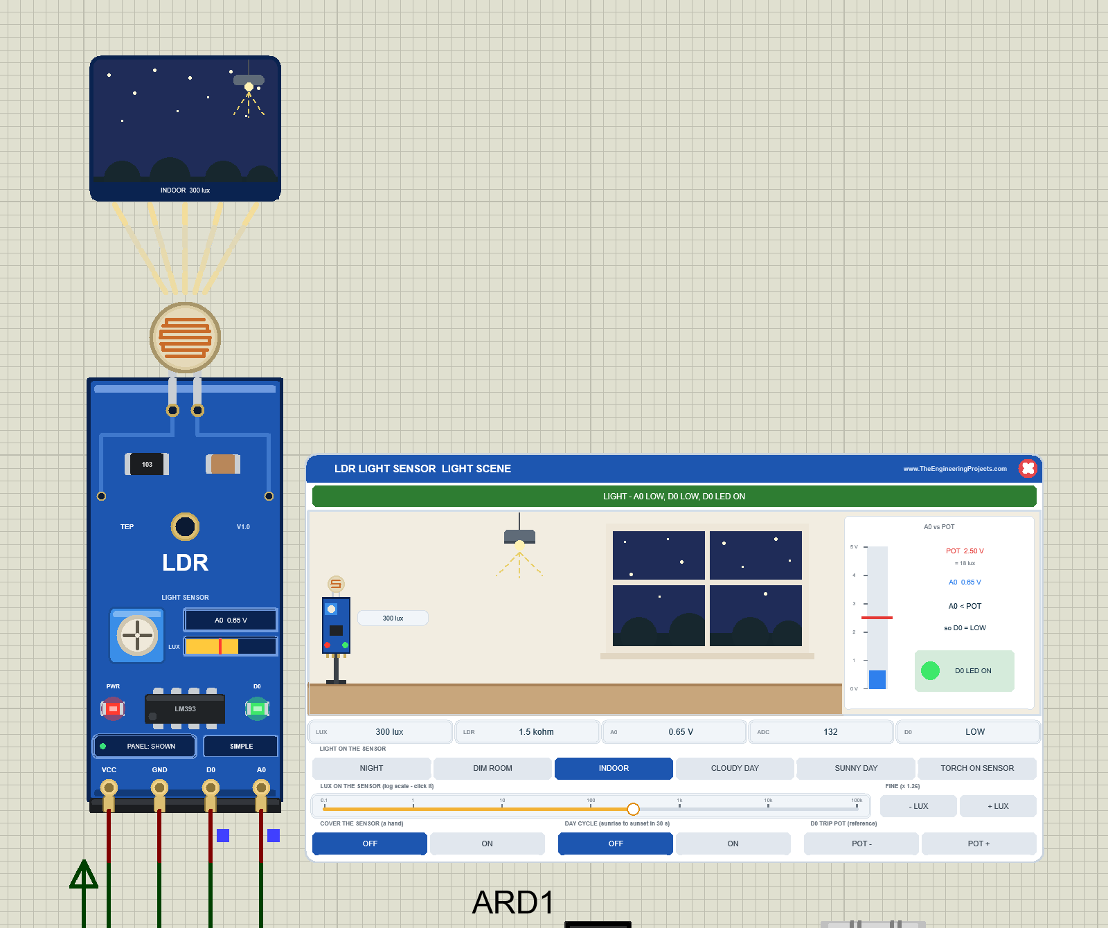
We drew the sensor as a clean TEP board in the blue of the real module and in its real proportions (about 31 x 14 mm, portrait): the 5 mm LDR with its orange zig-zag track on short legs over the top edge, the "103" 10 k resistor and a capacitor, a gold mounting hole, the blue pot, the LM393, the PWR and D0 LEDs and the 4-pin header. Here is U1, the Simple device, at the start (INDOOR, 300 lux), with its panel:
The Board Animation
While the simulation runs, the board shows what the sensor sees:
- The "what the sensor sees" window above the LDR: the night with the moon, a dusk, the evening with the room lamp (here "INDOOR 300 lux"), clouds, the sun, the torch or the hand, with the light in lux.
- Five light beams fall onto the LDR, coloured by the light; a ripple runs down them while the light changes.
- The LDR's face glows in light and turns dark at night, and the pot's rotor turns with the trip level.
Pinout
The four pins sit in the order most boards print on the header:
| Pin | What it does | Demo connection |
|---|---|---|
| VCC | Power, 3.3 to 5 V | Supply terminal (5 V) |
| GND | Ground | GND |
| D0 | Digital output: LOW in light, HIGH in the dark | Arduino A1 (used as a digital input) |
| A0 | Analog output: higher = darker | Arduino A0 |
LEDs and Indicators
| Indicator | What it shows |
|---|---|
| PWR LED (red) | Lit while the board has power |
| D0 LED (green) | Lit while D0 is LOW, so in light |
| "What the sensor sees" window | The sky or the light source, with the lux |
| Light beams | The light falling onto the LDR |
| LUX bar | The demo sketch's lux on a log scale, with the pot's trip light as a red mark |
| A0 box | The live A0 voltage |
| PANEL / OPEN PANEL, SIMPLE / ADVANCE | The panel button and the device badge |
The PWR and D0 LEDs are the real module's own. The window, the beams, the LUX bar and the A0 box are TEP additions: the real board has no display.
Component Properties
| Property | Meaning | Default |
|---|---|---|
| LIGHT | The light at the start: NIGHT, DIM ROOM, INDOOR, CLOUDY DAY, SUNNY DAY, TORCH, or a number of lux from 0.1 to 100000 | INDOOR |
| COVER | A hand over the sensor, YES or NO | NO |
| DAYCYCLE | The day cycle, ON or OFF | OFF |
| THRESHOLD | The D0 pot: the reference in % of VCC, 5 to 95 (50 = about 18 lux) | 50 |
| PANEL | Simple only: the panel at the start, OPEN or CLOSED | OPEN |
Every Run starts from these properties, with the LDR already settled (no lag at the start). The panel's clicks last until the simulation stops. The panel style comes from the device (Simple or Advance), not from a property.
LDR Simple: The Light Scene Panel on the Sheet
Beside the Simple board sits the LDR LIGHT SENSOR LIGHT SCENE panel (on the right of the image above):
| Part | What it does |
|---|---|
| Header, red X | The title and our website; the X closes the panel |
| Status banner | LIGHT, DARK, HAND OVER THE SENSOR, TORCH ON THE SENSOR or NO POWER, with what A0, D0 and the D0 LED do |
| The room | A window with the sky, a ceiling lamp, the sensor on a stand with a lux tag, and a torch or a hand when you use them |
| A0 vs POT | A 0 to 5 V gauge: A0 as a blue bar, the pot's reference as a red line, "A0 < POT, so D0 = LOW" and a D0 LED lamp |
| Readouts | LUX (what the demo sketch prints), LDR (its resistance), A0, ADC and D0 |
| LIGHT ON THE SENSOR | NIGHT, DIM ROOM, INDOOR, CLOUDY DAY, SUNNY DAY and TORCH ON SENSOR |
| LUX ON THE SENSOR | A log slider from 0.1 to 100k lux (click it), and FINE - LUX / + LUX (x 1.26 a click) |
| COVER, DAY CYCLE, POT | COVER THE SENSOR (a hand) OFF / ON, DAY CYCLE OFF / ON, and D0 TRIP POT: POT - / POT + (5 % steps) |
In the start image, INDOOR and both OFF buttons are lit. The lux tag in the room and the LUX readout both say 300 lux. The gauge shows A0 at 0.65 V, far below the pot's 2.50 V (the red line, "= 18 lux"), so D0 is LOW and the D0 LED is on.
NIGHT: A0 Climbs, D0 Goes HIGH
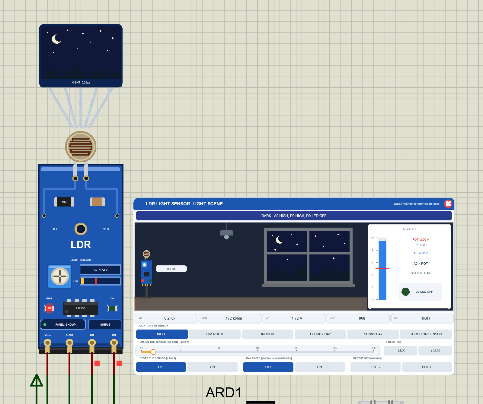
Click NIGHT. The window shows the moon and stars, the beams turn pale, the LDR's face goes dark and the room lamp goes off. The banner turns navy: "DARK - A0 HIGH, D0 HIGH, D0 LED OFF". The gauge shows A0 at 4.72 V, above the pot, so D0 is HIGH and the green D0 LED on the board is off.
Look at the readouts: LDR 172 kohm and ADC 968. That is not the end value yet: the LDR is still recovering from the room light and creeps on to about 188 kohm and ADC 972. The demo's night lamp comes on, and U3 shows the climb line by line; the README's example goes 946, 958, then "Light: about 0.2 lux ADC: 972 D0: HIGH Night - lamp ON".
COVER: A Hand Over the Sensor
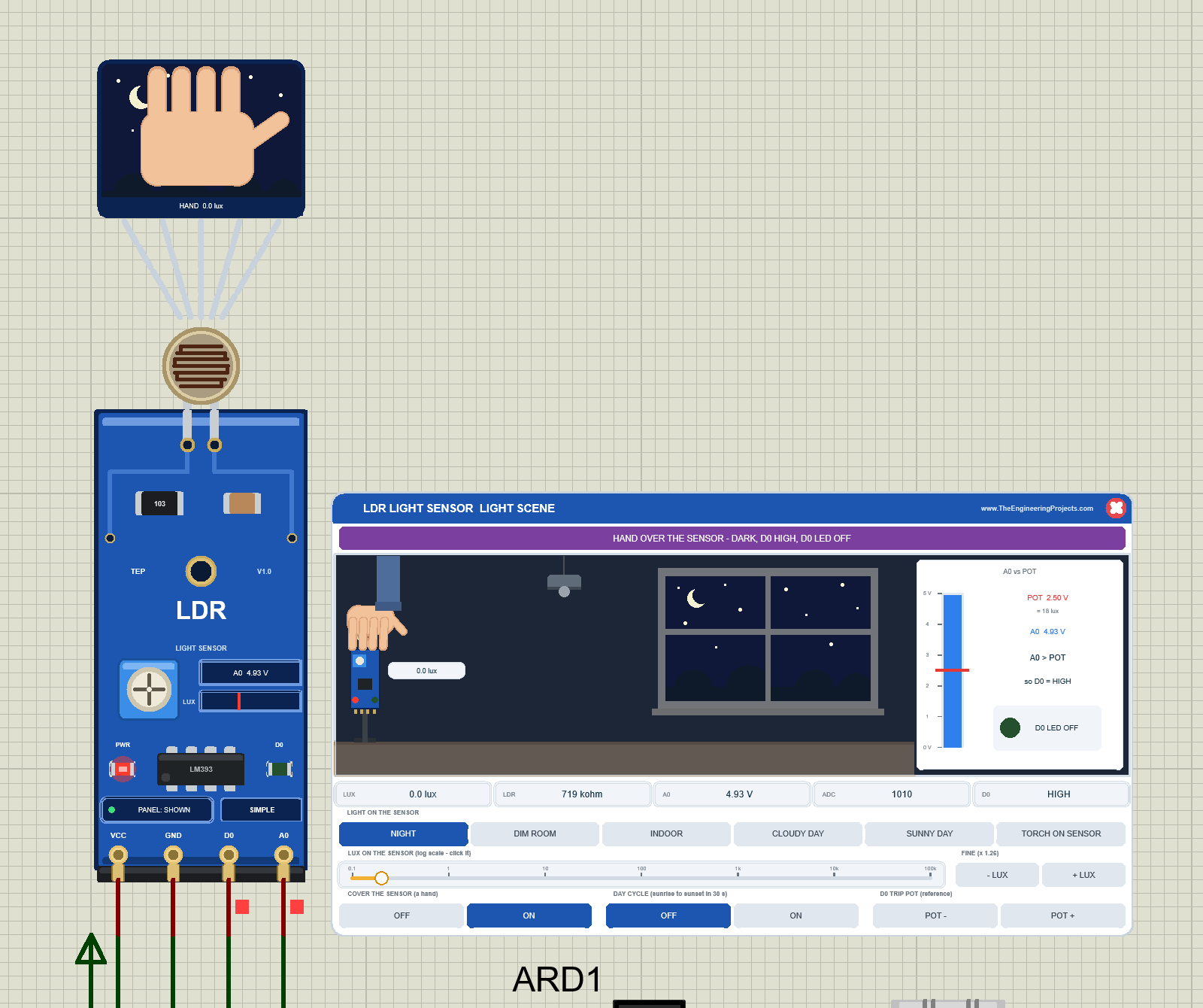
Click COVER ON: a hand comes down over the sensor, in the room and in the board's window. The hand lets 3 % of the light through. I did it at night here, so almost no light is left ("0.0 lux"), the LDR climbs to 719 kohm and the ADC to 1010, and the banner turns purple: "HAND OVER THE SENSOR - DARK, D0 HIGH, D0 LED OFF".
The classic test is a hand over the sensor in a lit room: INDOOR with COVER ON gives about 9 lux and ADC 630, darker than the pot's 18 lux, so D0 goes HIGH and the night lamp comes on. In direct sunlight, 3 % is still 1500 lux, so a hand does not make it dark.
DAY CYCLE: Sunrise to Sunset in 30 Seconds
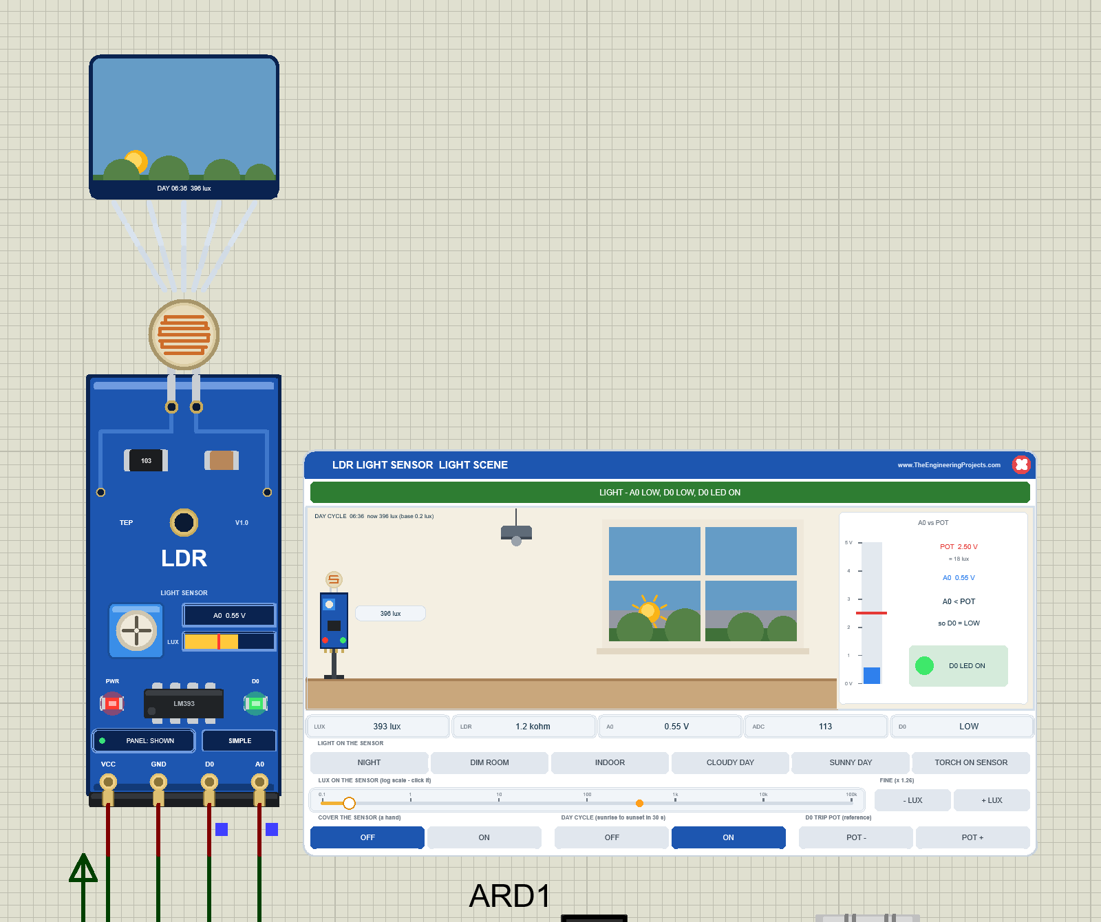
Click DAY CYCLE ON: a whole day passes every 30 s, from sunrise (06:00) through noon (50000 lux) to sunset (18:00) and the night. In the image it is 06:36: the sun rises over the hills, and D0 is already LOW.
The day cycle is an effect on top of the light you set. The LUX slider keeps your light, the base, with its white knob at 0.2 lux (NIGHT), and an amber dot marks the cycle's light now. The line at the top of the room says it in words: "DAY CYCLE 06:36 now 398 lux (base 0.2 lux)". No preset button is lit, because the light now comes from the cycle. Click DAY CYCLE OFF and the light goes back to the base.
At the middle pot, D0 is LOW (day) from 4.4 s to 25.6 s of each 30 s cycle, so the demo's night lamp goes off at sunrise and on again at sunset, on its own.
Closing the Panel
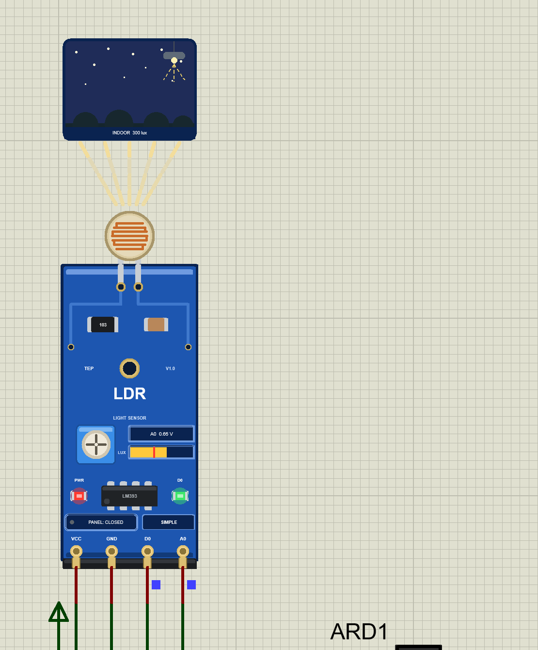
Click the red X: the board button says PANEL: CLOSED, and the sensor keeps running. PANEL brings the panel back. Here, U1 is at INDOOR again:
LDR Advance: The Pop-Up Sensor Window
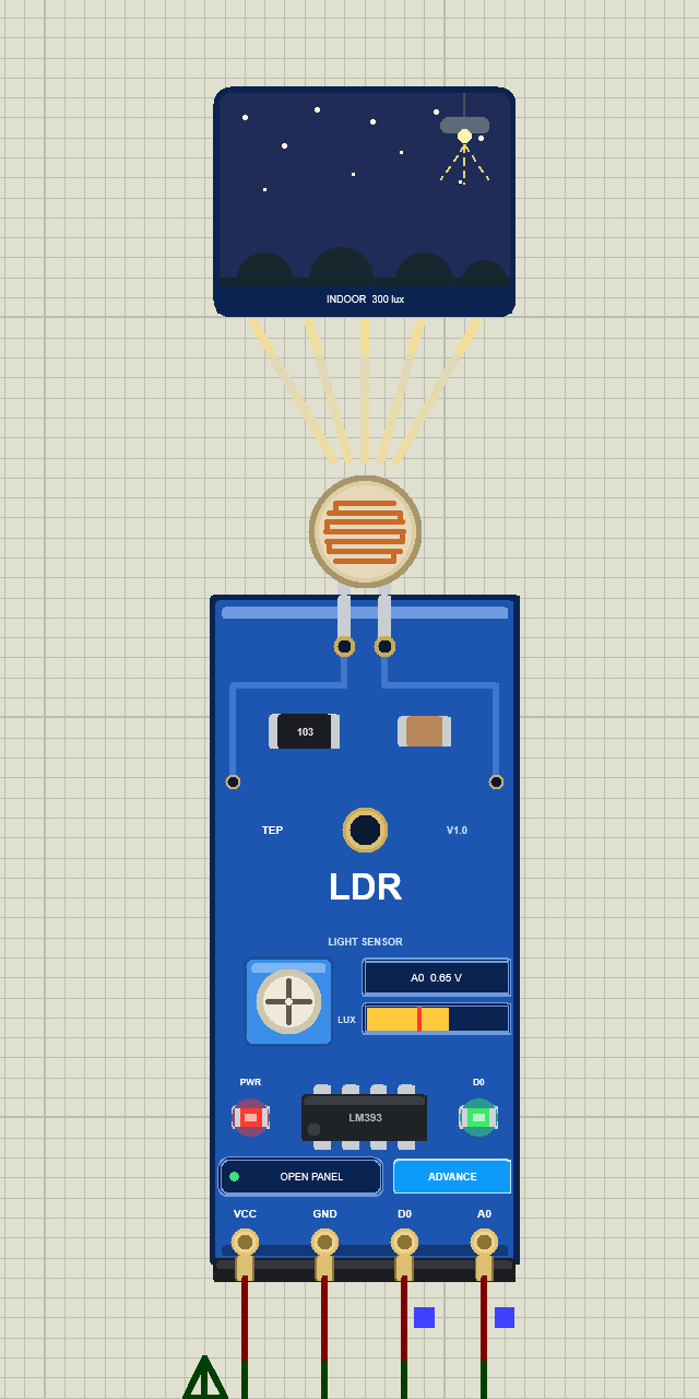
The Advance device keeps only the board on the schematic. Here is U2 at the start:
At Run, the "TEP LDR Sensor Advance" pop-up opens with the look of our TEP Serial Monitor and no Windows title bar: move it by its header, resize or minimise it, and reopen it with OPEN PANEL. The header shows the state (here U2 · LIGHT; it can also say DARK, HAND OVER, TORCH, TESTING or NO POWER), the Light and Test tabs, and the palette (theme), gear (Settings) and ? (Help) icons. The status bar at the bottom repeats it: Running, LDR U2, D0 LOW - light, A0 0.65 V, 300 lux.
The Light Page
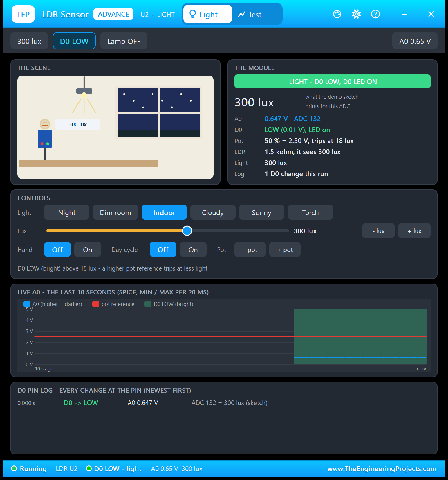
- Chips: 300 lux, D0 LOW, Lamp OFF (a night lamp that follows D0, like the demo's) and A0 0.65 V.
- THE MODULE: the lux the demo sketch prints for this ADC (300 lux), A0 0.647 V and ADC 132, D0 LOW (0.01 V) with its LED on, the pot (50 % = 2.50 V, trips at 18 lux) and the LDR (1.5 kohm, it sees 300 lux), next to the live scene.
- CONTROLS: the light presets, a lux slider with - lux / + lux, Hand, Day cycle and - pot / + pot. In the day cycle, the slider shows "(base)" with an amber "now" marker.
- LIVE A0 - THE LAST 10 SECONDS: A0 (minimum and maximum per 20 ms), the pot as a red line and the D0 LOW time shaded green. This run is only seconds old, so the trace fills just the right-hand part.
- D0 PIN LOG: every change of D0 with the time, A0 and the sketch's lux; here one entry at 0.000 s, "ADC 132 = 300 lux (sketch)".
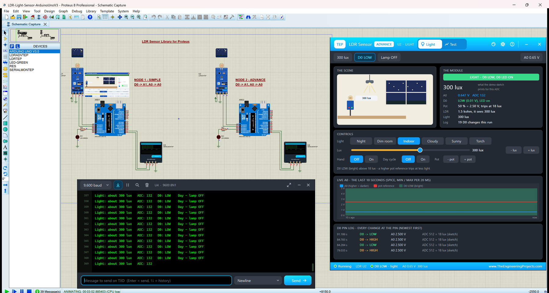
The featured image shows the same page after the test tools had run: 19 D0 changes, and the four newest log entries are the Night lamp tool's edges (HIGH at 79.035 s, LOW at 84.284 s, HIGH at 84.783 s, LOW at 91.186 s), every one at A0 2.500 V, ADC 512 = 18 lux, exactly at the pot.
The Test Page: Four Measured LDR Test Tools
The four tools on the Test tab take the light over (and put it back when they end) and measure the A0 and D0 node voltages of the running circuit at every simulation step. So every number is what the circuit really did, timed with the simulation clock. Each tool ends with a bold "Good for:" line. All results below come from U2, with the demo sketch running.
1. Light Sweep: What Does A0 Read From Moonlight to Sunlight?
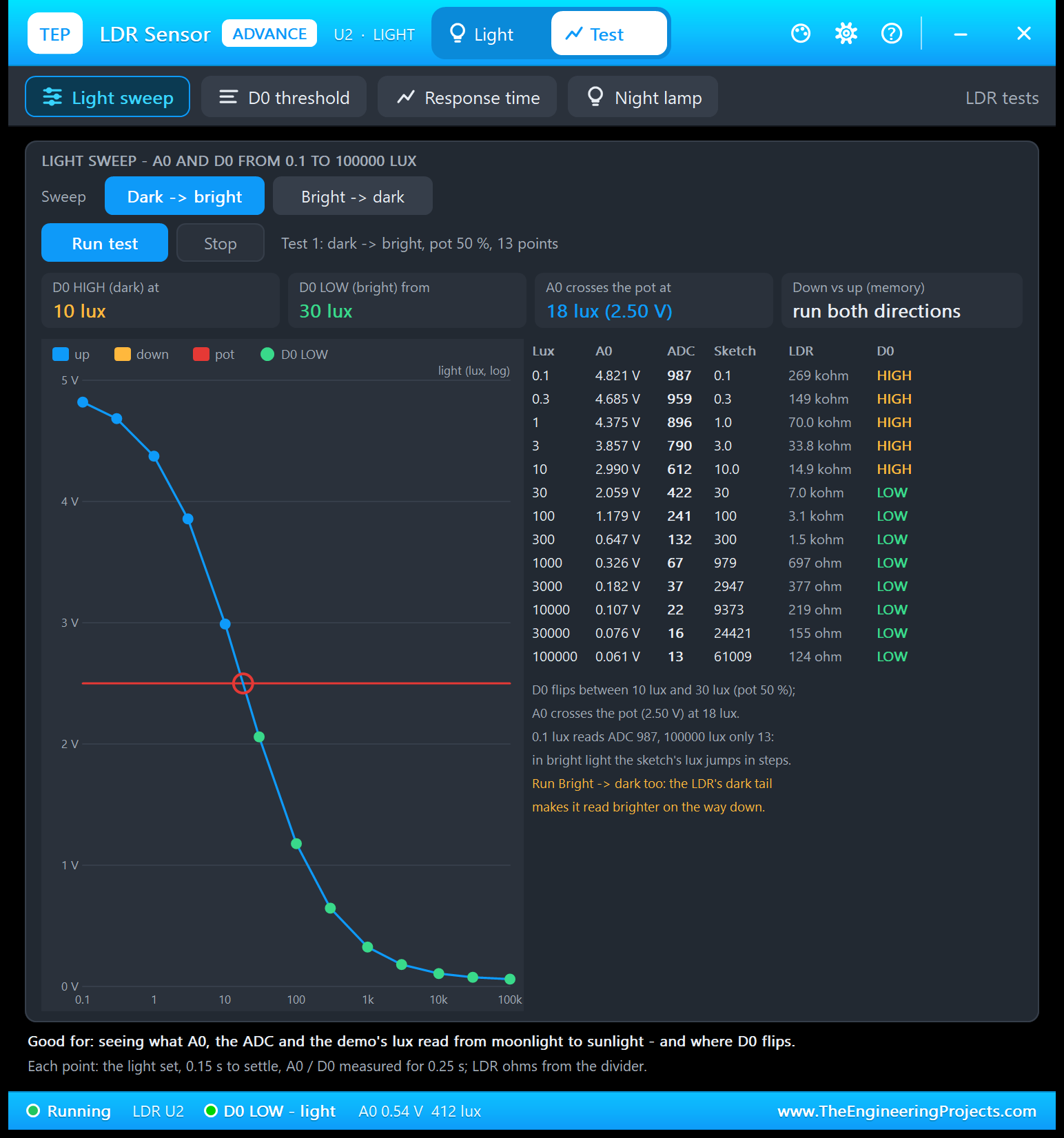
Good for: "seeing what A0, the ADC and the demo's lux read from moonlight to sunlight - and where D0 flips." The tool waits for a flat A0 at the first light (the dark tail needs a few seconds), then sets 13 lights from 0.1 to 100000 lux, half a decade apart: each one 0.15 s to settle and 0.25 s measuring. You choose the direction, dark to bright or bright to dark.
| Lux | A0 | ADC | Sketch | LDR | D0 |
|---|---|---|---|---|---|
| 0.1 | 4.821 V | 987 | 0.1 | 269 kohm | HIGH |
| 0.3 | 4.685 V | 959 | 0.3 | 149 kohm | HIGH |
| 1 | 4.375 V | 896 | 1.0 | 70.0 kohm | HIGH |
| 3 | 3.857 V | 790 | 3.0 | 33.8 kohm | HIGH |
| 10 | 2.990 V | 612 | 10.0 | 14.9 kohm | HIGH |
| 30 | 2.059 V | 422 | 30 | 7.0 kohm | LOW |
| 100 | 1.179 V | 241 | 100 | 3.1 kohm | LOW |
| 300 | 0.647 V | 132 | 300 | 1.5 kohm | LOW |
| 1000 | 0.326 V | 67 | 979 | 697 ohm | LOW |
| 3000 | 0.182 V | 37 | 2947 | 377 ohm | LOW |
| 10000 | 0.107 V | 22 | 9373 | 219 ohm | LOW |
| 30000 | 0.076 V | 16 | 24421 | 155 ohm | LOW |
| 100000 | 0.061 V | 13 | 61009 | 124 ohm | LOW |
D0 flips between 10 and 30 lux, and A0 crosses 2.50 V at 18 lux. Up to 300 lux, the sketch's lux matches the light. Above 1000 lux, the ADC is only a few counts, so one count is a big jump: the sketch prints 979 for 1000 lux and 61009 for 100000 lux. Run bright to dark too: the dark tail makes the LDR read brighter on the way down (on the PC, the crossing moved to 15 lux).
2. D0 Threshold: Where Does the LM393 Switch?
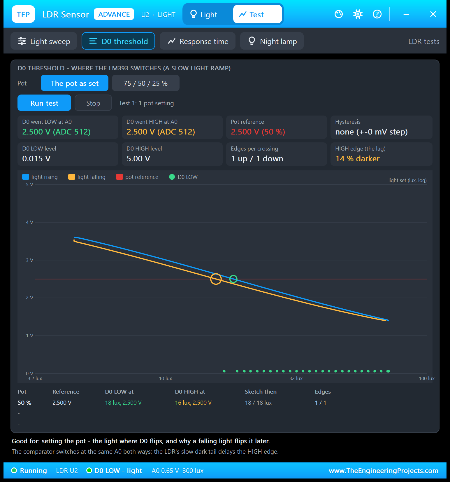
Good for: "setting the pot - the light where D0 flips, and why a falling light flips it later." The tool ramps the light slowly (0.4 decades a second) from a quarter of the pot's light to four times it and back, at the pot as set or at 75 / 50 / 25 %. The results:
- D0 went LOW at A0 2.500 V (ADC 512) and went HIGH at 2.500 V (ADC 512): the LM393 switches at the pot's reference, 2.500 V (50 %), both ways.
- Hysteresis: none (+-0 mV step).
- D0 levels: 0.015 V LOW and 5.00 V HIGH, from the LM393's open collector and the 10 k pull-up.
- Edges per crossing: 1 up / 1 down: D0 switched cleanly, with no chatter on the slow ramp.
- HIGH edge (the lag): 14 % darker. The table below the chart says why: D0 went LOW at 18 lux on the way up, but HIGH only at 16 lux on the way down.
So the voltage is the same both ways, but the light is not: on the way down, the slow LDR still "remembers" more light. It works like a small hysteresis, but it comes from the LDR, not from the board. The sketch printed 18 lux at both edges, because it saw ADC 512 both times. "75 / 50 / 25 %" runs three pot settings (on the PC: 3.7, 18 and 91 lux).
3. Response Time: How Fast Is the LDR?
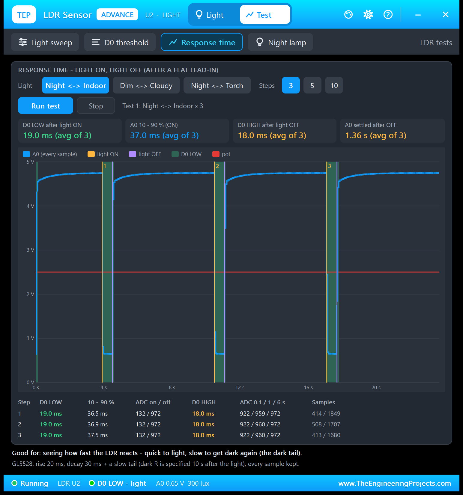
Good for: "seeing how fast the LDR reacts - quick to light, slow to get dark again (the dark tail)." Choose the lights (Night / Indoor, Dim room / Cloudy or Night / Torch) and 3, 5 or 10 steps. The tool waits for a flat A0 in the dark, then switches the light on for 0.6 s and off for 6 s, keeping every sample.
| Step | D0 LOW | 10 - 90 % | ADC on / off | D0 HIGH | ADC 0.1 / 1 / 6 s | Samples |
|---|---|---|---|---|---|---|
| 1 | 19.0 ms | 36.5 ms | 132 / 972 | 18.0 ms | 922 / 959 / 972 | 414 / 1849 |
| 2 | 19.0 ms | 36.9 ms | 132 / 972 | 18.0 ms | 922 / 960 / 972 | 508 / 1707 |
| 3 | 19.0 ms | 37.5 ms | 132 / 972 | 18.0 ms | 922 / 960 / 972 | 413 / 1680 |
When the light comes on, D0 goes LOW after 19.0 ms, and A0 covers 10 to 90 % of its way in about 37 ms. When the light goes off, D0 is HIGH again after 18.0 ms, because the first 85 % of the recovery is fast. The rest is slow: the ADC is 922 after 0.1 s, about 960 after 1 s, and 972 (the night value) only after 6 s; on average, A0 counted as settled after 1.36 s. In the chart, the blue A0 trace drops at each light-on, inside its green D0 LOW band, and climbs back in a long curve.
4. Night Lamp: When Does the Lamp Switch?
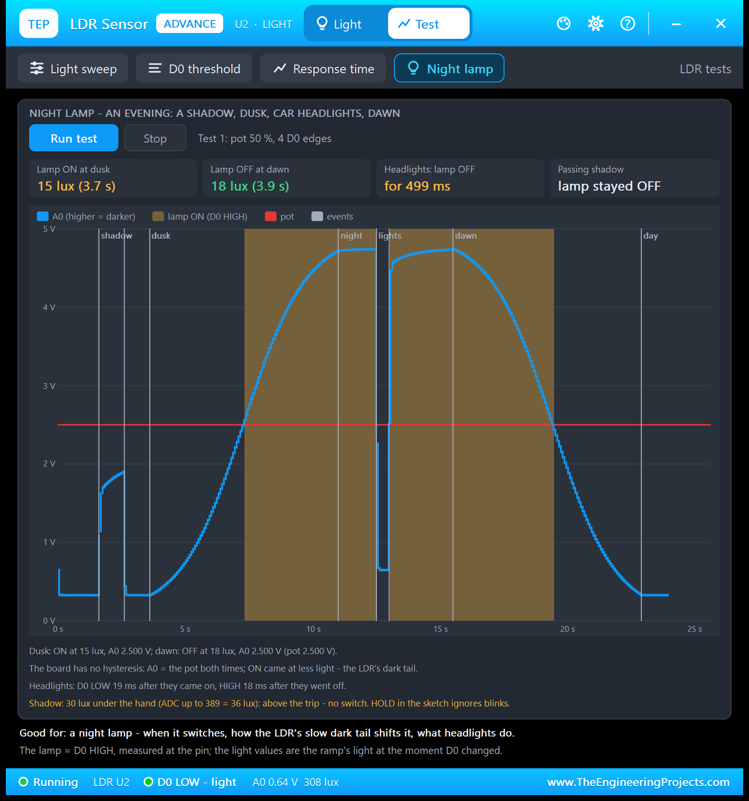
Good for: "a night lamp - when it switches, how the LDR's slow dark tail shifts it, what headlights do." The tool plays a 25 s evening at the pot as set: day (1000 lux), a passing shadow (a hand, 1 s), dusk (0.5 decades a second down to 0.2 lux), car headlights at night (300 lux for 0.5 s) and dawn. The lamp is D0 HIGH, as in the demo sketch, measured at the pin; the brown bands in the chart are the lamp ON.
- Lamp ON at dusk: 15 lux, 3.7 s into the dusk, at A0 2.500 V.
- Lamp OFF at dawn: 18 lux, 3.9 s into the dawn, also at A0 2.500 V.
- Headlights: D0 LOW 19 ms after they came on and HIGH 18 ms after they went off, so the lamp was OFF for 499 ms.
- Passing shadow: 30 lux under the hand (ADC up to 389 = 36 lux), still above the trip, so the lamp stayed OFF.
The board has no hysteresis, and A0 equals the pot at both switching points. Still, the lamp comes on at less light (15 lux) than it goes off (18 lux), because of the LDR's dark tail. The headlights show the weak point of a simple night lamp: half a second of light switches it off. The demo sketch's HOLD command fixes that.
Settings and Help
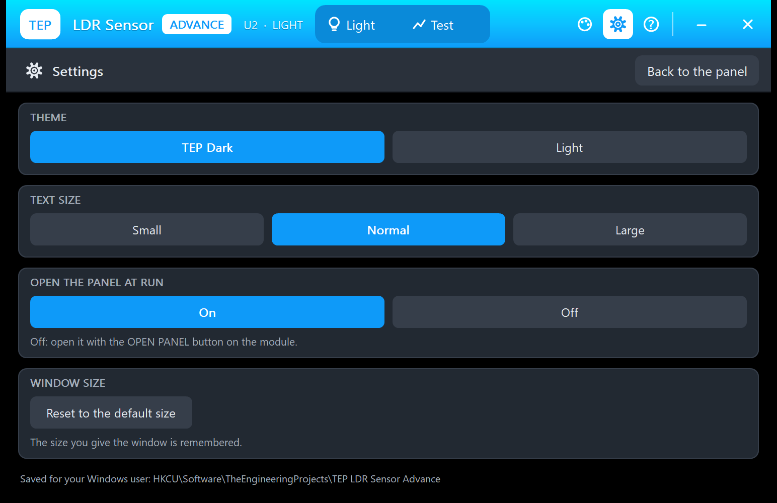
The gear opens Settings: theme (TEP Dark or Light), text size (Small, Normal or Large), open the panel at Run (On or Off; with Off, you open it with OPEN PANEL), and a button that resets the window size. Everything is saved for your Windows user.
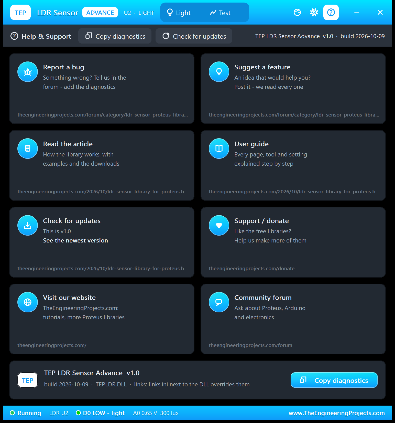
The ? icon opens Help & Support: eight cards with their links (the LDR forum board for bugs and ideas, this article, updates, donate, website, forum), Check for updates, and Copy diagnostics for a bug report: the sensor, the scene, the board, the D0 log and the test results. A links.ini next to the DLL can change the links.
LDR Night Lamp with Arduino in Proteus
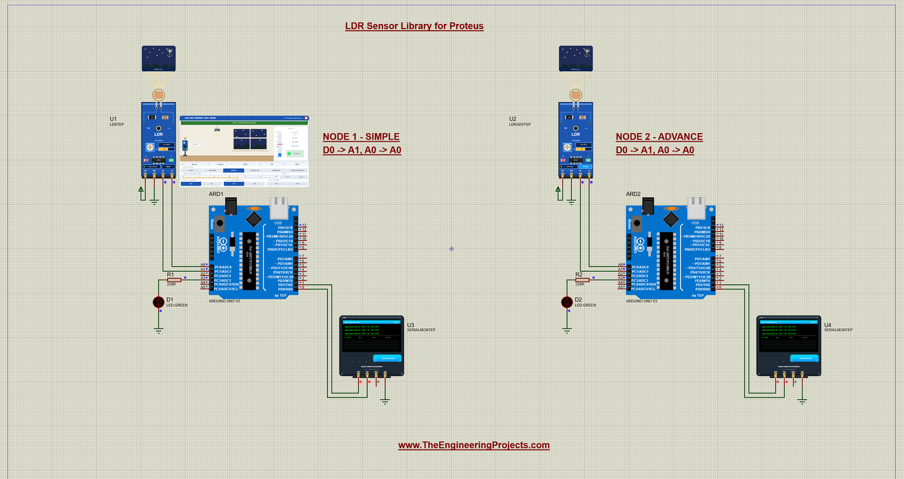
Open LDR-Light-Sensor-ArduinoUnoV3.pdsprj from the Proteus Simulation folder, with LDR_Night_Lamp.hex and both DLLs beside it. Its two Arduino UNOs from our Arduino Library for Proteus V3.0 run the same HEX file:
- NODE 1 - SIMPLE: UNO 1 (ARD1) with the LDR Simple (U1), the lamp LED D1 on A3 and Serial Monitor U3.
- NODE 2 - ADVANCE: UNO 2 (ARD2) with the LDR Advance (U2), the lamp LED D2 on A3 and Serial Monitor U4.
Wiring
| From | To | Why |
|---|---|---|
| LDR VCC / GND | Supply terminal / ground | Power (the PWR LED lights) |
| LDR A0 | Arduino A0 | The analog reading |
| LDR D0 | Arduino A1 | The digital output; A1 works as a normal digital input |
| LED + 220 ohm | A3 to GND | The night lamp (the UNO's own LED on D13 does the same) |
| Serial Monitor RXD / TXD / GND | Arduino D1 / D0 / ground | Shows what the Arduino prints, sends what you type |
| Serial Monitor RXD2 | Not connected | The sensor has no serial line to watch |
Why A1 for D0? In the demo, the sensor sits left of the UNO, and A0 and A1 are both on the UNO's left edge, so the wires do not cross. On your own board, D2 or any other digital pin works the same: change SENSOR_D0 in the sketch. See our Introduction to Arduino UNO for the pins.
The Arduino Code
The sketch needs no extra library. First, the pins:
const int SENSOR_A0 = A0;     // analog output of the sensor board
const int SENSOR_D0 = A1;     // digital output of the sensor board (used as a digital input)
const int LAMP = 13;          // the night lamp (the UNO's on-board LED)
const int LAMP2 = A3;         // the demo's lamp LED (+ 220 ohm to GND)
Then the board's divider and the GL5528 curve, for the lux estimate:
const float PULL_UP = 10000.0;     // the board's resistor from VCC to A0 (ohms)
const float R_FLOOR = 100.0;       // the LDR's contacts: the part that does not change with light (ohms)
const float R_DARK = 1000000.0;    // the LDR in the dark (ohms)
const float R10 = 15000.0;         // the LDR at 10 lux (ohms)
const float GAMMA = 0.7;           // how fast the LDR's resistance falls with light
setup() prints three start lines:
void setup() {
  Serial.begin(9600);
  pinMode(SENSOR_D0, INPUT);
  pinMode(LAMP, OUTPUT);
  pinMode(LAMP2, OUTPUT);
  Serial.println("LDR Light Sensor Night Lamp - The Engineering Projects");
  Serial.println("Reading A0 and D0 every 0.5 s...");
  Serial.println("LDR Sensor Library for Proteus - type HELP for the commands");
}
The loop never calls delay(). It checks the lamp every 10 ms and takes a reading every 500 ms, so typed commands are answered at once:
void loop() {
  readCommands();
  unsigned long now = millis();
  if (now - lastCheck >= 10) {                     // the lamp decision every 10 ms (no delay(): commands stay quick)
    lastCheck = now;
    updateLamp(now);
  }
  if (everyMs > 0 && now - lastRead >= everyMs) {
    lastRead = now;
    takeReading();
  }
}
The lux estimate: the ADC count gives A0 / VCC (the middle of the ADC step), the divider gives the LDR's resistance, and the GL5528 curve, turned around, gives the lux:
float luxFromAdc(int adc) {
  if (adc >= 1023) return 0.0;                    // 5 V: completely dark
  float ratio = (adc + 0.5) / 1024.0;              // A0 / VCC (the middle of the ADC step)
  float rLdr = PULL_UP * ratio / (1.0 - ratio) - R_FLOOR;   // the LDR's light-dependent part
  if (rLdr <= 1.0) return 100000.0;                // (almost) 0 V: blinding light
  float g = 1.0 / rLdr - 1.0 / R_DARK;             // its conductance without the dark part
  if (g <= 0) return 0.0;
  float lux = 10.0 * pow(g * R10, 1.0 / GAMMA);
  return lux > 100000.0 ? 100000.0 : lux;
}
The lamp follows D0, because the board's comparator has already decided; after LAMP A0, it compares the ADC with your own level instead. HOLD makes it wait until the light has stayed changed for holdMs:
void updateLamp(unsigned long now) {
  bool want;
  if (lampAdc > 0) want = analogRead(SENSOR_A0) > lampAdc;
  else want = digitalRead(SENSOR_D0) == HIGH;      // the board's comparator already decided for us
  if (want == lampOn) { pending = false; return; }
  if (!pending) { pending = true; changeSince = now; }
  if (now - changeSince >= holdMs) {
    pending = false;
    lampOn = want;
    switches++;
    digitalWrite(LAMP, lampOn ? HIGH : LOW);
    digitalWrite(LAMP2, lampOn ? HIGH : LOW);
  }
}
Each reading prints one line. "LOW " gets a trailing space, so the columns stay aligned:
  Serial.print("Light: about ");
  printLux(lux);
  Serial.print(" lux   ADC: ");
  Serial.print(adc);
  Serial.print("   D0: ");
  Serial.print(d0 == HIGH ? "HIGH" : "LOW ");
  Serial.print("   ");
  // (Without D0 you could compare the reading instead: LAMP A0 600 = darker than about 10 lux.)
  if (lampOn) Serial.println("Night - lamp ON");
  else Serial.println("Day - lamp OFF");
HELP prints two lines, short enough for the Serial Monitor's Simple interface:
  if (isCommand("HELP")) {
    Serial.println("Commands: HELP, STATUS, READ, EVERY ms (0 = pause),");
    Serial.println("  LAMP D0, LAMP A0 adc (lamp ON above adc), HOLD ms (0 - 10000)");
LAMP A0 takes the lamp away from D0 and gives it your own ADC level; the answer uses luxFromAdc() to tell you how dark that level is:
    } else if (strncmp(cmd, "LAMP A0 ", 8) == 0 && number() >= 1 && number() <= 1022) {
      lampAdc = number();
      Serial.print("The lamp is ON while the ADC is above ");
      Serial.print(lampAdc);
      Serial.print(" (darker than about ");
      printLux(luxFromAdc(lampAdc));
      Serial.println(" lux)");
And HOLD, the fix for car headlights:
  } else if (isCommand("HOLD")) {
    long ms = number();
    if (ms >= 0 && ms <= 10000) {
      holdMs = ms;
      if (holdMs == 0) Serial.println("HOLD 0: the lamp switches at once");
      else {
        Serial.print("The lamp waits ");
        Serial.print(holdMs);
        Serial.println(" ms before it switches (it ignores headlights)");
      }
The settings live in RAM, so a new Run starts again with a reading every 500 ms, LAMP D0 and HOLD 0. To change the sketch, export a new HEX file and load it into both UNOs; see How to get the HEX file from Arduino. New to Arduino? Start with our Arduino Tutorial for Beginners.
Serial Monitor Commands
| Command | What it does |
|---|---|
| HELP | The command list (two lines) |
| STATUS | Two lines: the interval, the lamp mode and HOLD; then the last reading, the lamp, its switches and the number of readings |
| READ | One reading now |
| EVERY ms | The reading interval, 100 to 10000 ms (0 = pause) |
| LAMP D0 | The lamp follows D0, so the board's pot (the default) |
| LAMP A0 adc | The lamp is ON while the ADC is above adc (1 to 1022); LAMP A0 600 means darker than about 10 lux |
| HOLD ms | The lamp switches only after the light stayed changed this long (0 to 10000 ms); HOLD 1000 ignores headlights |
How to Run the Demo
- Press Run. Both Serial Monitors (9600 baud) and U2's pop-up open; both sensors start at INDOOR.
- On U1's panel, click NIGHT and watch the readings creep up and the lamp come on; then try the other presets, the LUX slider, COVER ON, DAY CYCLE ON and POT - / POT +.
- Click STATUS on U3, then HOLD 1000 and LAMP A0 600; LAMP D0 goes back to the pot.
- On U2, try the Light page and the four tools on the Test tab, while U4 shows what your sketch reads.
- Close U2's window and reopen it with OPEN PANEL; close U1's panel with its red X and reopen it with PANEL.
LDR Proteus Simulation Results
The Serial Monitor in Its Simple Interface
Both monitors in this demo run in the Simple interface of our TEP Serial Monitor, as in every monitor screenshot here. Only the log, the send box and one slim toolbar row stay visible (baud rate, follow, pause, search and clear), so the window stays small.
- Switch to it: right-click the log and choose Simple interface, or press Ctrl+Shift+U.
- Back to the full view: click the corner button (the expand arrows at the top right), press Esc or Ctrl+Shift+U, or right-click and choose Full interface.
- Your choice is remembered.
Type commands in the send box and press Enter; the quick buttons come back with the full view. Every line the sketch prints is shorter than 80 characters. Read all about the monitor in TEP Serial Monitor Advance for Proteus.
Start-Up
After Run, U3 prints the three start lines and then a reading twice a second:
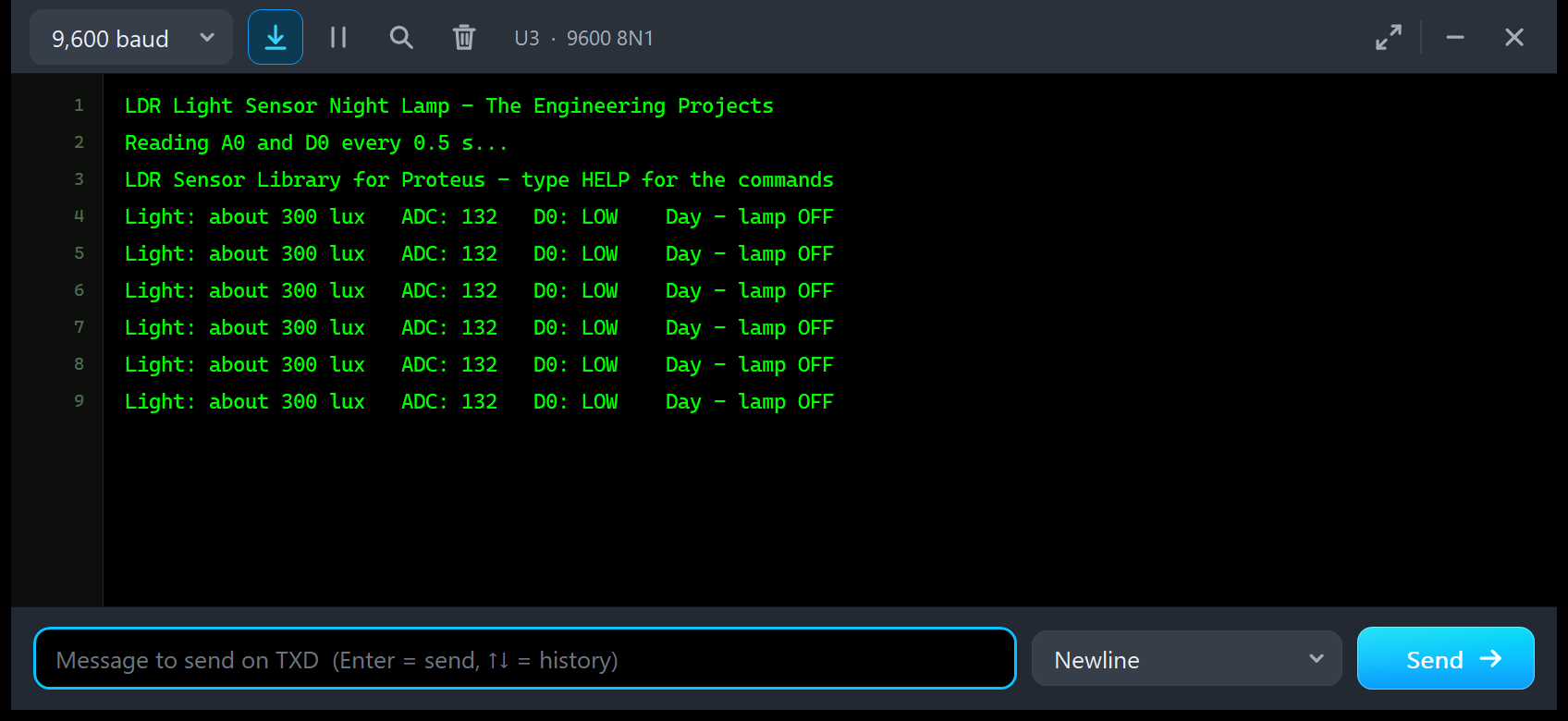
LDR Light Sensor Night Lamp - The Engineering Projects
Reading A0 and D0 every 0.5 s...
LDR Sensor Library for Proteus - type HELP for the commands
Light: about 300 lux   ADC: 132   D0: LOW    Day - lamp OFF
Light: about 300 lux   ADC: 132   D0: LOW    Day - lamp OFF
Light: about 300 lux   ADC: 132   D0: LOW    Day - lamp OFF
Light: about 300 lux   ADC: 132   D0: LOW    Day - lamp OFF
Light: about 300 lux   ADC: 132   D0: LOW    Day - lamp OFF
Light: about 300 lux   ADC: 132   D0: LOW    Day - lamp OFF
This matches U2's pop-up exactly: 300 lux and ADC 132. The panels compute the ADC the way Proteus's UNO converts (1024 x A0 / 5 V, rounded to the nearest count) and the lux with the sketch's own formula, so the panel and the Serial Monitor print the same numbers. U4 prints the same lines; you can see them in the featured image.
STATUS and the Headlights
At NIGHT, type STATUS. The sketch answers with two lines; the README's example is "Status: every 500 ms, lamp follows D0, HOLD 0 ms" and "last: 0.2 lux, ADC 972, D0 HIGH, lamp ON, 1 switches, 24 readings" (the counts depend on how long it ran). Then click INDOOR and NIGHT again quickly: the lamp goes off for a moment, like with car headlights. Type HOLD 1000, and the sketch answers "The lamp waits 1000 ms before it switches (it ignores headlights)"; now a flash shorter than a second no longer switches the lamp.
Troubleshooting
- The lamp stays on in a lit room: the light is below the pot's level. Click POT - (a lower reference) or give more light; the A0 vs POT gauge shows A0 against the pot.
- After switching the light off, the ADC keeps creeping up for a few seconds: that is the LDR's slow dark recovery, as on a real LDR, not a bug.
- The lamp blinks when a light flashes at night: the board has no hysteresis, and the demo's lamp follows D0; type HOLD 1000.
- The lux the sketch prints jumps in big steps in bright light: A0 is only a few counts there, so the lux estimate is rough by nature.
- The panel's ADC and the sketch's ADC differ by a count while the light changes: each shows its own moment. Both round to the nearest count, as Proteus's UNO does; a real UNO truncates, so it may read one count lower.
- The part is not simulated, no panel or no monitor window: TEPLDR.DLL or TEPSERIALMON.DLL is missing from MODELS and from the project folder; click OPEN MONITOR on a closed monitor.
- The Advance pop-up does not appear: click OPEN PANEL on the board, or turn "Open the panel at Run" back on in Settings.
- Your own sketch waits for D0 with a pin-change interrupt and nothing happens: Proteus 8.5's ATmega328P does not run pin-change interrupts. Read D0 with
digitalRead(), as the demo does, or useattachInterrupt()on D2 (INT0).
Things to Know Before Using a Real LDR Module
The demo sketch uses only the Arduino core, so it runs on a real UNO and LDR module, too. Keep in mind:
- Supply: 3.3 to 5 V. A0 and the pot's reference follow VCC (they are ratiometric).
- Polarity: on almost every board, D0 is LOW in light (the D0 LED lights in light), and A0 is higher in the dark.
- Other versions: the 3-pin board (VCC, GND, DO) is the same board without A0. The KY-018 (only an LDR and a resistor) is a different part and reads the other way round.
- The pot: the middle position is about 18 lux, a dim room; on most boards, clockwise makes D0 say "light" already at less light.
- No hysteresis: with the light right at the pot's level, D0 can chatter; a fluorescent lamp's flicker does it. Let the sketch wait (HOLD).
- Real LDRs vary a lot (8 to 20 k at 10 lux) and drift with temperature, so treat the lux estimate as rough. A light meter needs a photodiode sensor; see our BH1750 Light Sensor Library for Proteus.
Limitations of the Simulation
- Modelled: the A0 divider, the LM393's D0 (no hysteresis), the PWR LED's load, the supply (3.3 to 5 V; nothing without it), the GL5528's curve and slow response, the hand, the day cycle and the pot.
- Not modelled: the LDR's temperature drift and its light memory (its history), its colour response, a fluorescent lamp's flicker, the 3-pin version, and the LM393's own delays (microseconds). The scene's values (0.2 lux at night, 3 % under the hand, and so on) are model values.
- The model is our own implementation, written from the module's published descriptions and the GL5528 data sheet. The HEX file contains the Arduino AVR core 1.8.6, which includes LGPL-licensed code; its source code is on GitHub.
- Tested in Proteus 8.5 in October 2026 (the demo as shipped, both UNOs, the Serial Monitors, the panel, the Advance window, the four tools and every screenshot here) and with 2,299 automatic PC checks, all passed, 26 of them with the real demo sketch on two UNOs. After that Proteus run, one change was made, for speed only: the Advance window now repaints at most 5 times a second (at once after a click in it). The model, the panels and every number are unchanged (PC-tested). Proteus 7 is not supported.
The same kind of blue LM393 board with A0 and D0 also carries a flame sensor and a soil moisture probe: try our Flame Sensor Library for Proteus V2.0 and our Soil Moisture Sensor Library for Proteus V3.0.
So, that was all about the LDR Sensor Library for Proteus. I hope the light scene, the slow LDR, the night lamp commands and the four test tools make the LDR module much easier to understand, so your night lamp works the first time you wire a real module. If you use the LDR Sensor Library for Proteus in a project, please share your feedback in the comments or in our forum, and if you have any questions, ask in the comments and I will help you out. Till the next tutorial, take care and have fun!
Comments
0