


ItsyBitsy nRF52840 Library for Proteus: Bluetooth LE Simulation


Hello friends, I hope you all are doing great. Today, I am going to share the ItsyBitsy nRF52840 Library for Proteus, so you can run a Bluetooth LE simulation of Adafruit's ItsyBitsy nRF52840 Express. The ItsyBitsy is one of the smallest nRF52840 boards: 1.4 x 0.7 inches with a Raytac MDBT50Q module, native USB, 2 MB of flash, a red LED, a DotStar, a user switch and two rows of 14 pins. Our part is drawn at true scale from Adafruit's own board file, and it runs your Arduino sketch in Proteus 8.5 with Bluetooth LE to a phone.
ItsyBitsy nRF52840 Library for Proteus
Latest version: V1.0 (November 2026, this tutorial)
Helping Tools
- Laptop WiFi Monitor: a laptop on the Wi-Fi of your design: a browser, a TCP / UDP terminal and ping
- Mobile WiFi Monitor: a smartphone that opens the pages of your board and sends it commands
- Serial Monitor Advance: a serial terminal window for the UART of your board
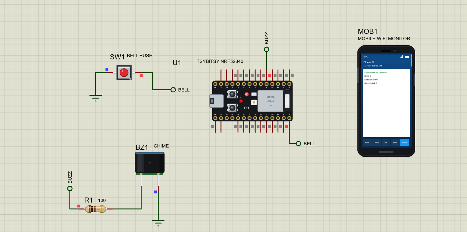
For the demo we built a Bluetooth doorbell: a bell push at the door, a two-tone chime and a phone that counts the visitors - with a do-not-disturb switch that keeps the chime quiet but still tells the phone.
NOTICE: Proteus has no nRF52840 model, so our team has put a lot of effort into building this board ourselves: the pins, the LED, the switch and Bluetooth LE to the phone are all our own model, and your sketch compiles with our free TEP Boards for Proteus add-on. Your feedback is the fuel that keeps us going, so please tell us what you think in the comments below. And if our free libraries help you, you can buy us a coffee. So, let's get started with the ItsyBitsy nRF52840 Library for Proteus:
What is the ItsyBitsy nRF52840 Express?
The ItsyBitsy nRF52840 Express is Adafruit's smallest Bluetooth board in its ItsyBitsy family: the size of a stick of gum, breadboard-friendly, and built around a Raytac MDBT50Q module with the nRF52840 (an Arm Cortex-M4F at 64 MHz with 1 MB of flash, 256 KB of RAM, Bluetooth LE and native USB). The module carries its own antenna at one end of the board, so nothing else is needed for the radio.
| Part | The real board | In the library |
|---|---|---|
| Module | Raytac MDBT50Q with the nRF52840 | your Arduino sketch, ArduinoBLE |
| Size | 1.4 x 0.7 in (35.56 x 17.78 mm) | drawn at true scale |
| Pins | two rows of 14 at 0.1 in | the same rows, the same order |
| LED | red, D3 (P0.06), active HIGH | LED_BUILTIN, lit when HIGH |
| Switch | SWITCH on D4 (P0.29) | PIN_BUTTON1, clickable |
| Pin 5 | a 5 V output through a buffer | an ordinary pin |
| DotStar | APA102 on D8 / D6 | drawn |
Drawn from Adafruit's Own Board File
Adafruit publishes the board's design files. We read the pin order straight from them: one row starts at the USB end with BAT, G, USB, 13, 12, 11, 10, 9, 7, 5, SCL, SDA, TX and RX; the other with RST, 3V, EN, Vhi, A0 to A5, SCK, MO, MI and 2. The buttons, the LED, the DotStar and the module sit where the real board has them, so a wiring diagram drawn on our part matches the real one.
ItsyBitsy or Feather?
The Feather nRF52840 Express has the same chip on a larger board with a battery charger and a JST socket; the ItsyBitsy trades those for size. See our Feather nRF52840 Express Library for Proteus for the bigger brother. A simulation is the cheapest way to decide which one a project needs.
Features of the ItsyBitsy nRF52840 Library for Proteus
- The board at true scale: the black PCB, the micro-USB, RESET, the SWITCH, the red LED, the DotStar, the crystal, the MDBT50Q module with its antenna end and the two rows of pins, with our small TEP signature.
- Your sketch: a .hex for "Adafruit ItsyBitsy nRF52840 Express (TEP Proteus)" with Adafruit's pin numbers.
- Bluetooth LE: ArduinoBLE with services, characteristics, descriptors and notifications; our Mobile WiFi Monitor is the phone.
- The serial monitor: a click on the micro-USB.
- A complete package: about 4.4 MB with the part, the add-on, the button, the buzzer, the resistor, the phone and the demo, without the source code of the models.
The ItsyBitsy nRF52840 in Proteus Simulation
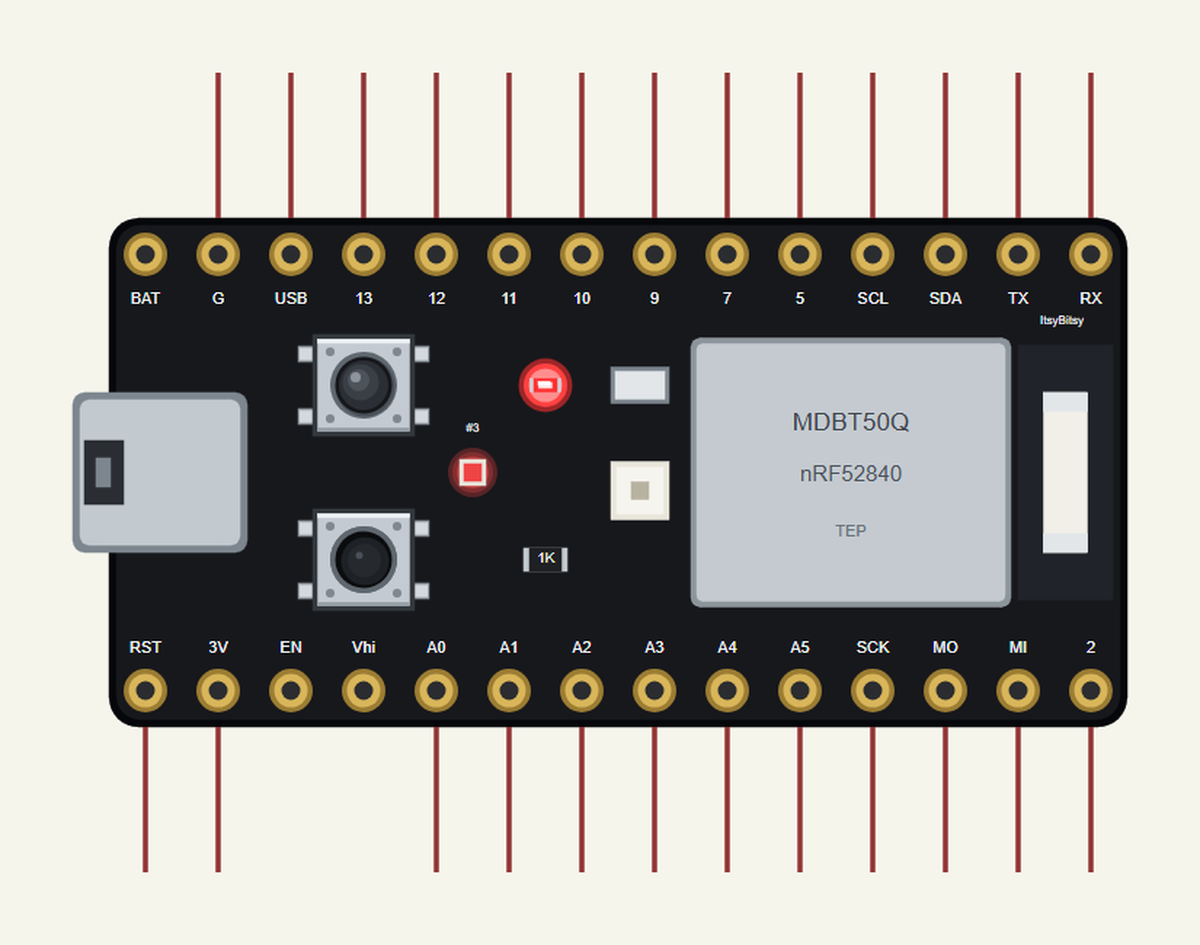
Search ITSYBITSY in Pick Devices; the device ITSYBITSY NRF52840 is in TEPITSY52.LIB (Microprocessor ICs, Bluetooth Boards), with the prefix U. The micro-USB opens the serial monitor.
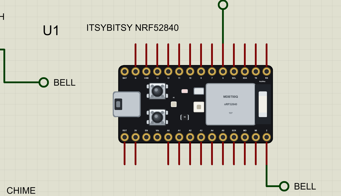
The Pins
| Pins | What the library does with them |
|---|---|
| RX, TX | D0 / D1: Serial1, or GPIO |
| 2, 5, 7, 9 to 13 | GPIO, PWM, interrupt, pulse timing |
| A0 to A5 | analogRead 0 to 1023 for 0 to 3.3 V, or GPIO |
| SDA, SCL | Wire |
| SCK, MO, MI | SPI |
| D3, D4 | the red LED (lit when HIGH) and the SWITCH (LOW when pressed), on the board |
Download ItsyBitsy nRF52840 Library for Proteus
Click the button below to download ItsyBitsy-nRF52840-Library-for-Proteus-v1.0.zip (about 4.4 MB, without the source code of the models):
ItsyBitsy nRF52840 Library for Proteus V1.0- README.txt: installation, the demo, the pins, the properties, troubleshooting and the limits.
- Proteus Library Files:
TEPITSY52.LIB, the button, the buzzer and the resistor (TEPBUTTON.LIB,TEPPASSIVE.LIB,TEPRESISTOR.LIB) and the phone and laptop. - Proteus Model Files:
TEPNET.DLL,TEPBUTTON.DLL,TEPPASSIVE.DLLandTEPRESISTOR.DLL. - Arduino Code: the demo sketch and the TEP Boards for Proteus add-on 1.92.0, with ArduinoBLE.
- Proteus Simulation: the demo project, its HEX file and copies of the DLLs.
No Proteus yet? Read How to Download and Install Proteus 7 and 8. New to libraries? Follow How to Install a New Library in Proteus.
How to Install ItsyBitsy nRF52840 Library for Proteus
- Close Proteus and extract the whole zip file, for example to your Desktop.
- Copy the files from Proteus Library Files into the LIBRARY folder of Proteus.
- Copy the DLLs from Proteus Model Files into the MODELS folder, replacing an older
TEPNET.DLL. - Delete
TEPITSY52.IDXfrom the LIBRARY folder if it is there. - For your own sketches, copy Arduino Code\TEP Boards for Proteus\hardware into your Arduino sketchbook (Documents\Arduino) and restart the Arduino IDE; the board is Adafruit ItsyBitsy nRF52840 Express (TEP Proteus).
- Start Proteus, press P and search for ITSYBITSY.
Demo: a Bluetooth Doorbell in Simulation
A wireless doorbell is a classic first Bluetooth project: one press at the door, a chime inside, and - with a phone - a record of every visitor while you were out in the garden. The ItsyBitsy is small enough to sit behind the bell push itself.
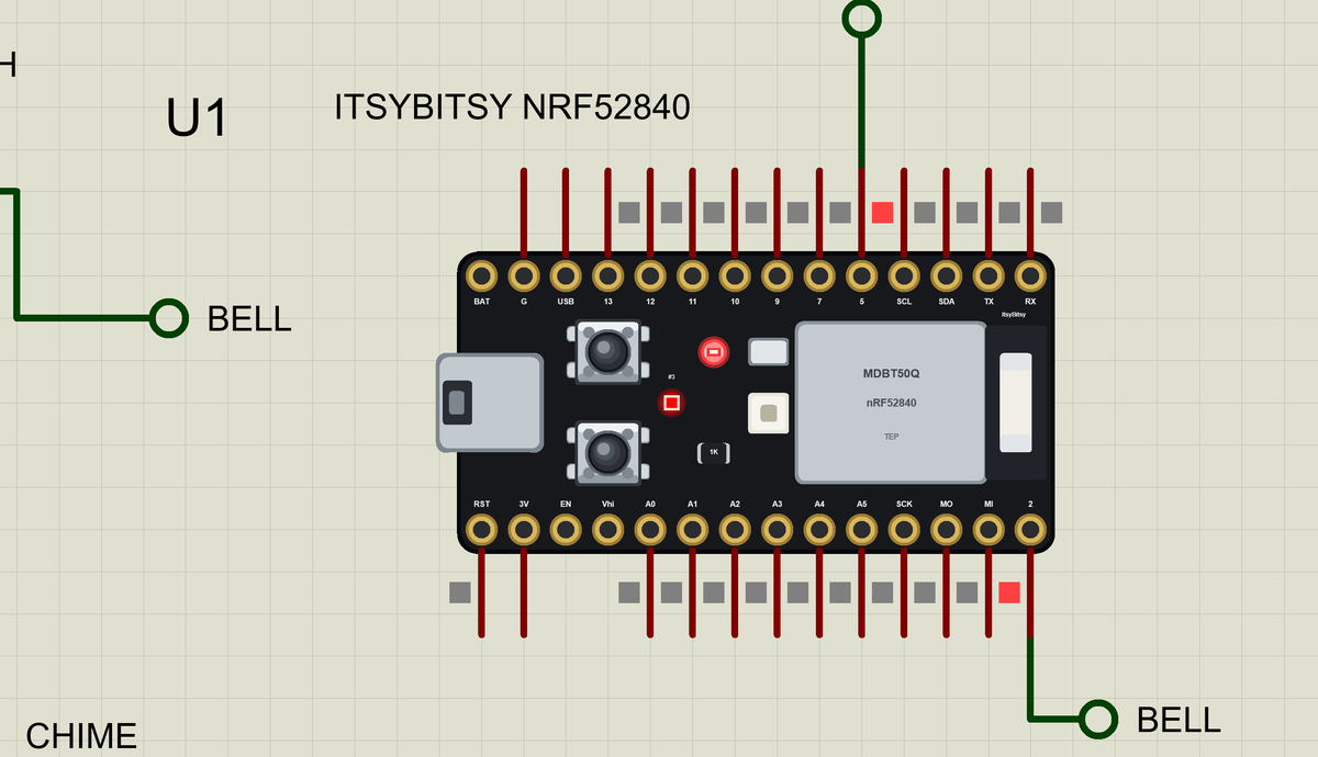
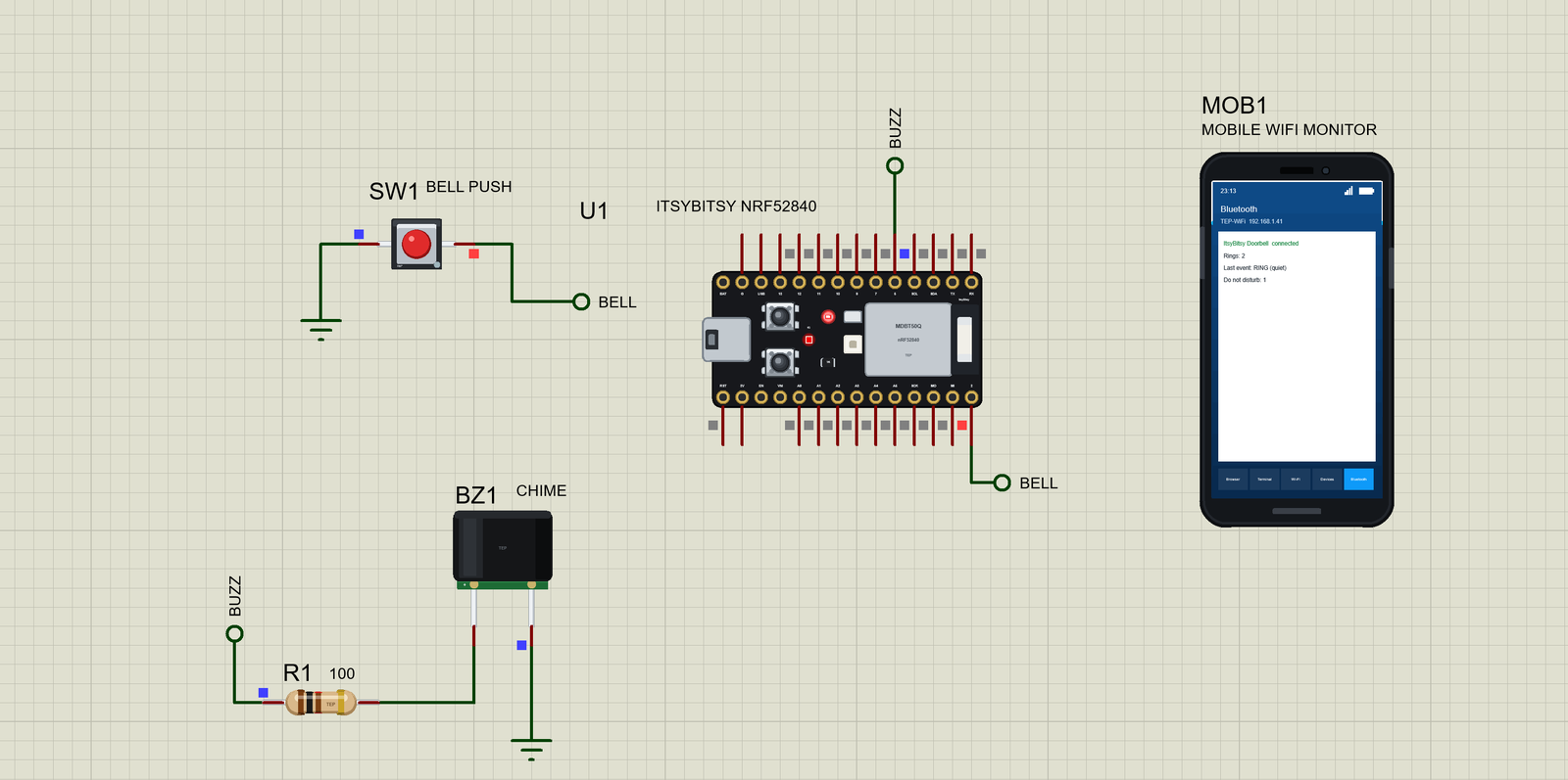
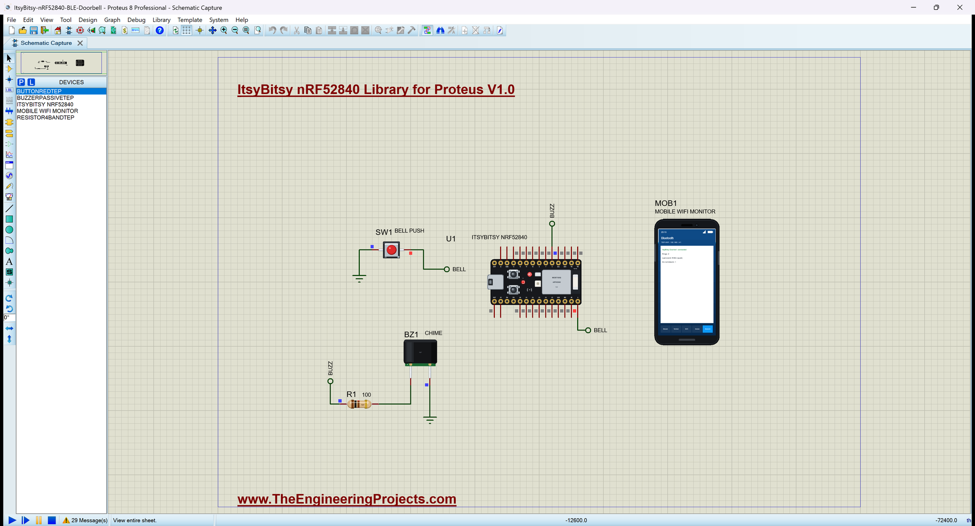
Open ItsyBitsy-nRF52840-BLE-Doorbell.pdsprj. U1 runs ItsyBitsy52_BLE_Doorbell.hex; SW1 is a red 6 mm push button from our Push Button Library for Proteus - pin 1 to ground, pin 2 on D2; BZ1 is our Passive Buzzer Library for Proteus through R1 (100 ohm) on D5; MOB1 is the phone.
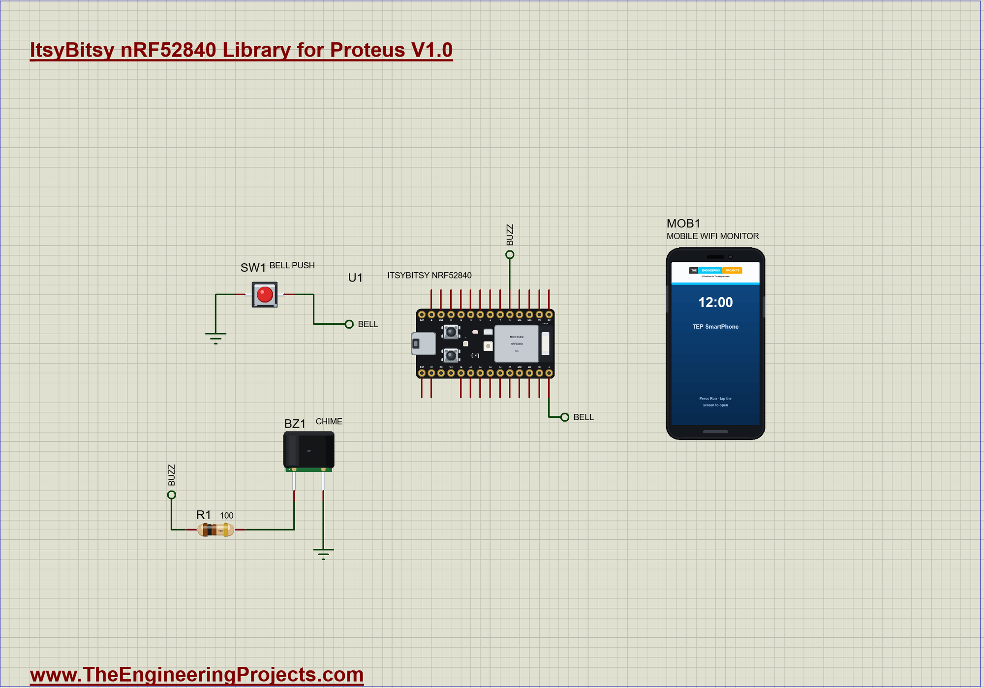
| What | Meaning |
|---|---|
| SW1 pressed | a ring: counted, sent to the phone |
| the chime | E5 then C5: "ding-dong" (not with do not disturb) |
| the red LED | lit for 2 s after each ring |
| the SWITCH | do not disturb on / off |
| pressed again within 2 s | the same visitor: not counted |
The Bluetooth Service
Three characteristics carry the number of rings, the last event and the do-not-disturb flag, each with a readable 0x2901 name for the phone:
BLEService bellService("19B100C0-E8F2-537E-4F6C-D104768A1214");
BLEIntCharacteristic ringsChar("19B100C1-E8F2-537E-4F6C-D104768A1214", BLERead | BLENotify);
BLEStringCharacteristic eventChar("19B100C2-E8F2-537E-4F6C-D104768A1214", BLERead | BLENotify, 16);
BLEByteCharacteristic quietChar("19B100C3-E8F2-537E-4F6C-D104768A1214", BLERead | BLENotify);
BLEDescriptor ringsLabel("2901", "Rings");
BLEDescriptor eventLabel("2901", "Last event");
BLEDescriptor quietLabel("2901", "Do not disturb");
Reading the Bell Push
A push button bounces when its contacts close. readBell() accepts a new level only after it stayed the same for 30 ms and calls ring() on the press:
void readBell() {                                           // the push bounces: a new level counts after 30 ms without a change
  const bool raw = digitalRead(BELL);
  if (raw != lastRaw) { lastRaw = raw; rawSince = millis(); }
  if (raw != level && millis() - rawSince >= DEBOUNCE_MS) {
    level = raw;
    if (level == LOW) ring();                               // pressed
  }
}
One Ring
ring() ignores a second press within 2 s, counts the visitor, lights the LED, tells the phone and starts the chime - unless do not disturb is on:
void ring() {                                               // one ring: count it, tell the phone, chime unless quiet
  if (lastRing && millis() - lastRing < GAP_MS) return;     // (pressed again within 2 s: the same visitor)
  lastRing = millis();
  rings++;
  ringsChar.writeValue(rings);
  digitalWrite(LED_BUILTIN, HIGH); ledUntil = millis() + LED_MS;
  if (quiet) {
    eventChar.writeValue("RING (quiet)");
    Serial.print(F(">> RING ")); Serial.print(rings); Serial.println(F(" (do not disturb: the phone only)"));
  } else {
    eventChar.writeValue("RING");
    tone(BUZZ, DING_HZ, DING_MS);                           // "ding" now, "dong" 0.4 s later from the loop
    dongDue = true; dongAt = millis() + DONG_AT_MS;
    Serial.print(F(">> RING ")); Serial.print(rings); Serial.println(F(" (ding-dong)"));
  }
}
Ding-Dong without Waiting
tone() with a duration plays a note in the background. The "ding" starts in ring(); 0.4 s later the loop starts the "dong", so the sketch never stops to wait:
if (dongDue && millis() >= dongAt) { dongDue = false; tone(BUZZ, DONG_HZ, DONG_MS); }Do Not Disturb
The board's SWITCH turns the chime off and on; the phone still gets every ring:
void readSwitch() {                                         // the SWITCH: do not disturb on / off
  const bool now = digitalRead(PIN_BUTTON1);
  if (now == lastSwitch) return;
  lastSwitch = now;
  if (now != LOW) return;
  quiet = !quiet;
  quietChar.writeValue(quiet ? 1 : 0);
  eventChar.writeValue(quiet ? "QUIET ON" : "QUIET OFF");
  Serial.println(quiet ? F(">> SWITCH: do not disturb ON") : F(">> SWITCH: do not disturb OFF"));
}
Run the Simulation
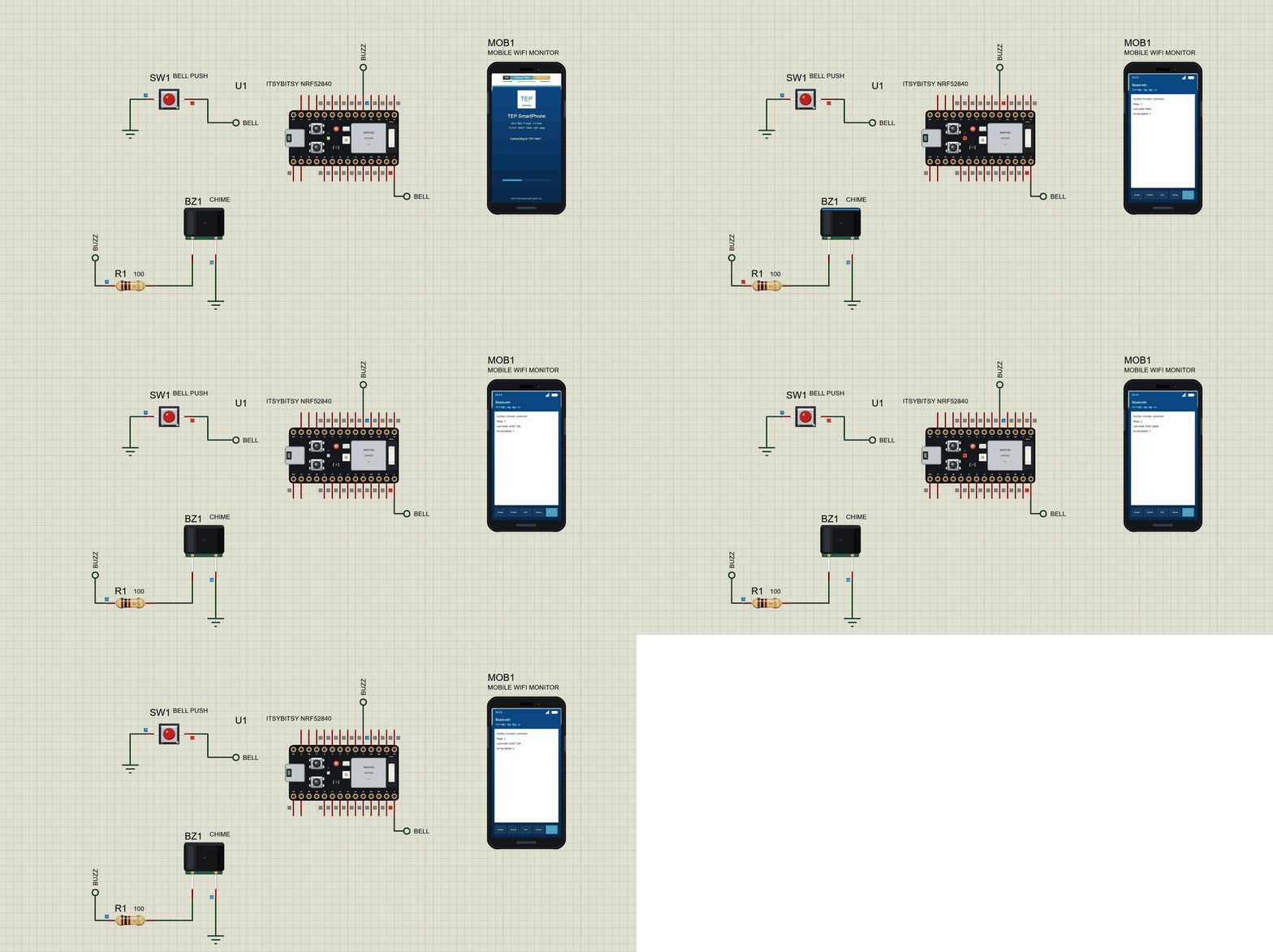
Press Run. The serial monitor - the same window as our TEP Serial Monitor Advance for Proteus - shows the name the board advertises:
ItsyBitsy nRF52840 Bluetooth Doorbell - The Engineering Projects
Advertising as "ItsyBitsy Doorbell"   the bell push on D2, SWITCH = do not disturb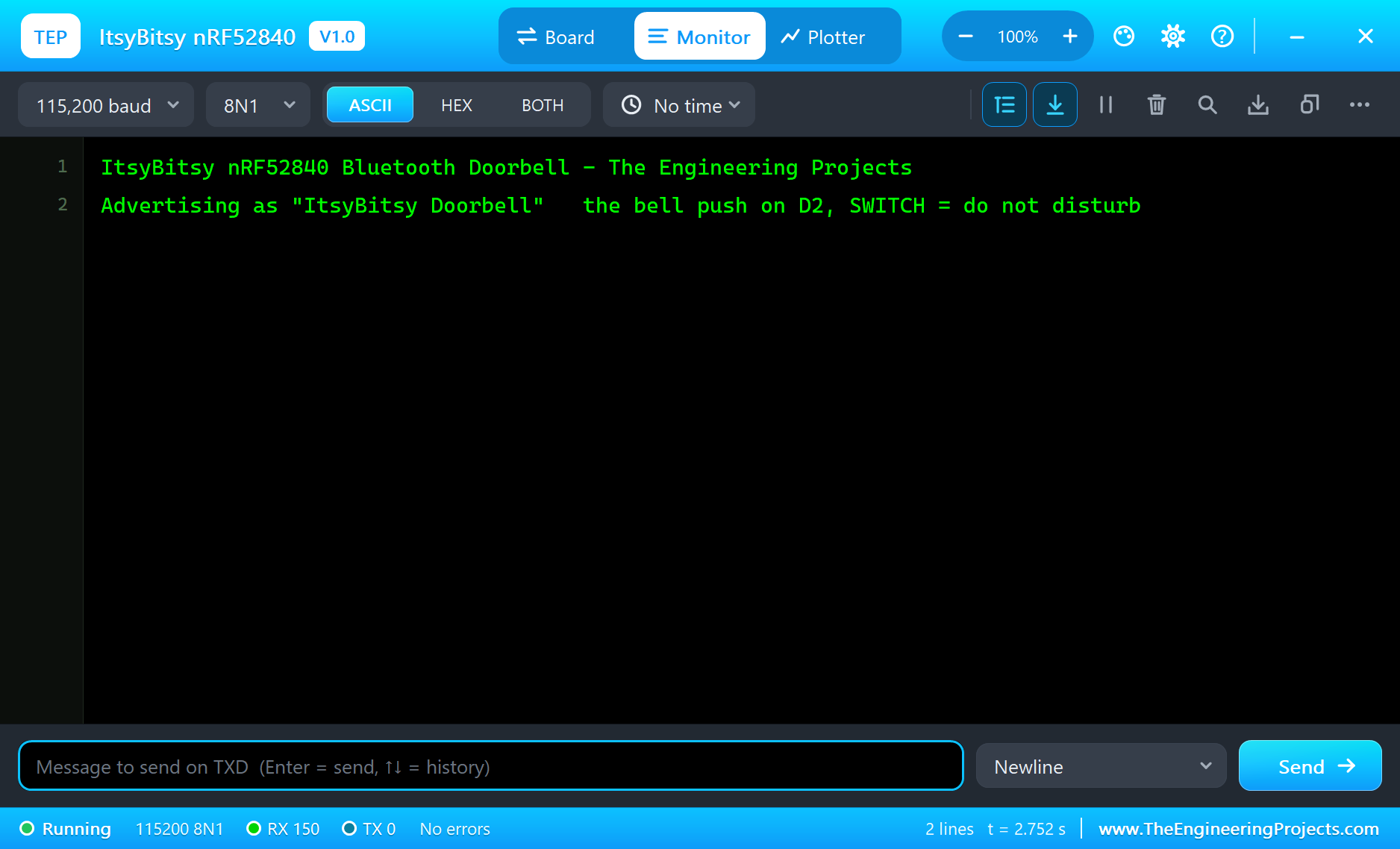
Connect the Phone
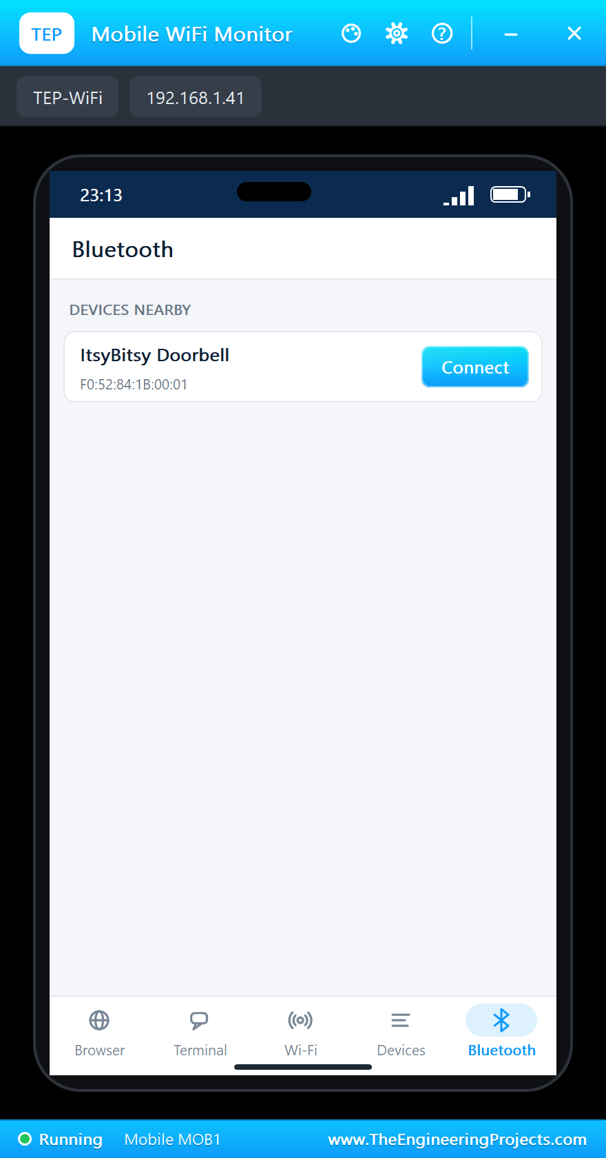
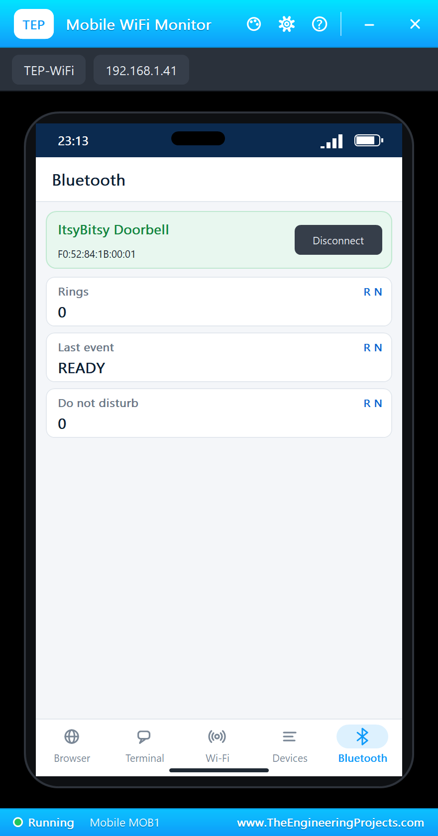
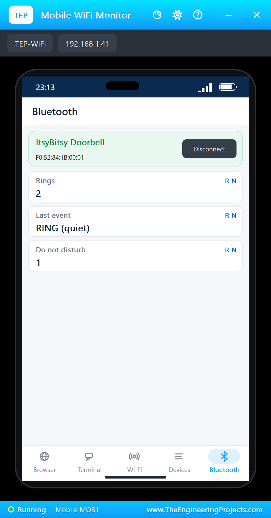
On the phone open the Bluetooth app, press SCAN and connect to "ItsyBitsy Doorbell":
A Visitor
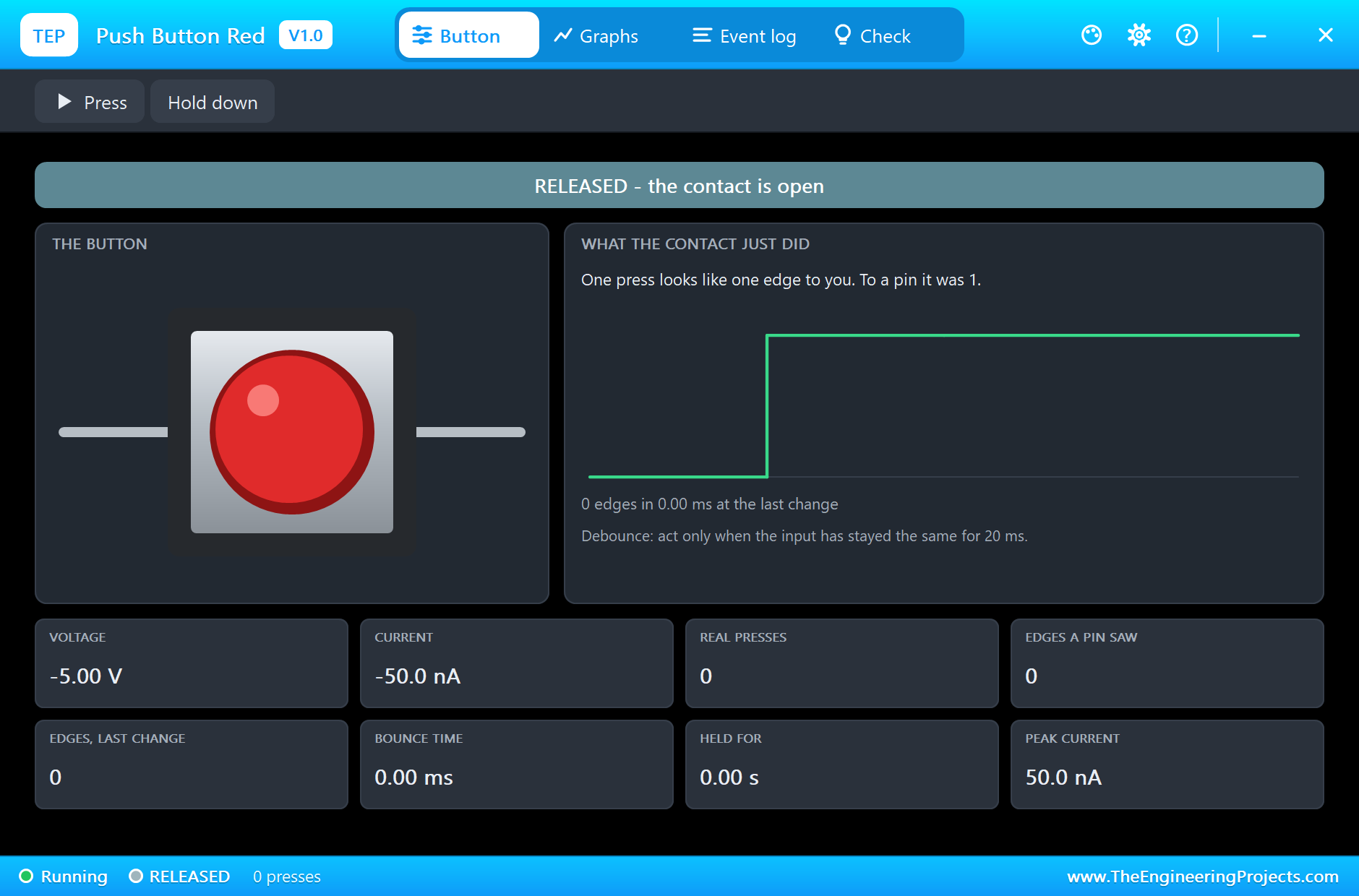
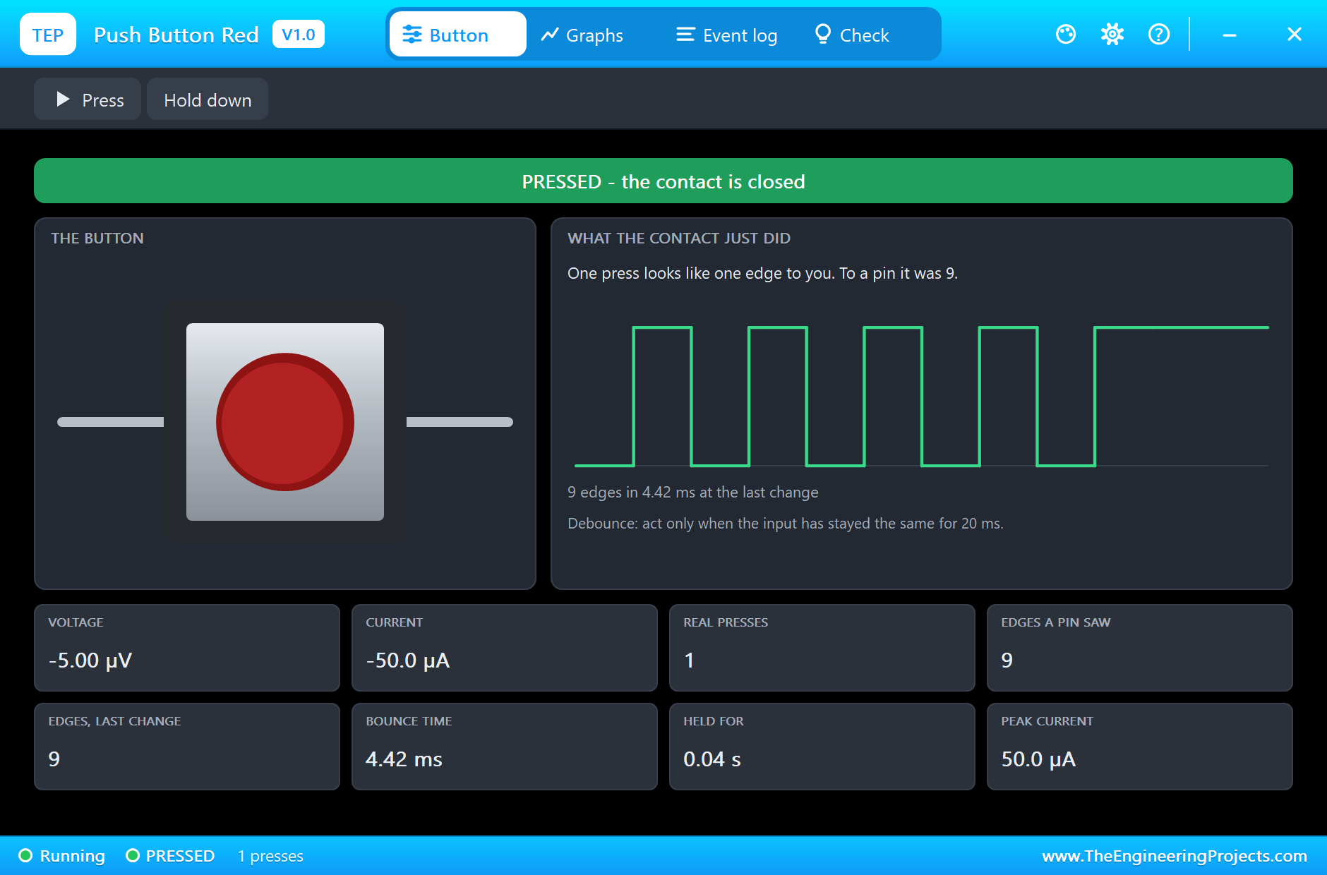
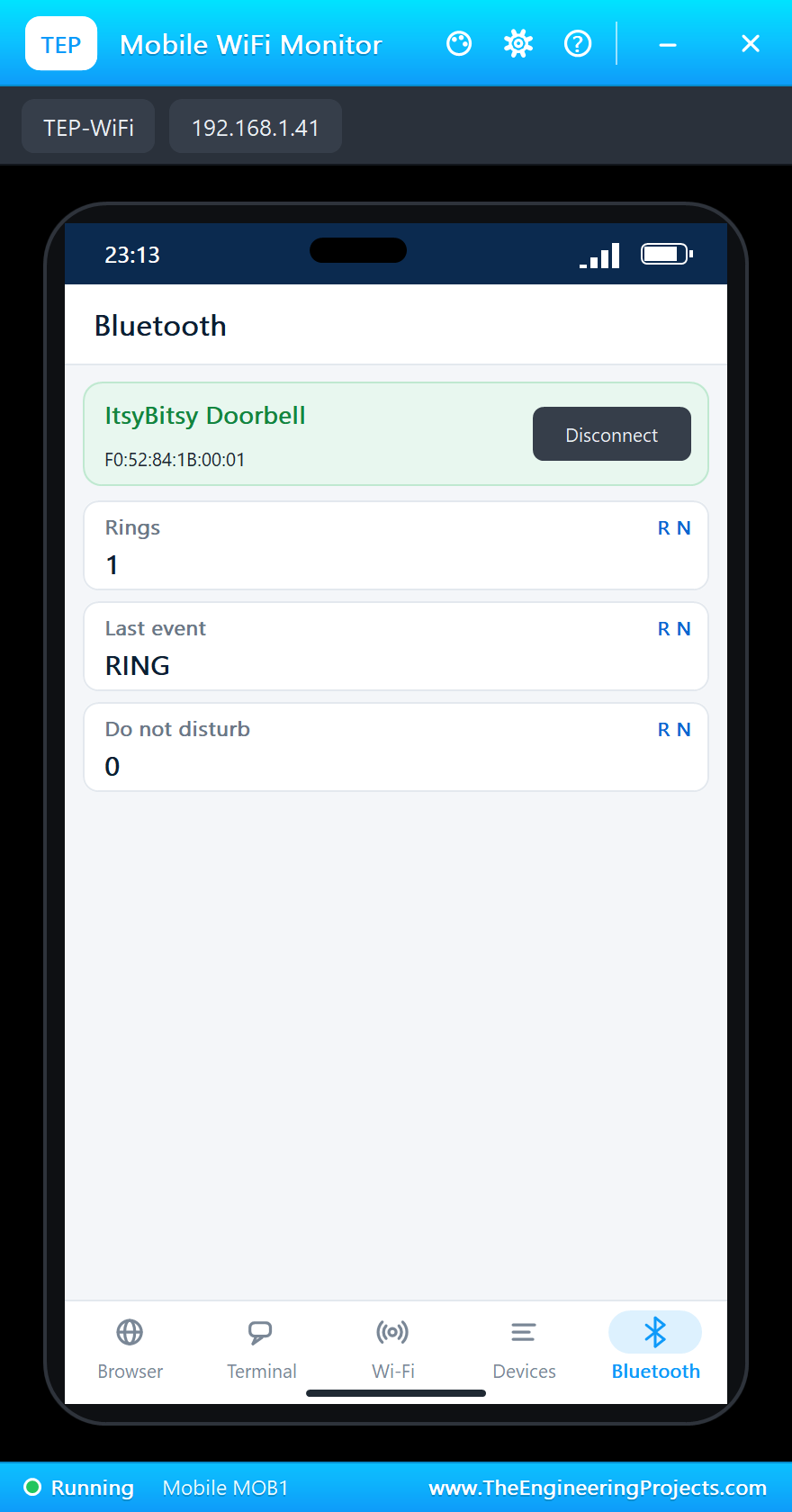
In the button's window click Press: RING 1, the chime plays "ding-dong" and the red LED lights. Here is the complete circuit while the simulation runs:
Do Not Disturb
Click the board's SWITCH: do not disturb is on. The next visitor rings without a chime - the phone still counts it. The SWITCH again turns the chime back on:
Phone connected
>> RING 1 (ding-dong)
>> SWITCH: do not disturb ON
>> RING 2 (do not disturb: the phone only)
>> SWITCH: do not disturb OFF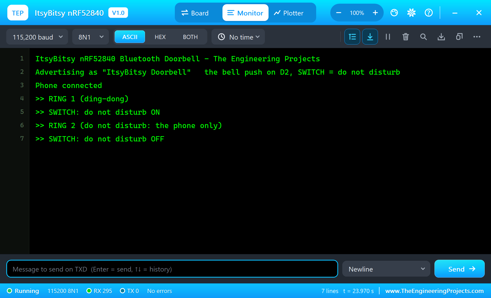
How a Passive Buzzer Chimes
A passive buzzer has no oscillator of its own: it sounds at whatever frequency the pin drives it. That is why it can play notes - E5 at 659 Hz and C5 at 523 Hz make the familiar falling "ding-dong". An active buzzer would only beep at its own fixed tone. The 100 ohm resistor limits the current from the pin.
Why Ignore a Second Press?
Visitors often press the bell twice or three times in a row. Counting each press would make one visitor look like three, and the chime would restart over and over. The sketch treats every press within 2 s of the last ring as the same visitor.
Pin 5: the 5 V Output
On the real ItsyBitsy, pin 5 goes through a small buffer chip powered from Vhi, so it drives a full 5 V signal - handy for 5 V LED strips and some buzzers. The demo uses it for the chime. In the simulation pin 5 is an ordinary 3.3 V pin, which the passive buzzer does not mind.
Battery Life
A doorbell waits almost all the time. On real hardware the nRF52840 can sleep and wake on the button's interrupt, and Bluetooth LE advertising every second or so costs very little - a coin cell or a small Li-Po can last months. The DotStar and the red LED are the big consumers, so a real bell lights them only briefly.
Debouncing in Detail
When the metal contacts of a push button meet, they bounce apart and together again a few times before they settle - usually for one to ten milliseconds. A fast microcontroller sees every one of those bounces as a separate press. The sketch solves it in software: it remembers when the level last changed and accepts a new level only after it has stayed the same for 30 ms. That is long enough to cover the bounce of a typical bell push and still far too short for a person to notice any delay.
Notifications instead of Polling
A phone could read the ring counter again and again to see whether it changed, but that wastes radio time and battery on both sides. With a notification the phone subscribes once - it writes to the characteristic's Client Characteristic Configuration descriptor, 0x2902 - and from then on the board sends the new value only when it changes. ArduinoBLE adds that descriptor by itself when a characteristic has the BLENotify property, so writeValue() is all the sketch needs.
The 0x2901 Descriptor
Bluetooth identifies characteristics by UUIDs, which mean nothing to a person. The Characteristic User Description descriptor, 0x2901, adds a readable name such as "Rings" or "Last event". Apps that understand it show the name next to the value, so you can tell the three values apart without a list of UUIDs.
Advertising and Connecting
Until a phone connects, the board advertises: it sends a short packet with its name and its service several times a second on the three advertising channels. A legacy advertising packet holds at most 31 bytes, which is why device names are kept short. When the phone connects, the advertising stops and the two devices exchange data on the data channels at the connection interval they agree on. After a disconnect the sketch simply advertises again.
Wiring a Real Bell Push
A door bell push is just a normally open momentary switch, so it connects exactly like SW1: one wire to the input pin, one to ground, with the internal pull-up keeping the pin HIGH while nobody presses. A long cable to the front door picks up noise, so on a real installation a 100 nF capacitor across the switch and the software debounce work well together. Keep the cable away from mains wiring.
Pull-Ups: Why the Pin Reads LOW When Pressed
Both inputs use INPUT_PULLUP: a resistor inside the chip connects the pin to 3.3 V, so it reads HIGH while the button is open. Pressing the button connects the pin to ground and it reads LOW. That is why the bell push needs only two wires and no external resistor, and why the sketch looks for LOW as the press. The board's SWITCH works the same way, and if a wire to the door breaks, the input simply stays HIGH - no false rings. A pull-down would do the opposite and needs the button wired to 3.3 V instead.
Why a Phone at All?
A chime only helps when somebody is in the house to hear it. The phone keeps a count of the rings and the last event, so you can see that a visitor came while you were in the garden or had headphones on - and do not disturb lets a sleeping baby or a night shift worker rest while the phone still collects every ring.
Try It Yourself
- Play a different tune for a second bell push on another pin (the back door).
- Blink the LED while do not disturb is on.
- Add a writable characteristic so the phone can switch do not disturb.
- Count the rings per hour and reset the count at midnight.
Ideas to Extend the Doorbell
- Add a PIR sensor to notice somebody at the door before they ring.
- Light a 5 V LED strip from pin 5 as a visual bell.
- Send the time of each ring to the phone.
- Use the DotStar to show the do-not-disturb state in colour.
Your Own Sketches
Write the sketch in the Arduino IDE with the board Adafruit ItsyBitsy nRF52840 Express (TEP Proteus), use Sketch > Export Compiled Binary and set the part's PROGRAM property to the .hex.
Moving to a Real ItsyBitsy nRF52840
- Install Adafruit's nRF52 board package in the Arduino IDE and select the ItsyBitsy nRF52840 Express.
- Port the Bluetooth part to Adafruit's Bluefruit library (or keep the same services with your own code).
- Wire the bell push from D2 to GND and the buzzer through 100 ohm to pin 5.
- Use pinMode(PIN_BUTTON1, INPUT_PULLUP) for the SWITCH and LED_BUILTIN for the red LED.
- Double-tap RESET to enter the bootloader if an upload fails.
The pins, the logic and the service stay the same; on the real board Adafruit's core takes the place of ours.
Properties of the ItsyBitsy nRF52840
| Property | What it does |
|---|---|
| PROGRAM | the sketch: a .hex from TEP Boards for Proteus (the ItsyBitsy nRF52840 board) |
| MONITOR, BAUD, AUTOOPEN | the built-in serial monitor: on, its baud rate (115200), open at Run |
Troubleshooting
- The phone's list is empty: call
BLE.begin(), set a local name andBLE.advertise(); callBLE.poll()in the loop. - One press rings twice: debounce the push - accept a new level only after 30 ms without a change.
- The chime stops the sketch: use
tone()with a duration and start the second note from the loop. - The SWITCH does nothing: use
pinMode(PIN_BUTTON1, INPUT_PULLUP)and act when it reads LOW. - A number goes wrong above 32767: int is 16 bits in the simulation - use long.
Limitations of the Simulation
- The DotStar is drawn, not modelled; the 5 V buffer of pin 5, the battery input and the regulator enable are not modelled.
- One phone is the central; the board cannot be a central itself. The radio's range is not modelled.
- Your sketch gets 8 KB of RAM in the simulation, and int is 16 bits there.
- ItsyBitsy and Adafruit are names of Adafruit Industries, nRF52840 of Nordic Semiconductor ASA, MDBT50Q of Raytac and Arduino of Arduino; this library is not made or endorsed by them or by Labcenter.
- Tested in Proteus 8.5 in November 2026 (the demo as shipped, about 24 s of simulation). Proteus 7 is not supported.
So, that was all about the ItsyBitsy nRF52840 Library for Proteus. I hope it helps you try your small Bluetooth ideas in a simulation before the board is on your desk - the button, the chime and the phone, all on one sheet. If you have any questions, ask in the comments and I will help you out. Till the next tutorial, take care and have fun!

Comments
0