


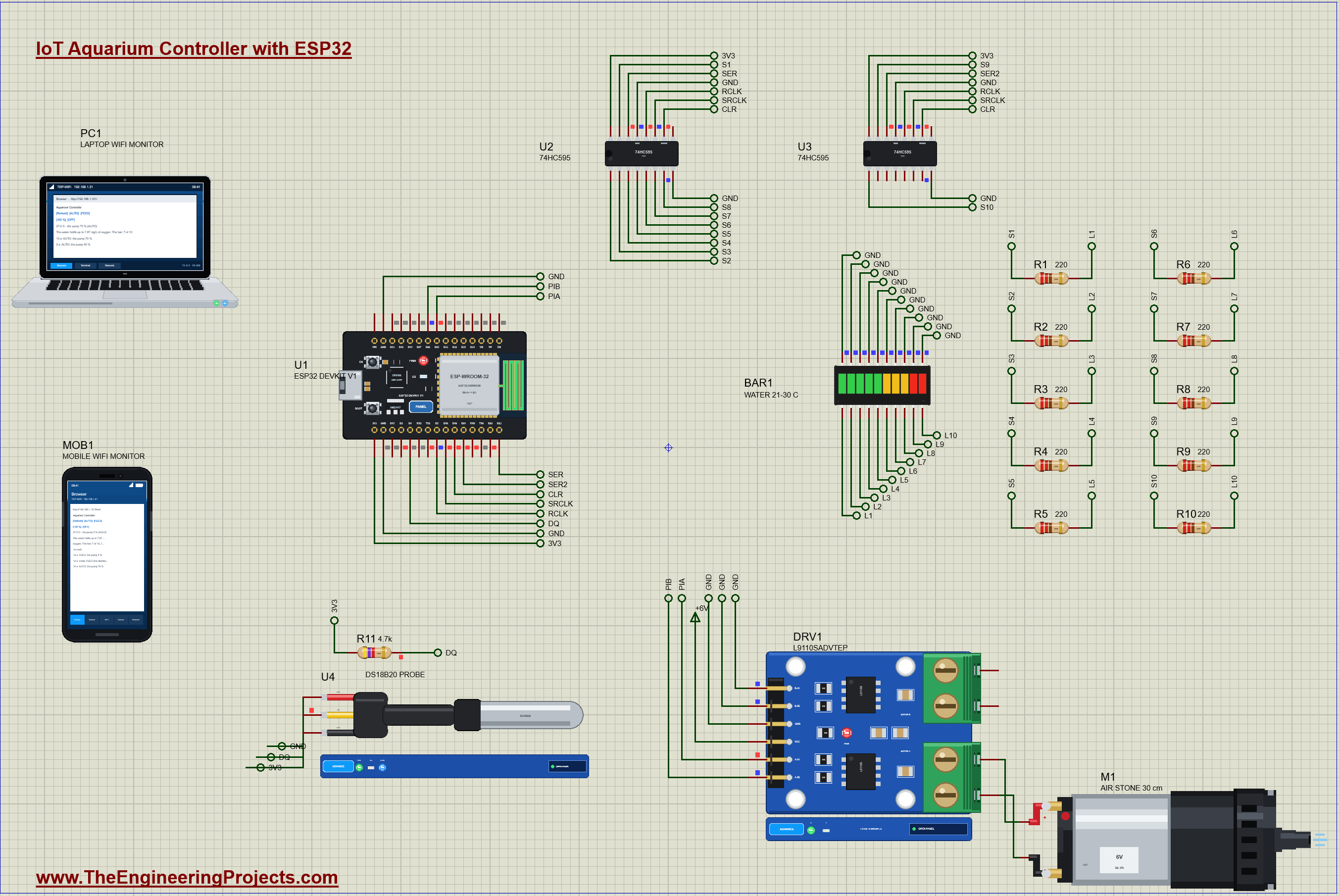
IoT Aquarium Controller with ESP32 - Proteus Simulation


Hello friends, I hope you all are doing great. Today, I am going to share the IoT Aquarium Controller with ESP32 - Proteus Simulation, the thirty-third project of our IoT Projects series. If you have searched for a Proteus simulation of an ESP32 aquarium controller with a 74HC595 shift register and an LED bar graph, here is a complete one. An ESP32 DevKit V1 measures the water's temperature with a DS18B20 waterproof probe, shows it on a 10-segment LED bar graph driven by two 74HC595 shift registers, runs the tank's air pump harder as the water warms, stops the pump while the fish are fed, warns when the water gets too warm, and serves a live web dashboard that you can open on a laptop or a phone.
Fish breathe the oxygen dissolved in the water, and warm water holds less of it: that is why an aquarium needs more air on a hot day. In this tutorial, we will go through the circuit, learn how a 74HC595 turns three pins into eight outputs and how two of them share a clock to give sixteen, light an LED bar graph safely, read a DS18B20 on OneWire, see how much oxygen water can hold at each temperature, drive a 6 V air pump through an L9110S with PWM, walk through the Arduino sketch, and then run the simulation: the water warming from 24 to 31 degrees, the pump speeding up, a feeding pause, a too-warm alarm and the water cooling again. At the end, you can download the project with the sketch and every library file.
NOTICE: Our team has put a lot of effort into this project: the circuit, the code and every part in the simulation are our own work, and you get them all free. Your feedback is the fuel that keeps us going, so please tell us what you think in the comments below. And if our free projects help you, you can buy us a coffee. So, let's get started with the IoT Aquarium Controller with ESP32 - Proteus Simulation:
What Does This Aquarium Controller Do?
- Measures the water: a DS18B20 waterproof probe on OneWire, one reading a second, to 1/16 of a degree.
- A bar-graph thermometer: ten segments, one at 21 degrees C and all ten at 30, green, yellow and red.
- Four pins, ten LEDs: two 74HC595 shift registers, a data line each, share one shift clock and one latch.
- Aerates by temperature: the air pump at 40 % at 24 degrees or below, rising to 100 % at 30.
- Feeding pause: FEED stops the pump for 15 seconds so the food sinks.
- Too-warm alarm: above 30 degrees the bar's top segment blinks and the dashboard warns.
- A dashboard: the water, the oxygen it can hold, the pump and AUTO, FEED, 100 % and OFF.
It is a great project for learning how shift registers multiply a microcontroller's outputs, how to read a OneWire sensor, and how to control a small DC pump with PWM. In the simulation, the DS18B20's pop-up sets the water's temperature, and the pump's pop-up shows the bubbles rising from the air stone.
Components Used in the Proteus Simulation
All the parts come from our Proteus libraries, each with its own tutorial. The project zip at the end includes every LIB and DLL file.
| Part | Proteus device | Library post | Connection |
|---|---|---|---|
| ESP32 DevKit V1 | ESP32 DEVKIT V1 | ESP32 DevKit V1 Library for Proteus | U1, TEP-WiFi 192.168.1.101 |
| DS18B20 waterproof probe | DS18B20PROBEADVTEP | DS18B20 Library for Proteus | U4, DQ D4, R11 4.7 k |
| 74HC595 shift register x 2 | SN74HC595TEP | 74HC595 Shift Register Library for Proteus | U2, U3: SER D23 / D21, SRCLK D18, RCLK D5 |
| 10-segment LED bar graph | LEDBAR10MIXTEP | LED Bar Graph Library for Proteus | BAR1, through R1 - R10 |
| Resistors 220 ohm and 4.7 kohm | RESISTOR4BANDTEP | Resistor Library | R1 - R10, R11 |
| L9110S motor driver | L9110SADVTEP | L9110S Motor Driver Library | DRV1, A-IA D25, A-IB D26 |
| 6 V mini air pump | MINIAIRPUMPTEP | Mini Air Pump Library for Proteus | M1, an air stone 30 cm deep |
| Laptop WiFi Monitor | LAPTOP WIFI MONITOR | Laptop WiFi Monitor | PC1 |
| Mobile WiFi Monitor | MOBILE WIFI MONITOR | Mobile WiFi Monitor | MOB1 |
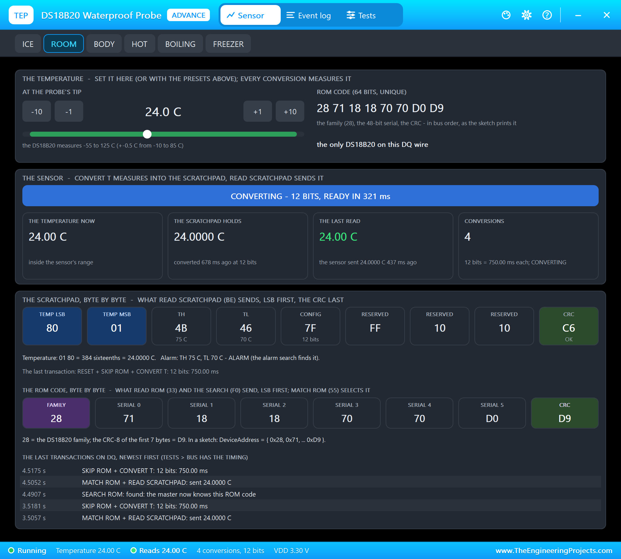
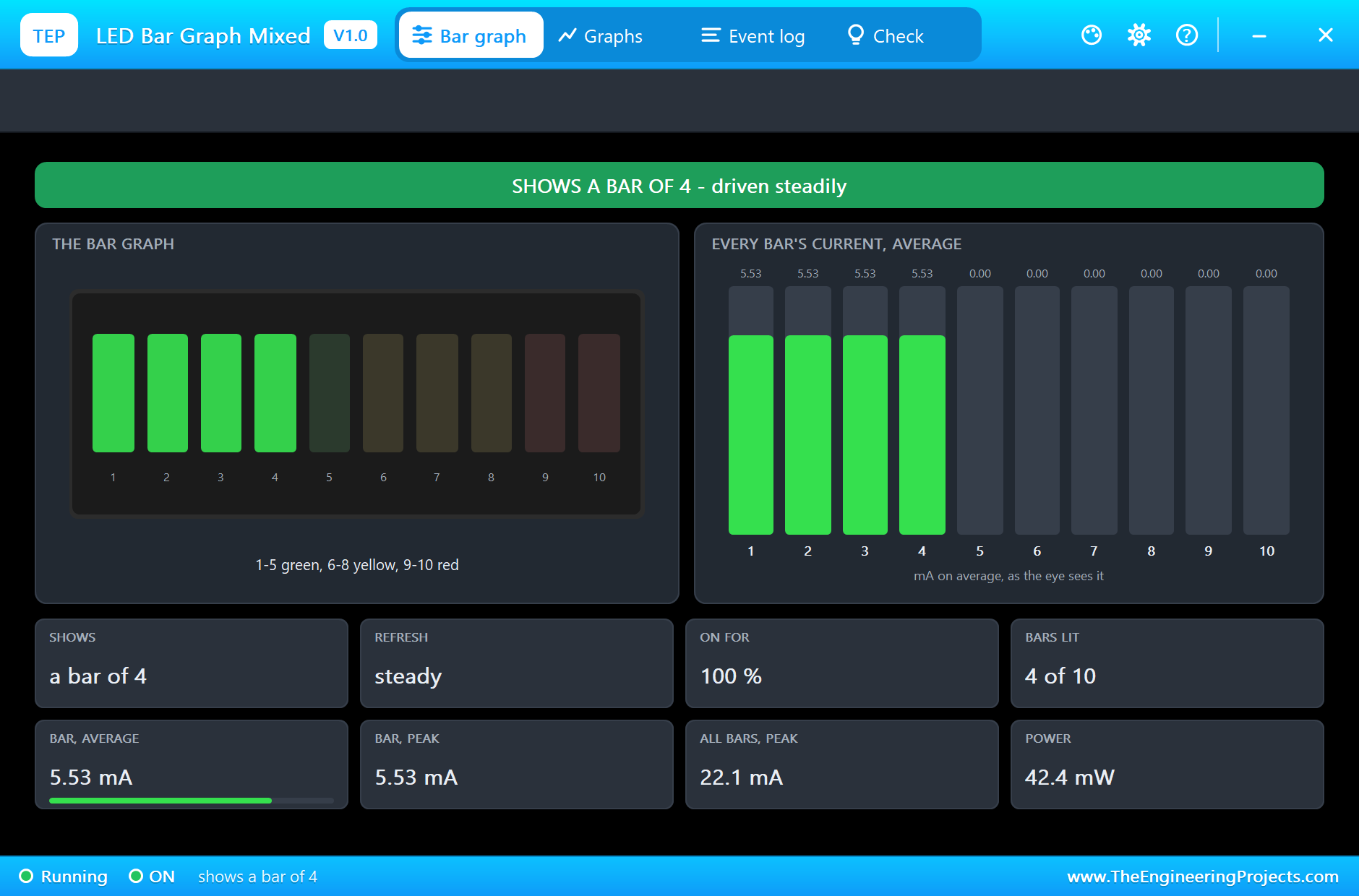
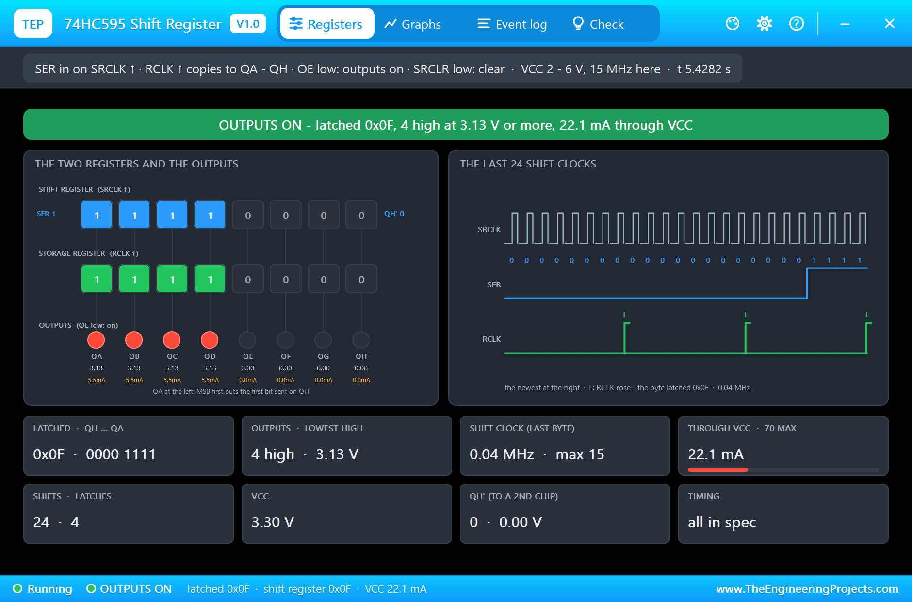
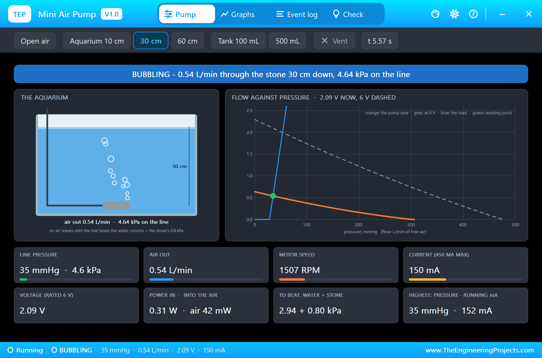
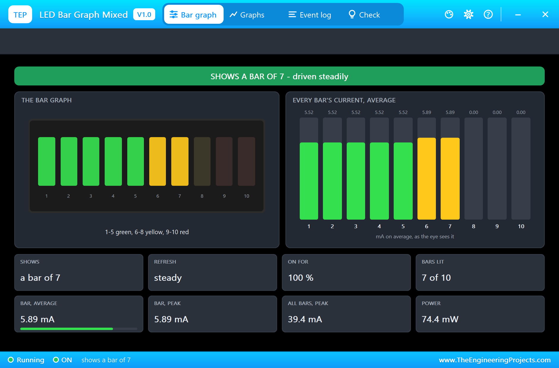
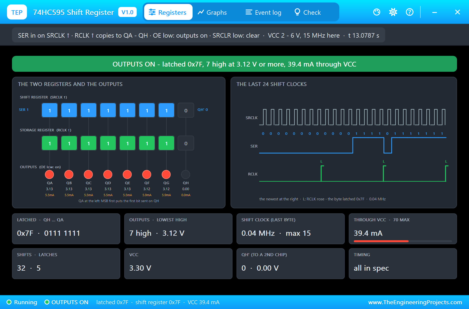
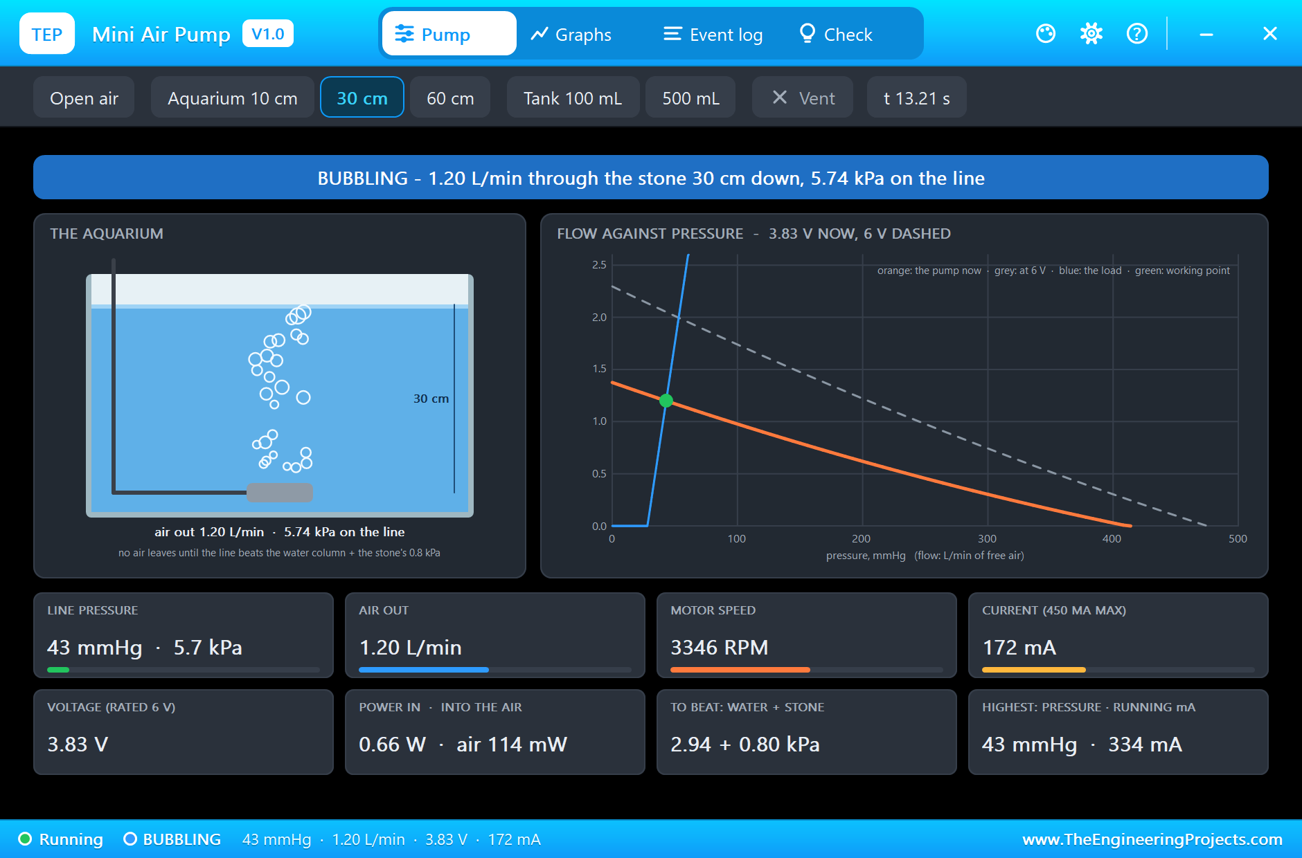
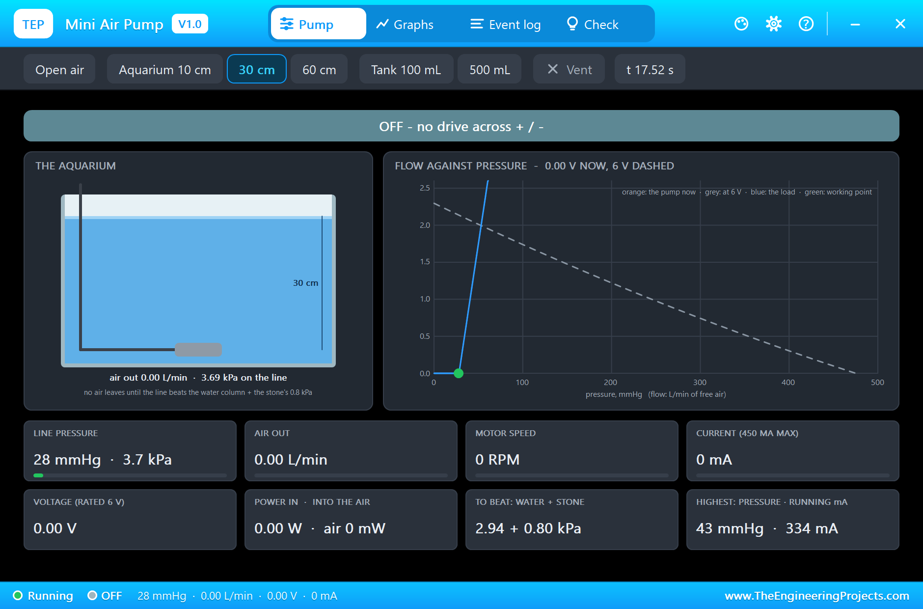
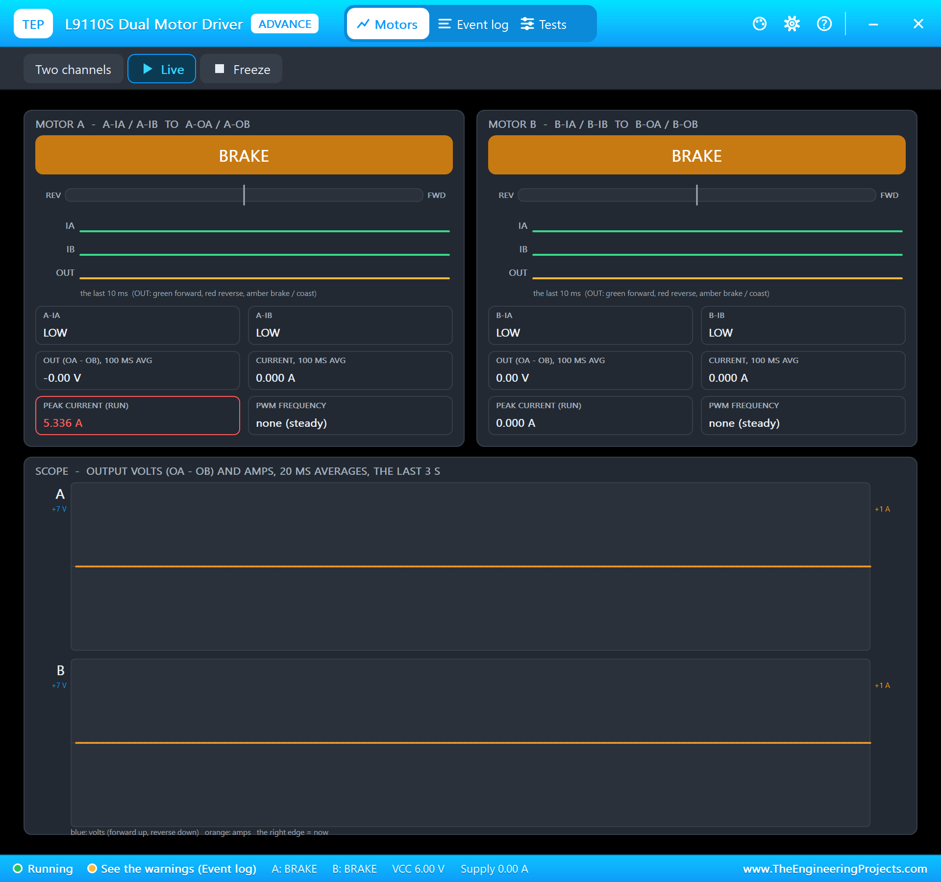
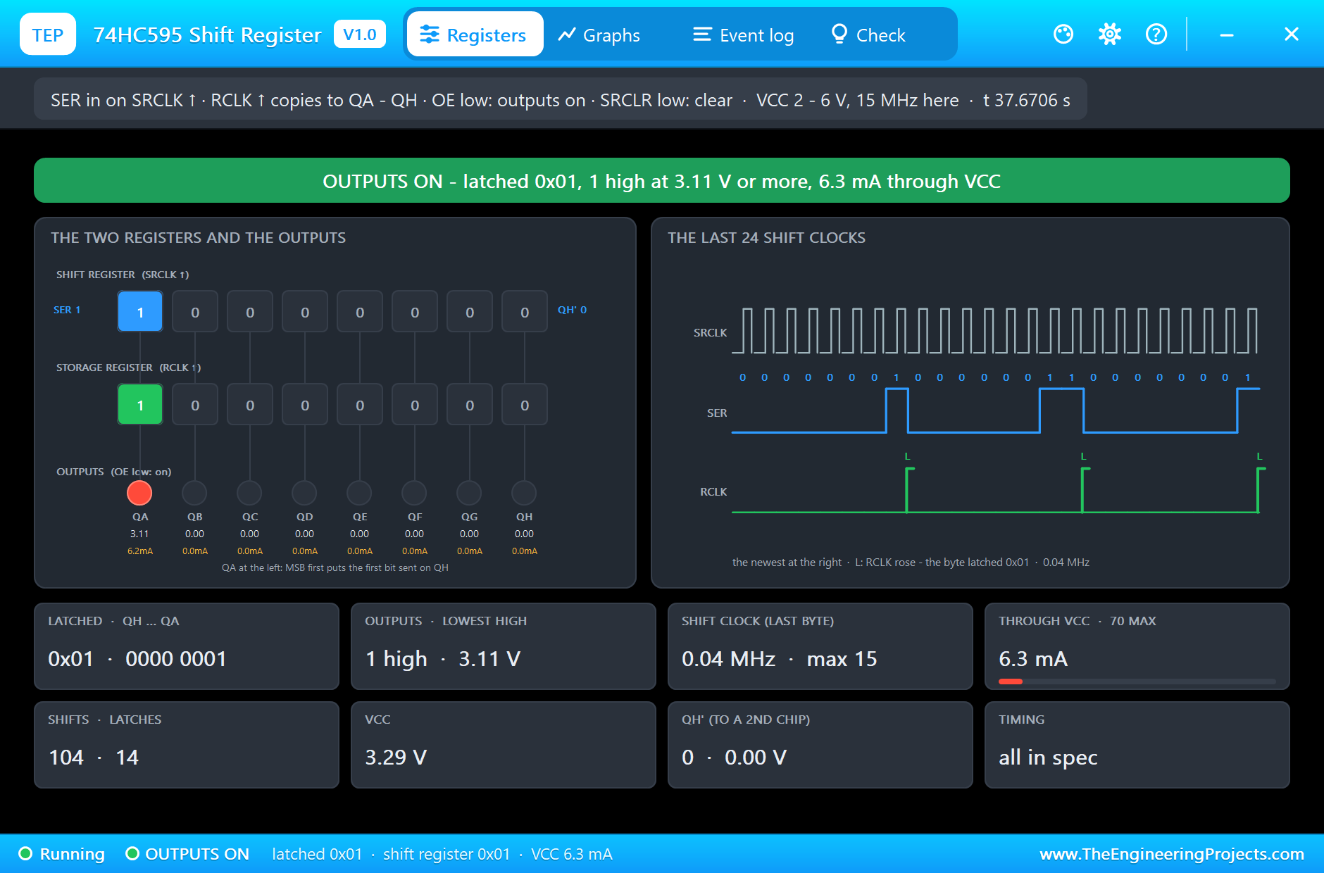
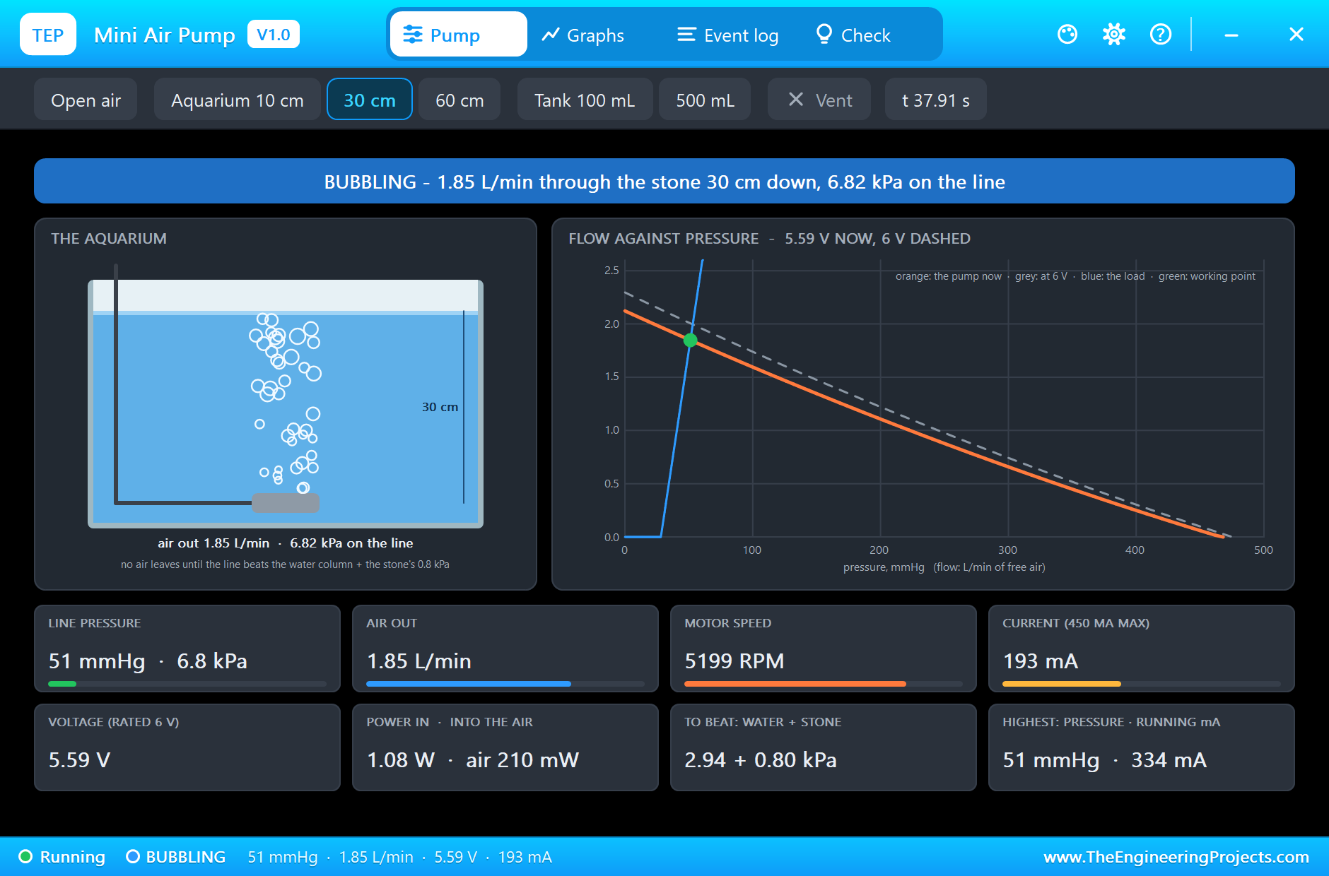
The probe, the shift registers, the bar, the driver and the pump are models with pop-ups. The DS18B20's pop-up sets the temperature and shows every OneWire transaction. The 74HC595's pop-up shows its shift register, its storage register and the eight outputs with their volts and milliamps. The bar's pop-up shows the ten segments and their currents. The pump's pop-up shows the bubbles, the speed, the flow and the pressure on the air line.
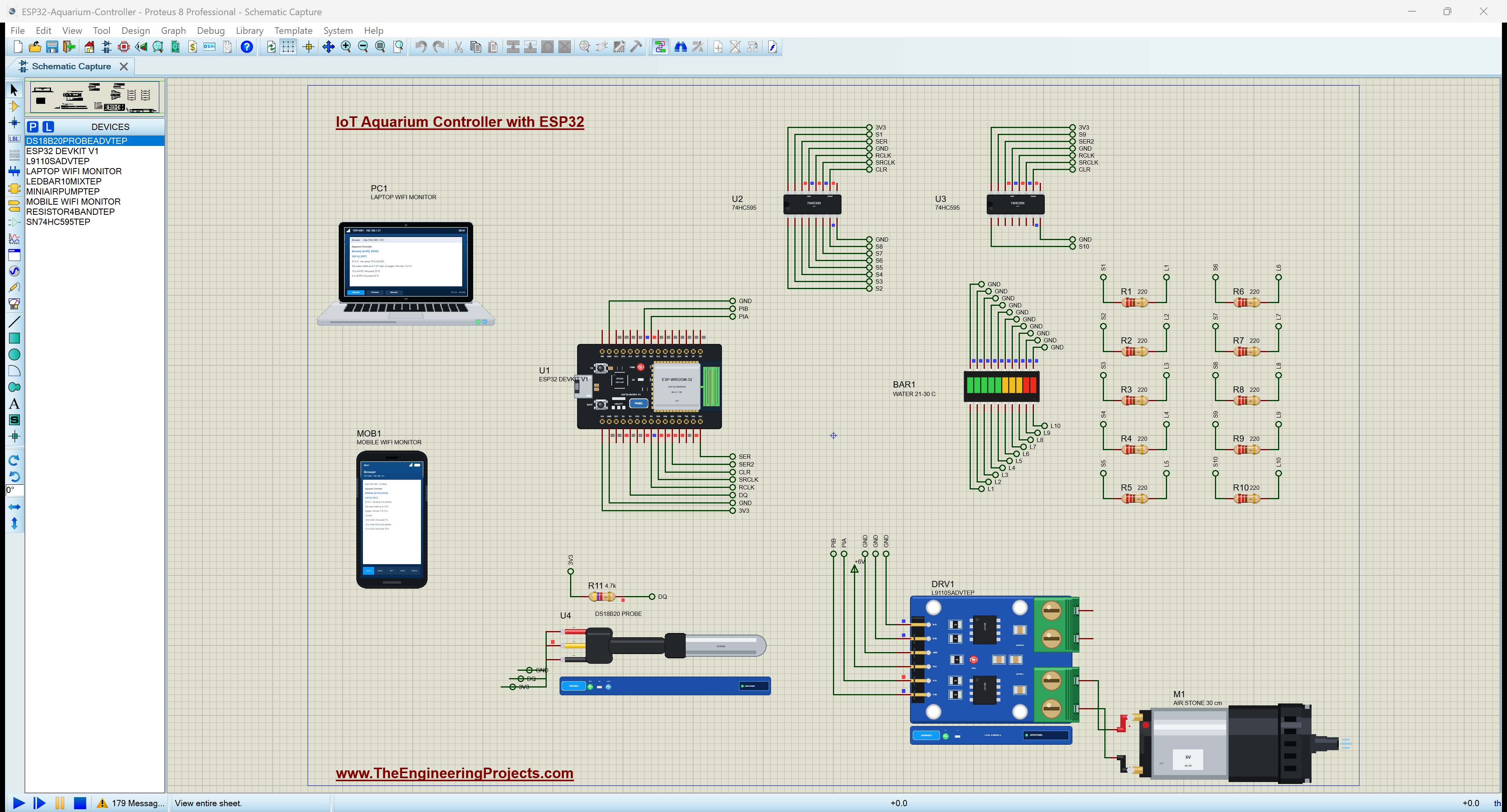
Proteus Simulation of the Aquarium Controller: the Circuit
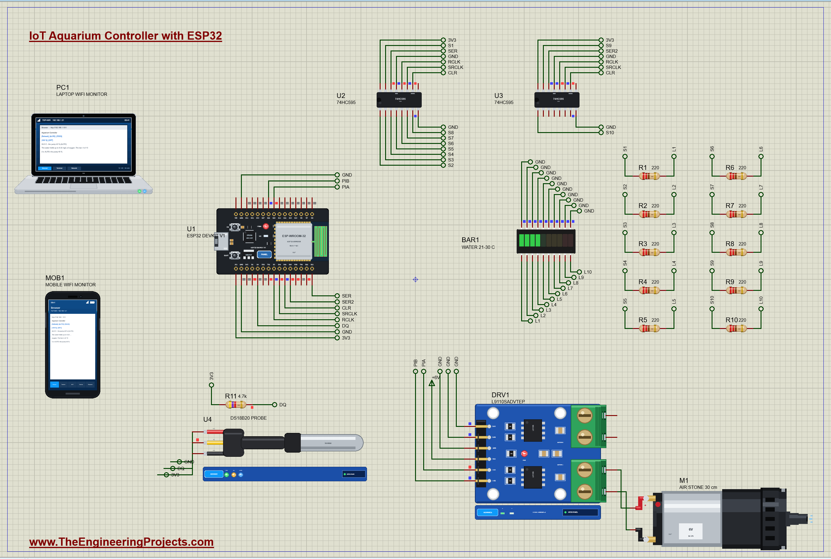
| Part | Pins | ESP32 DevKit V1 / other |
|---|---|---|
| U4 DS18B20 | VDD / DQ / GND | 3V3 / D4 (R11 4.7 k to 3V3) / GND |
| U2, U3 74HC595 | SER / SRCLK / RCLK / SRCLR / OE | D23 (U2), D21 (U3) / D18 / D5 / D19 / GND |
| U2, U3 74HC595 | VCC / GND / outputs | 3V3 / GND / U2 QA - QH and U3 QA - QB to R1 - R10 |
| BAR1 | A1 - A10 / K1 - K10 | R1 - R10 (220 ohm) / GND |
| DRV1 L9110S | A-IA / A-IB / VCC / B-IA, B-IB | D25 / D26 / +6V / GND |
| M1 air pump | + / - | the L9110S's A-OA / A-OB |
The ESP32 has plenty of pins, but every LED on its own pin soon uses them up. Two 74HC595 chips give sixteen outputs from four signals: a data line for each chip, one shared shift clock and one shared latch. SRCLR, the chips' clear input, comes from D19 so the sketch can hold it high; tied to the 3.3 V net in our first test it read low and kept the registers empty. The air pump runs on its own 6 V supply through the L9110S; the ESP32 only sends it a PWM signal.
How the Aquarium Controller Works
The 74HC595 Shift Register
A 74HC595 holds two 8-bit registers. The shift register takes one bit at a time: on each rising edge of SRCLK, every bit moves one place along and the level on SER enters at the start. The storage register holds what the outputs show: on a rising edge of RCLK, it copies the whole shift register at once. So the sketch can shift eight new bits in while the LEDs still show the old picture, and the new picture appears in one step, without flicker. OE low switches the outputs on; SRCLR low empties the shift register.
For more outputs there are two ways. The last bit of the shift register comes out on QH', and wired to a second chip's SER the two act as one 16-bit register that takes 16 clocks. Or each chip gets its own data line and both share the clock and the latch: then both fill in the same 8 clocks, for one more pin. This project uses the second way; in our simulation the bit chained from QH' did not register at 3.3 V, and the parallel way is faster anyway. Worked example: 27 degrees lights seven segments, the bit pattern 0000 0000 0111 1111. In each of the 8 clocks the sketch puts one bit of 0x7F on U2's data line and one bit of 0x00 on U3's, and one pulse on RCLK then lights segments 1 to 7.
Lighting an LED Bar Graph
Each segment of the bar is an LED: its anode on a 74HC595 output through a 220 ohm resistor, its cathode on ground. At 3.3 V, a red LED drops about 2 V, so the resistor sets about (3.3 - 2) / 220 = 6 mA, enough for a clear light. Without resistors, the outputs would try to push far more current than a 74HC595 can give: 35 mA a pin and 70 mA for the whole chip at most.
Warm Water Holds Less Oxygen
The oxygen that water can hold when it is saturated falls as it warms. A standard formula for fresh water at sea level is DO = 14.652 - 0.41022 T + 0.007991 T² - 0.000077774 T³ milligrams per litre, with T in degrees C. Worked example: at 24 degrees, 8.33 mg/L; at 30 degrees, only 7.44 mg/L, 11 % less, while the fish, being warmer, need more. So the sketch runs the air pump at 40 % up to 24 degrees and raises it in a straight line to 100 % at 30: 70 % at 27 degrees.
The Air Pump and the Air Stone
The pump is a 6 V diaphragm pump: a small motor works a rubber diaphragm between two one-way valves. Its air goes down a tube to an air stone 30 cm under water, and nothing bubbles out until the pressure in the line beats the water column, about 3 kPa for 30 cm, plus the stone's own resistance. Above that, the faster the motor turns, the more air. The L9110S switches the 6 V on and off at the PWM frequency, so the motor sees the average voltage: about 40 % of the supply at 40 % duty.
The DS18B20 on OneWire
The DS18B20 talks on one data wire plus ground, its DQ pulled up to 3.3 V by 4.7 k. The ESP32 sends CONVERT T, the chip measures for 750 ms at 12 bits, and then READ SCRATCHPAD returns the temperature in 1/16 of a degree. The sketch never waits: it starts a conversion, comes back a second later, reads the result and starts the next one.
The Arduino Code Explained
The whole sketch is included in the download. It uses OneWire and DallasTemperature for the probe, the ESP32's WiFi and WebServer libraries for the dashboard, and drives the bar and the pump itself. At the top are the pins and the rules:
const byte PROBE_PIN = 4, SER = 23, SER2 = 21, SRCLK = 18, LATCH = 5;   // SER: U2 (segments 1 - 8), SER2: U3 (9 - 10)
const byte CLEAR = 19;                                    // the 74HC595s' SRCLR (low = clear): held high
const float T_LOW = 24.0, T_HIGH = 30.0; // AUTO: MIN_POWER at or below T_LOW, 100 % at T_HIGH
const byte MIN_POWER = 40; // % (the stone needs some pressure before any air bubbles out)The Bar Graph
shiftPair() sends two bytes at once, most significant bit first, one bit of each on its own data line before every rising edge of the shared clock:
    digitalWrite(SER, bitRead(a, i));
    digitalWrite(SER2, bitRead(b, i));
    digitalWrite(SRCLK, HIGH);                            // SRCLK rising: both chips take their bit
    digitalWrite(SRCLK, LOW);
showBar() turns a number of segments into a 16-bit pattern, sends its two halves and latches them:
uint16_t bits = n >= 10 ? 0x03FF : (1u << n) - 1; digitalWrite(LATCH, LOW);
shiftPair(bits & 0xFF, bits >> 8); // segments 1 - 8 to U2's QA - QH, 9 and 10 to U3's QA and QB
digitalWrite(LATCH, HIGH); // RCLK rising: both chips show their new byte at once byte n = isnan(waterC) ? 0 : constrain((int)floor(waterC - BAR_FIRST) + 1, 0, 10);The Oxygen and the Pump
return 14.652 - 0.41022 * t + 0.007991 * t * t - 0.000077774 * t * t * t; return MIN_POWER + (100 - MIN_POWER) * (t - T_LOW) / (T_HIGH - T_LOW); analogWrite(PUMP_IA, map(p, 0, 100, 0, 255)); // A-IB stays LOW: the motor turns one wayThe Probe, FEED and the Alarm
A fresh DS18B20 holds 85 degrees until its first conversion, so setup() waits for one; after that the sketch switches to the non-blocking way:
probe.setWaitForConversion(false); // from now on: start a conversion, read it a second later if (mode == FEED && now - feedAt >= FEED_MS) { mode = AUTO; event("feeding over: AUTO again"); update(); }
if (tooWarm && now - lastBlink >= 500) { lastBlink = now; blinkOn = !blinkOn; showBar(segments, blinkOn); }The pages are / (the dashboard), /auto, /feed, /full (100 %) and /off (the modes) and /data (JSON). The ESP32's WebServer keeps only a few routes, so / and /data are registered and the four modes go through onNotFound, which reads the address. The dashboard puts its links first and stays short, because the WiFi Monitors show one screen of a page.
How to Run the Proteus Simulation
- Download the project zip below and install the library files (the steps are under the download button).
- Open ESP32-Aquarium-Controller.pdsprj from the Proteus Simulation folder. Keep the HEX and the DLL files next to it.
- Press Play. The water is at 24 degrees: four segments, the pump at 40 %.
- In the DS18B20's pop-up (U4), press +1 or +10 to warm the water and watch the bar and the pump.
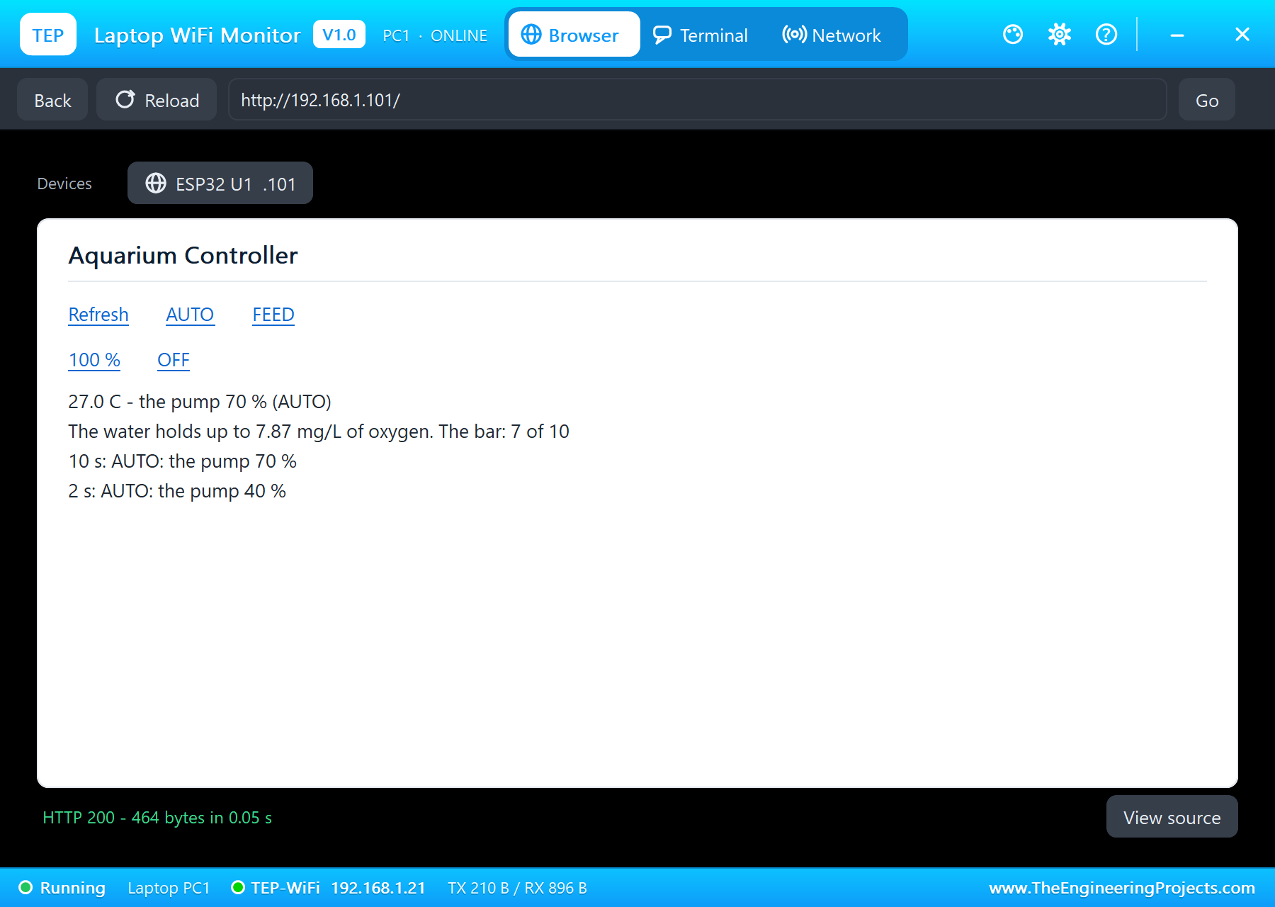
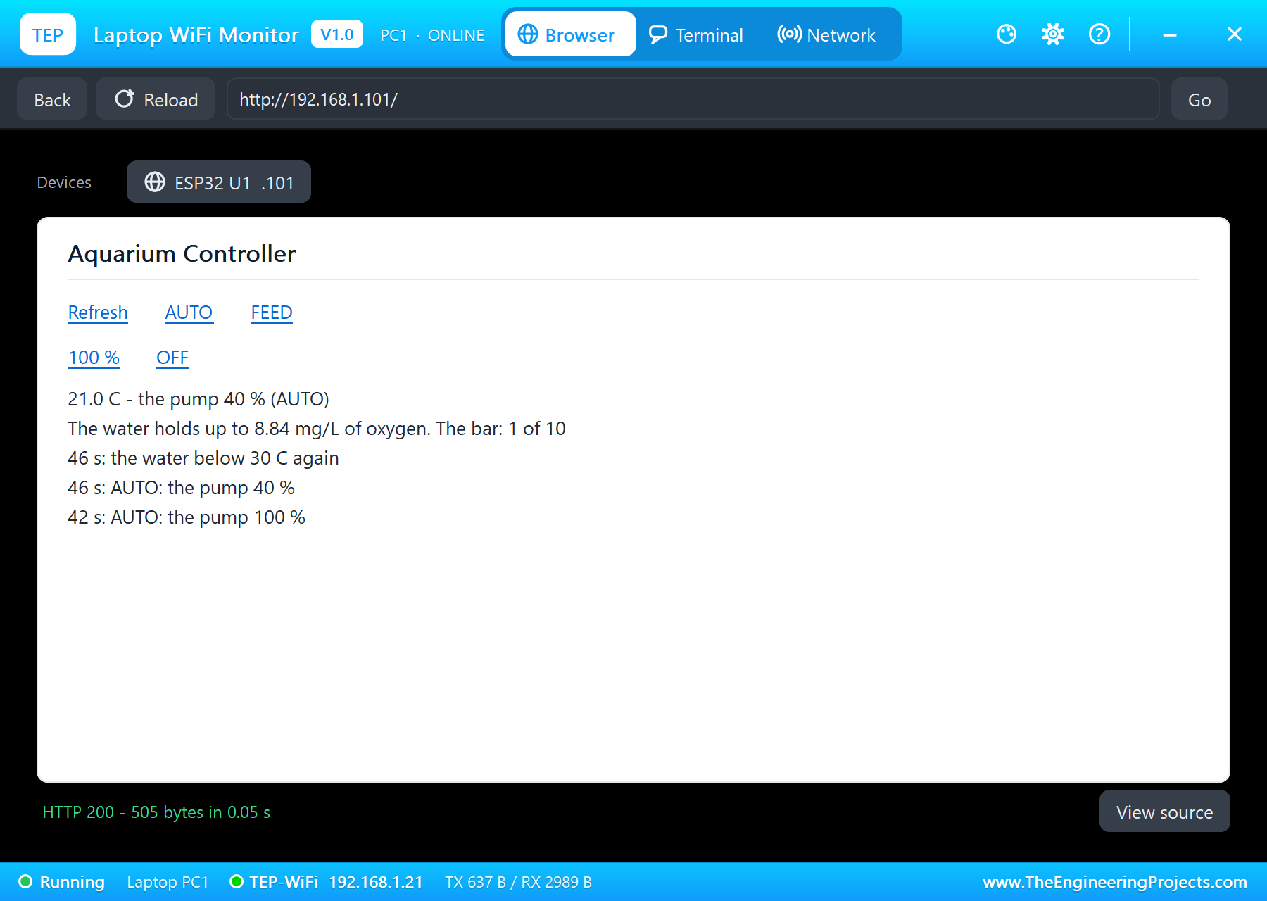
- Open the Laptop WiFi Monitor (PC1) or the Mobile WiFi Monitor (MOB1), press Go and try FEED, 100 %, OFF and AUTO.
Simulation Results: the Aquarium Controller in Proteus
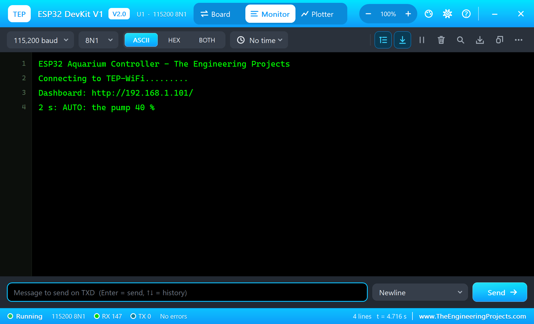
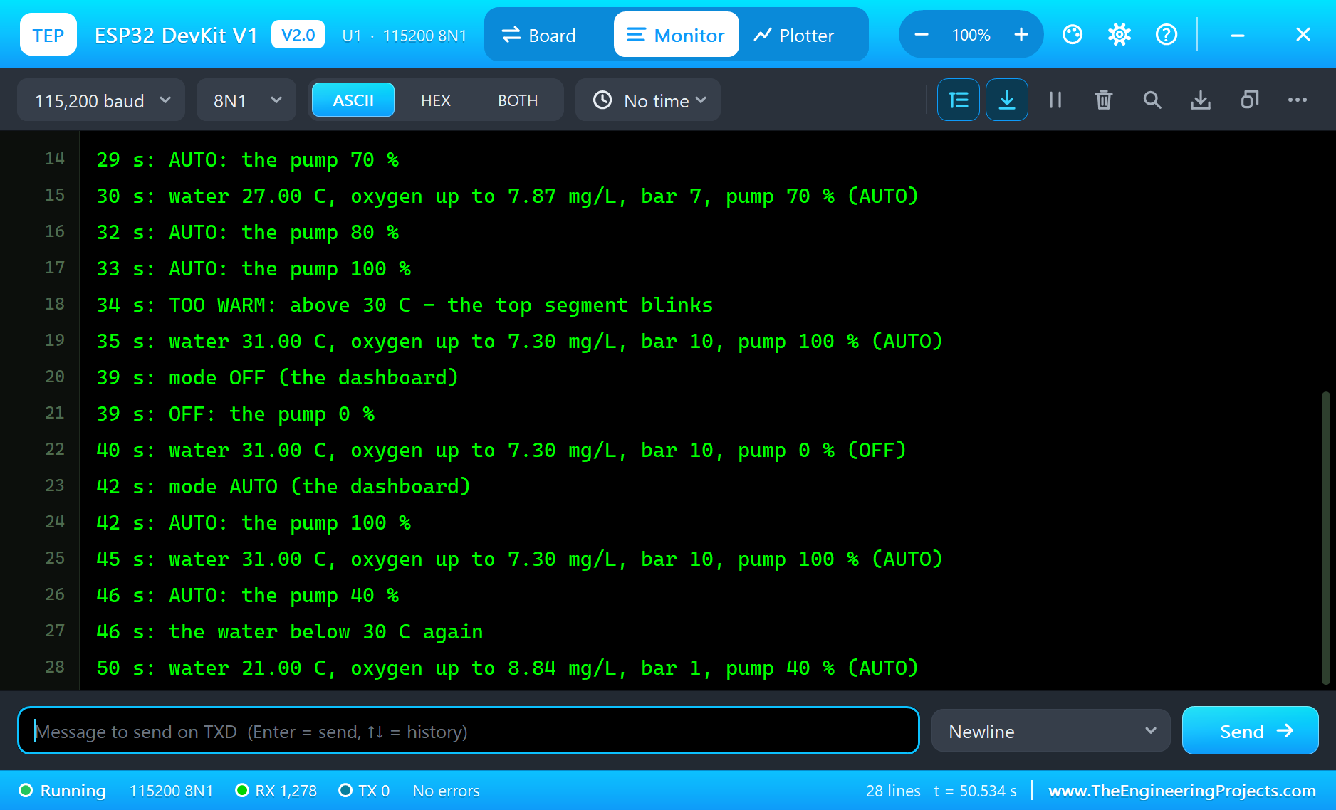
Here is the run that made the screenshots of this tutorial, 50.6 seconds of simulation. The times are the sketch's own, the seconds since the ESP32 started, as it printed them on its serial monitor; the volts, flows and currents come from the parts' pop-ups.
A Healthy Tank at 24 Degrees
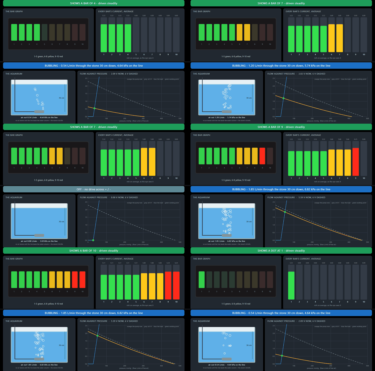
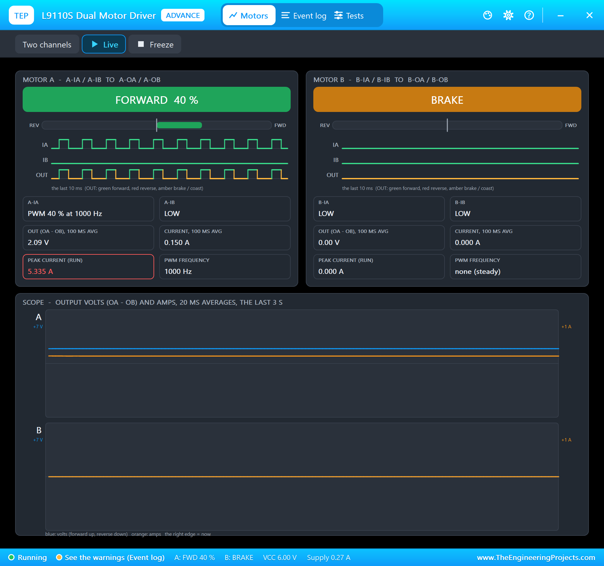
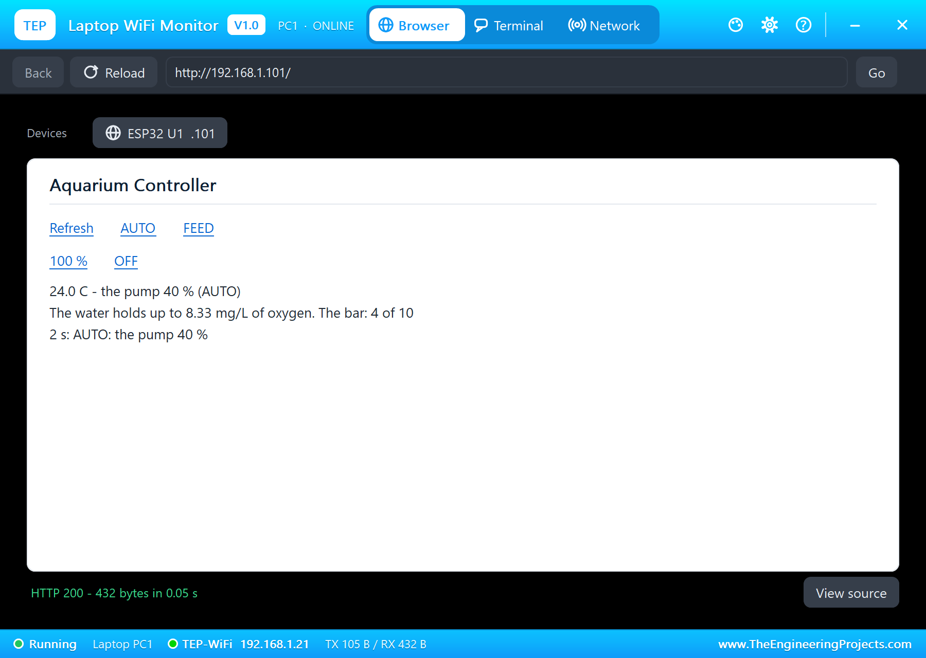
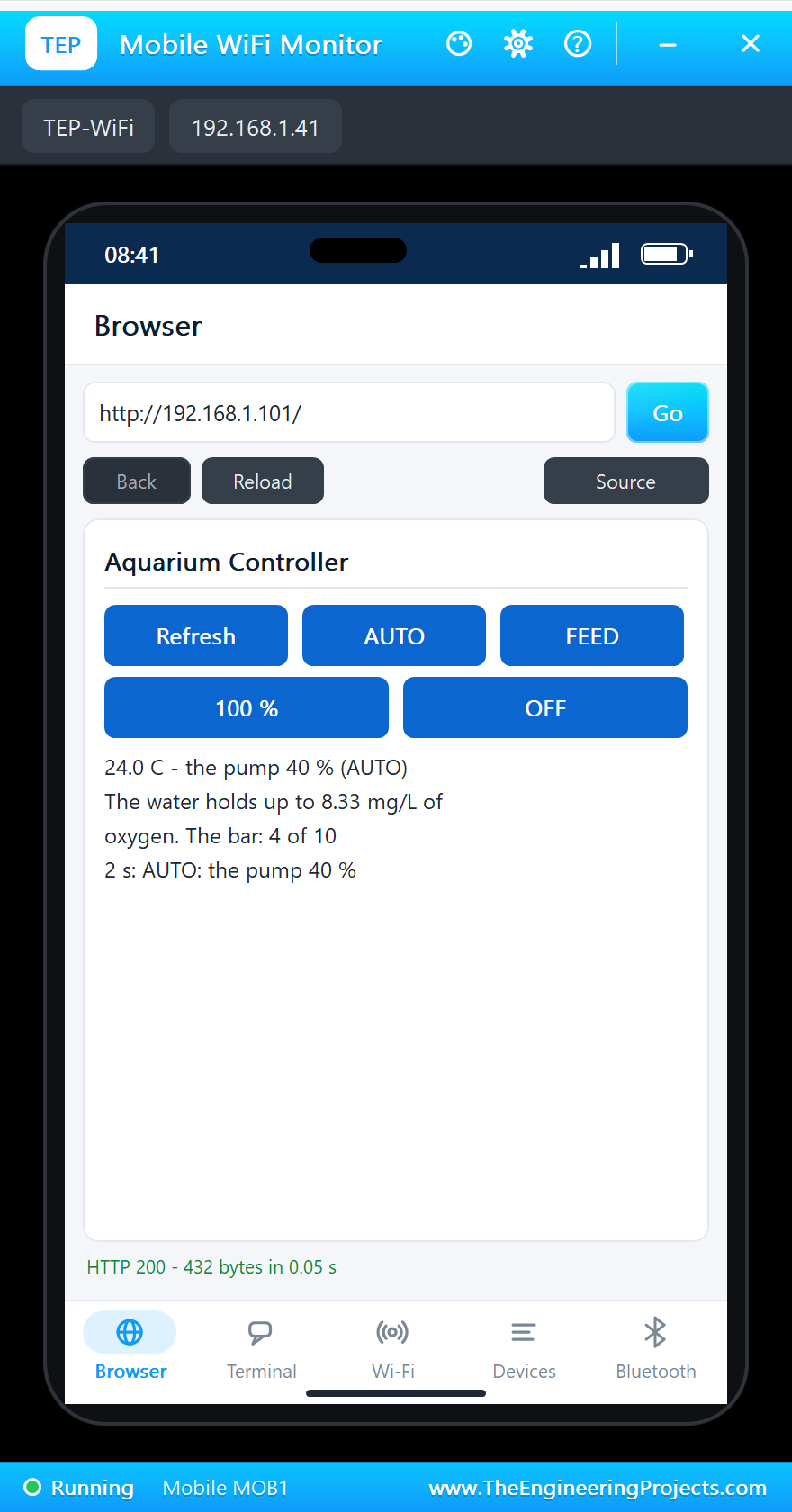
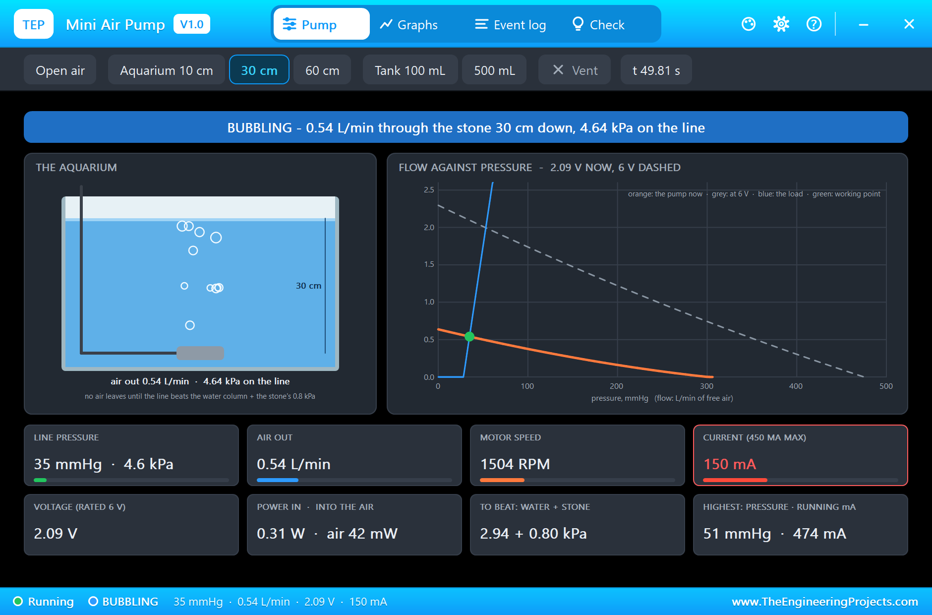
The water starts at 24 degrees, so AUTO runs the pump at its minimum, 40 %: "AUTO: the pump 40 %". Through the L9110S, the pump gets 2.09 V on average, turns at about 1,500 r/min, draws 150 mA and blows 0.54 litres a minute through the stone, with 35 mmHg on the line. The bar shows four green segments: U2 latched 0x0F, and each segment takes 5.5 mA. The dashboard adds that water at 24 degrees can hold up to 8.33 mg/L of oxygen.
The Water Warms to 27 Degrees
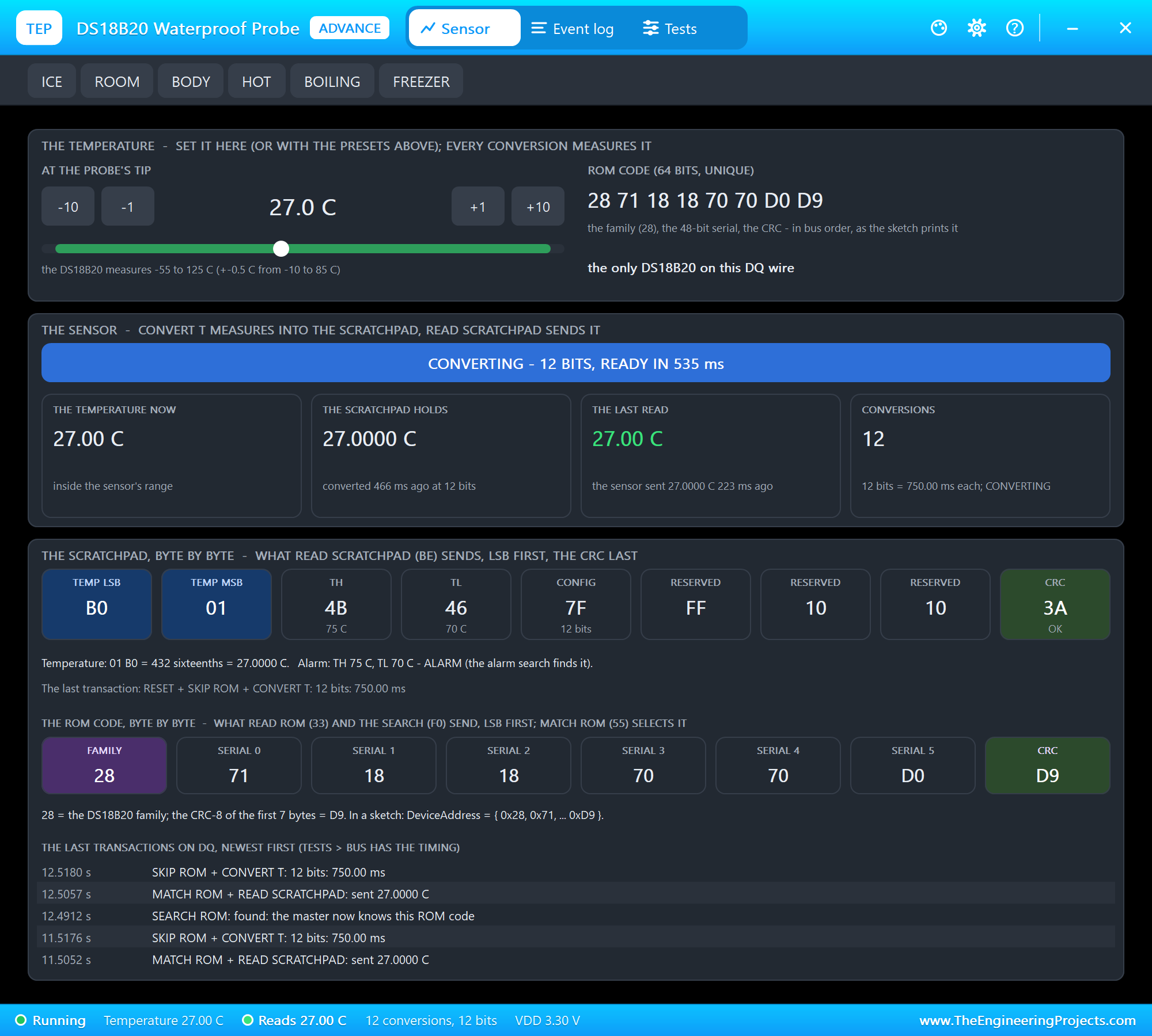
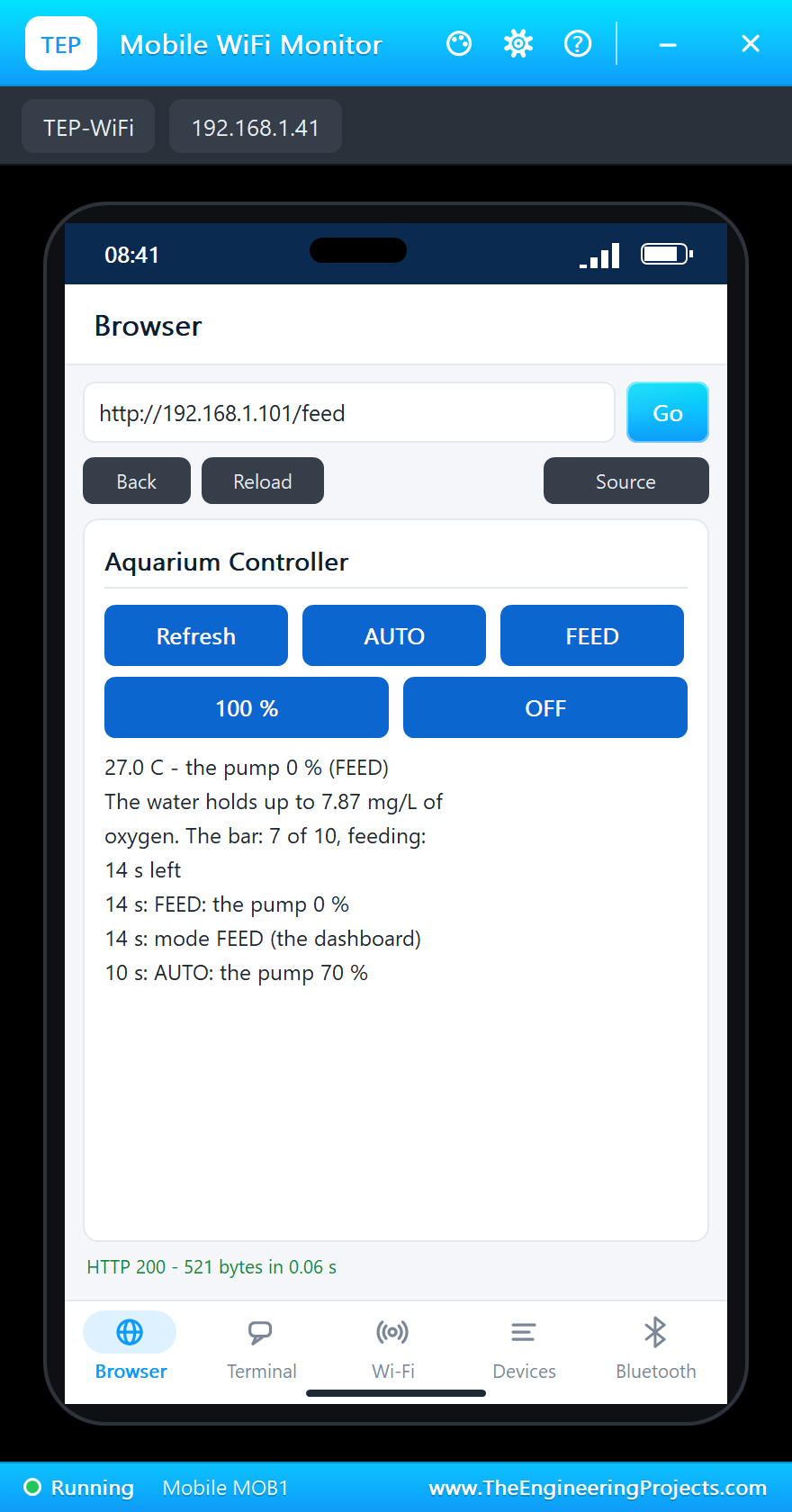
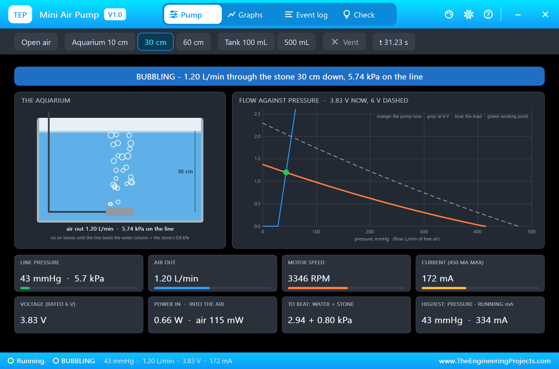
At 8 seconds, +1 in the DS18B20's pop-up three times warms the water to 27 degrees. A second later each new reading arrives: 25 degrees and 50 %, then 27 degrees and 70 %. The pump now gets 3.83 V and blows 1.20 litres a minute at 43 mmHg. The bar climbs to seven segments, five green and two yellow, and U2 latches 0x7F, drawing 39.4 mA through its VCC pin. The water can now hold only 7.87 mg/L of oxygen, which is why the pump works harder.
Feeding Time
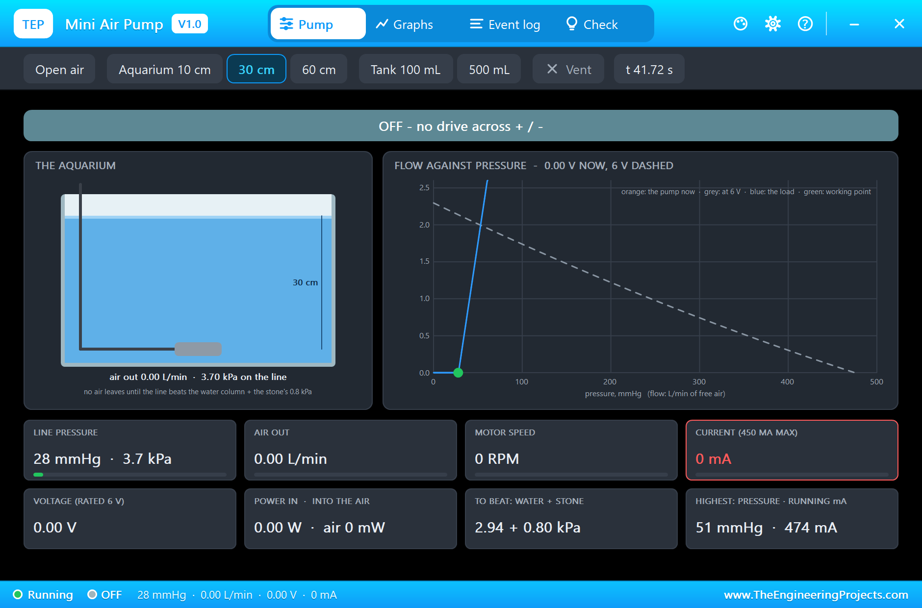
At 14 seconds, FEED on the phone stops the pump: "FEED: the pump 0 %". The bubbles stop at once, and the air line keeps 28 mmHg of pressure, the water column and the stone holding it. The dashboard counts the 15 seconds down. At 29 seconds: "feeding over: AUTO again", and the pump is back at 70 %.
Too Warm: 31 Degrees
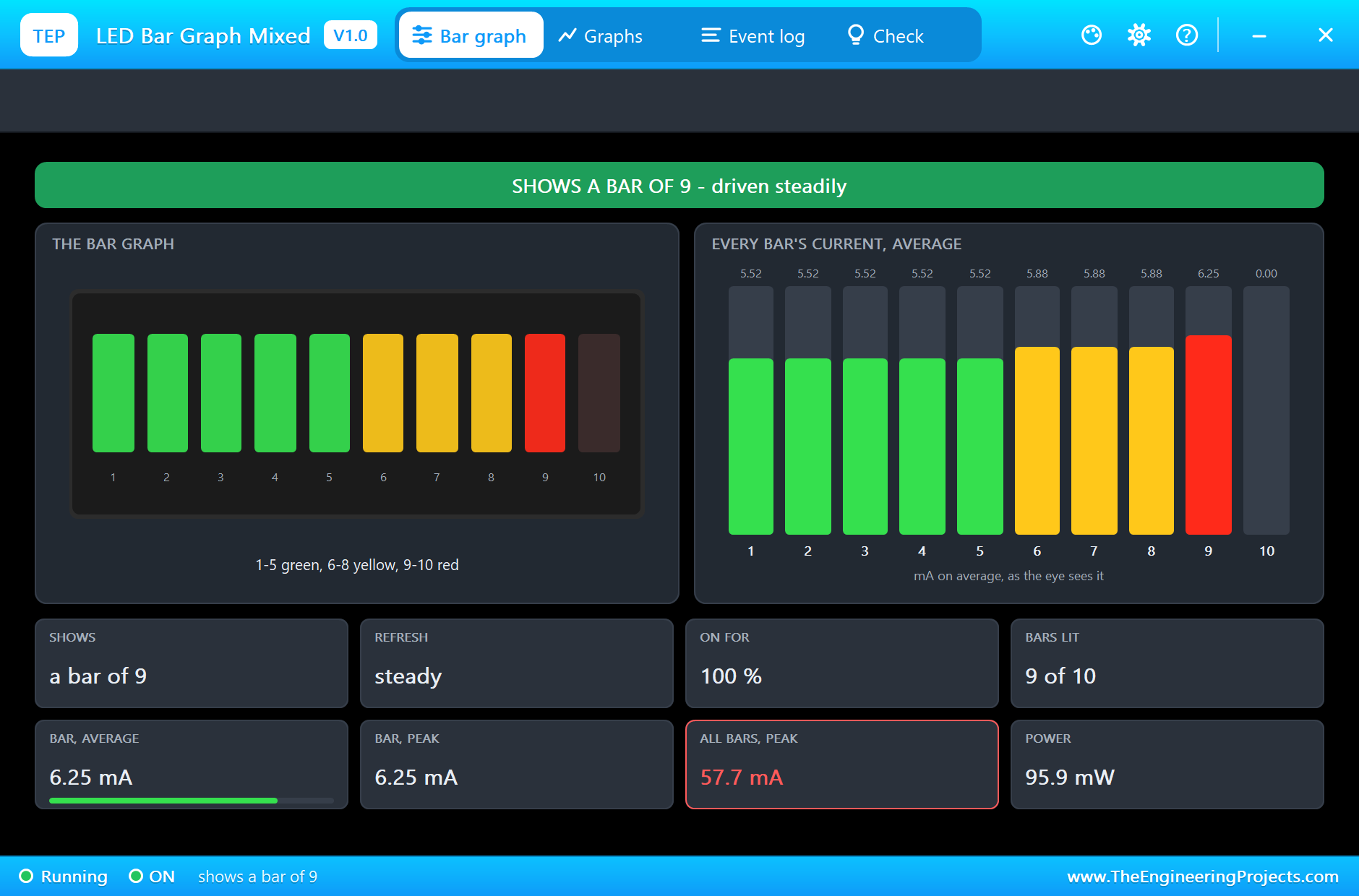
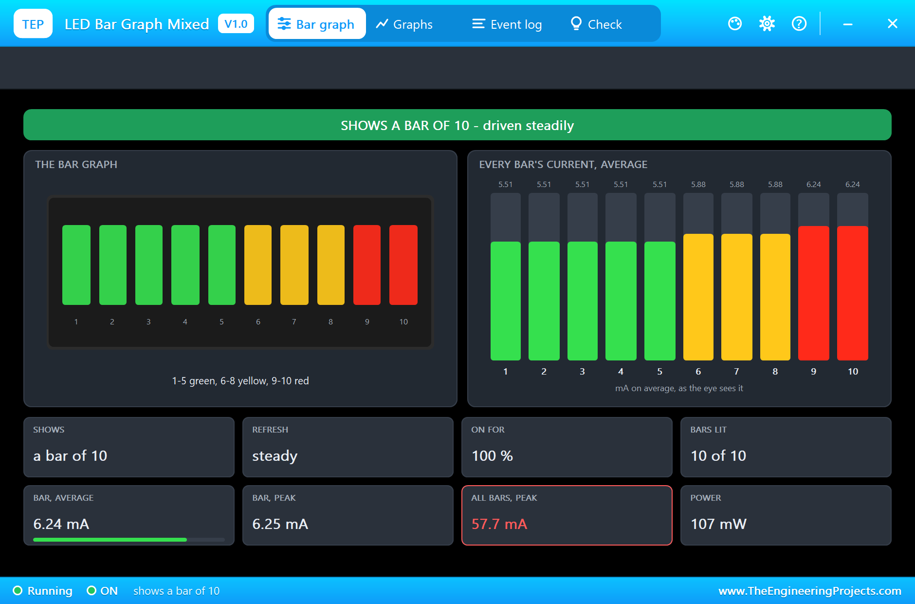
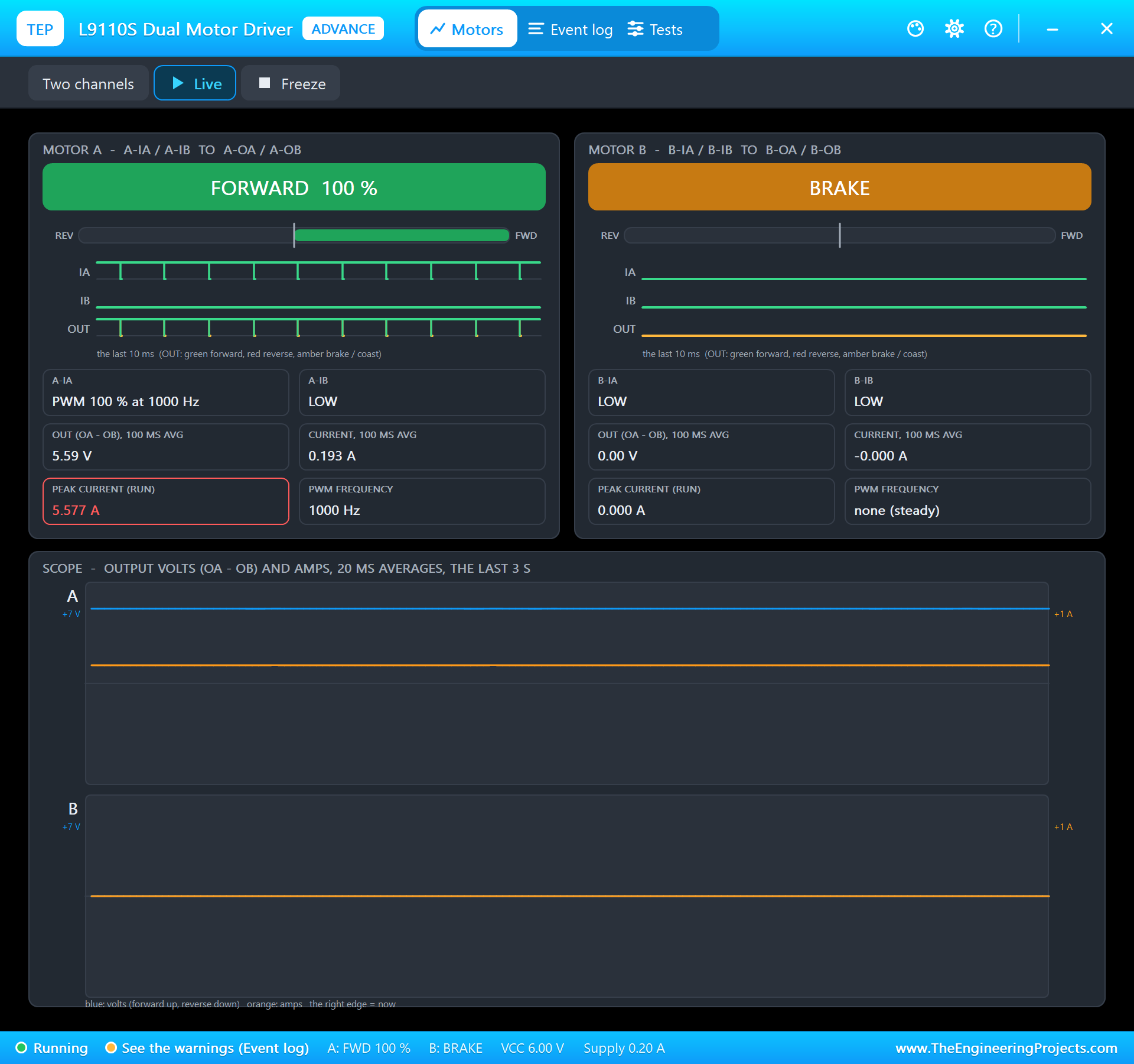
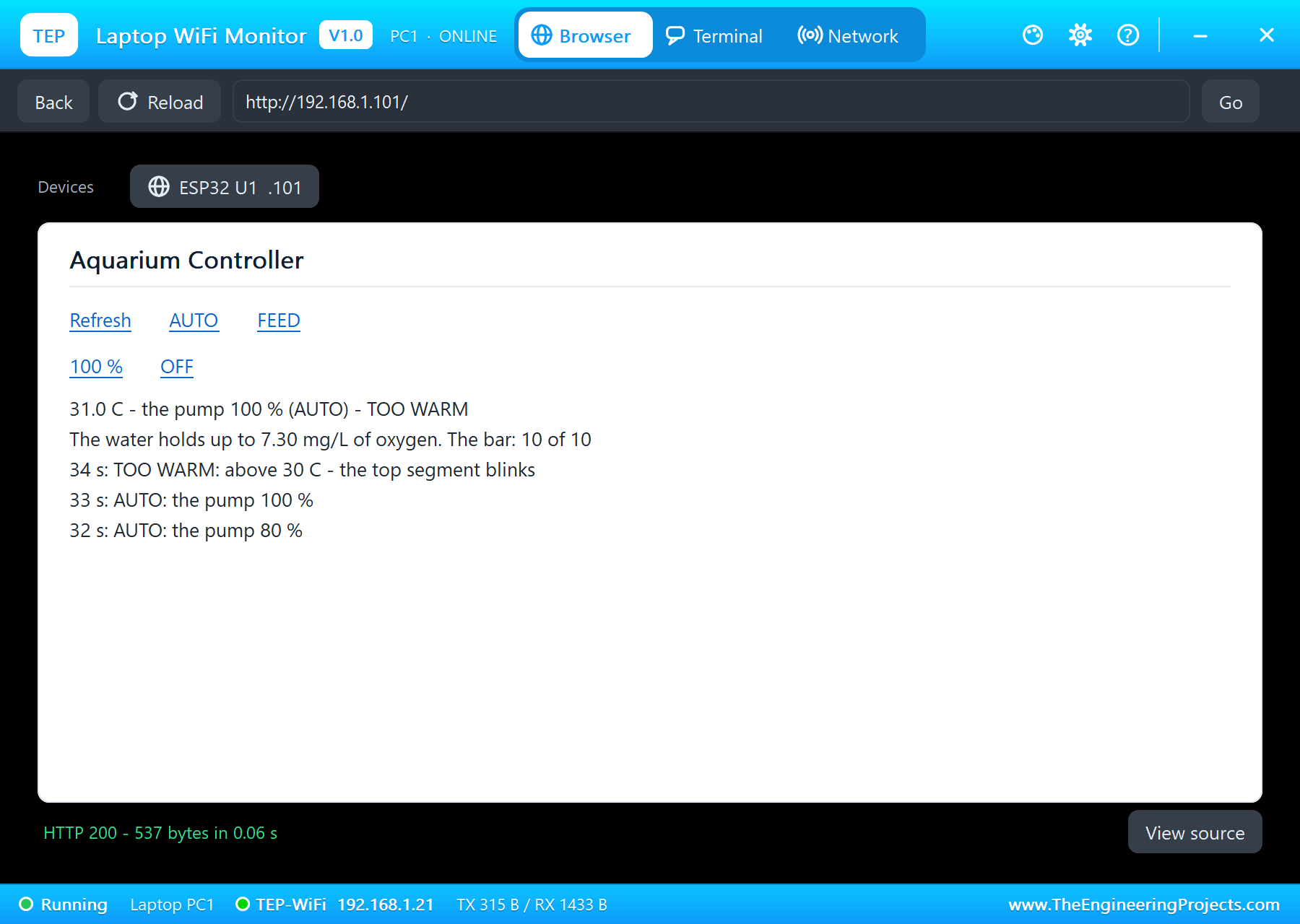
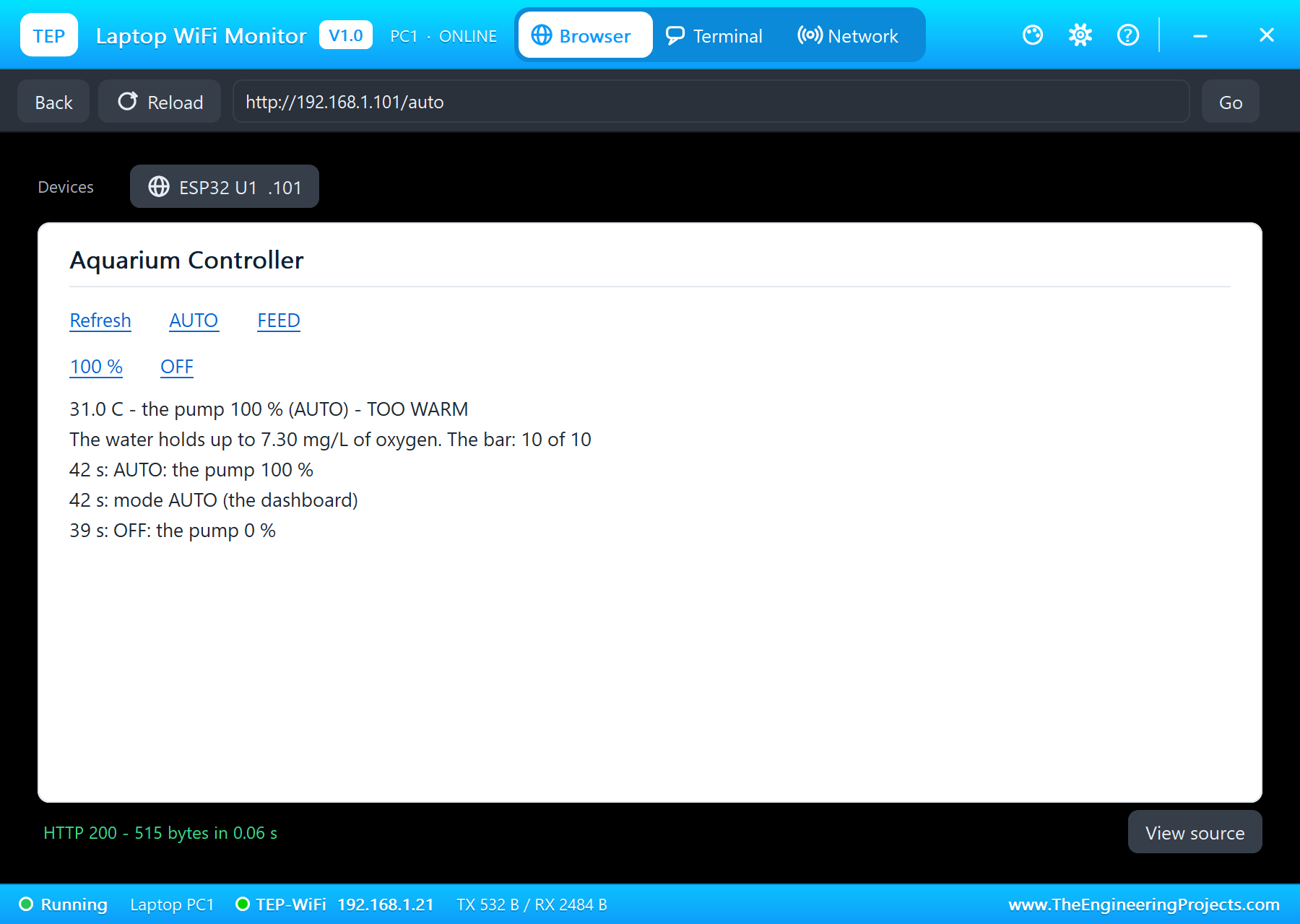
At 32 seconds, four more clicks take the water to 31 degrees. The pump climbs through 80 % to 100 %: 5.59 V, 193 mA and 1.85 litres a minute at 51 mmHg, its full output. At 34 seconds the sketch prints "TOO WARM: above 30 C - the top segment blinks". The bar alternates between nine and ten segments every half second; U3, the second chip, latches 0x01 and 0x03 in turn. The red segments take 6.25 mA each. The water can hold only 7.30 mg/L now.
OFF and AUTO from the Dashboard
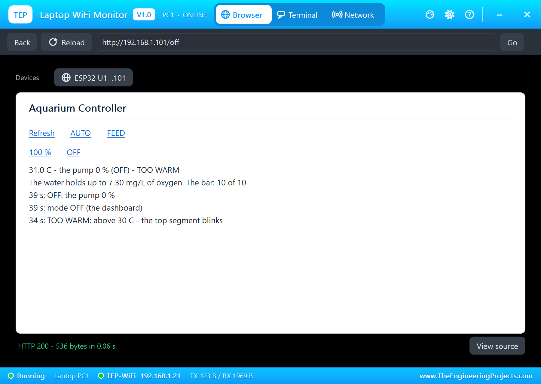
At 39 seconds OFF on the laptop stops the pump whatever the temperature, for cleaning the tank or changing the water; at 42 seconds AUTO brings it straight back to 100 %, because the water is still at 31 degrees.
The Water Cools Down
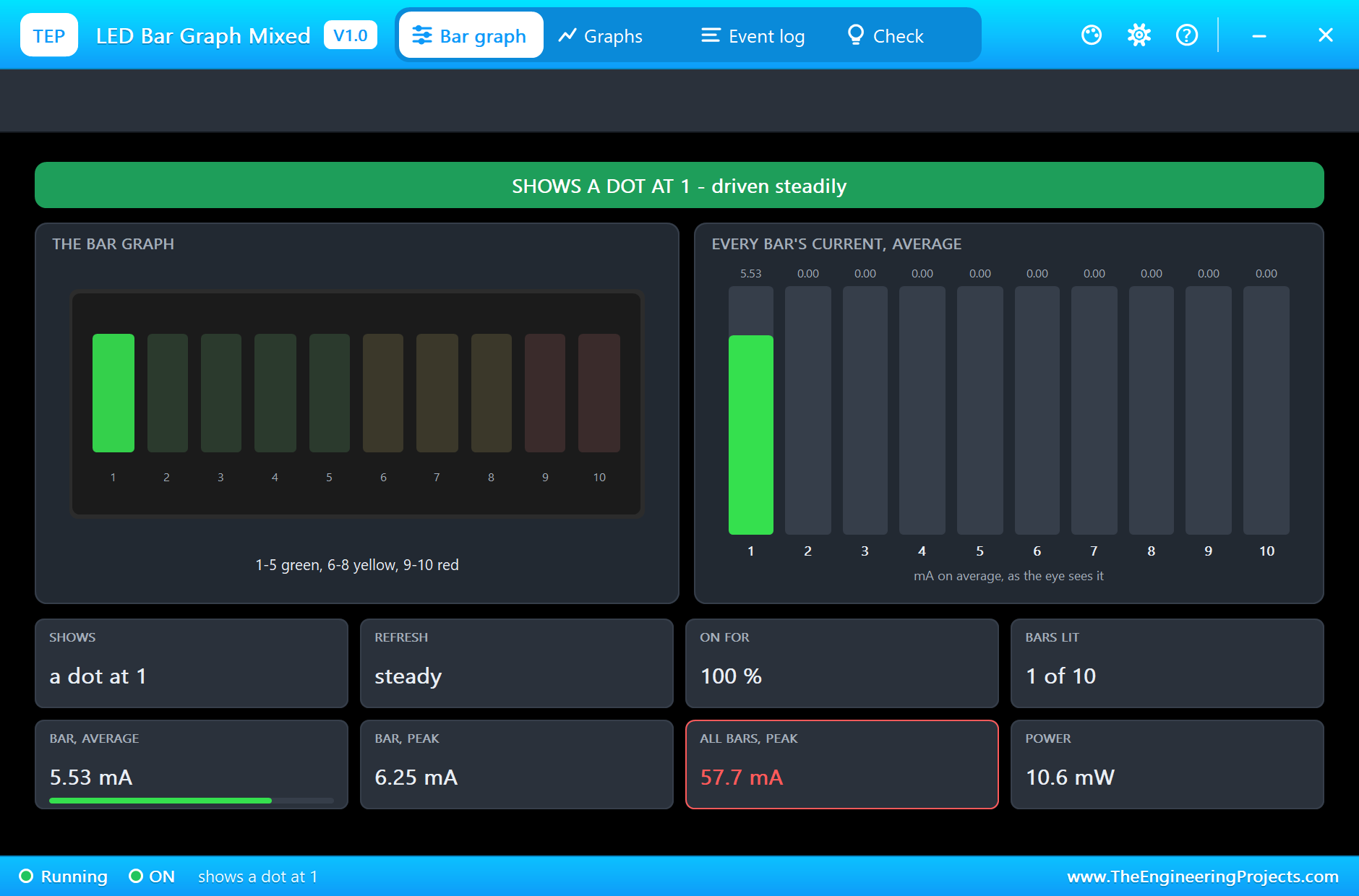
At 45 seconds, -10 in the probe's pop-up drops the water to 21 degrees. A second later the sketch prints "the water below 30 C again", the bar shows a single green segment, and the pump falls back to its 40 % minimum. Cool water holds 8.84 mg/L of oxygen.
The Numbers of the Run
| Water | Bar | Pump | Pump volts, current | Air through the stone | Oxygen it can hold |
|---|---|---|---|---|---|
| 24 C | 4 (0x0F) | 40 % | 2.09 V, 150 mA | 0.54 L/min at 35 mmHg | 8.33 mg/L |
| 27 C | 7 (0x7F) | 70 % | 3.83 V, 172 mA | 1.20 L/min at 43 mmHg | 7.87 mg/L |
| 27 C, FEED | 7 | 0 % for 15 s | 0 | none, 28 mmHg held | 7.87 mg/L |
| 31 C | 9 / 10, blinking | 100 % | 5.59 V, 193 mA | 1.85 L/min at 51 mmHg | 7.30 mg/L |
| 21 C | 1 | 40 % | 2.09 V, 150 mA | 0.54 L/min at 35 mmHg | 8.84 mg/L |
Download the Project Files
Click the button below to download IoT-Aquarium-Controller-ESP32-Proteus-Simulation-v1.0.zip (about 4.6 MB, without the source code of the models):
IoT Aquarium Controller with ESP32 - Proteus Simulation V1.0- Proteus Simulation: ESP32-Aquarium-Controller.pdsprj, the compiled HEX file and copies of the models.
- Arduino Code: ESP32_Aquarium_Controller.ino, the complete sketch.
- Proteus Library Files: the LIB files of the ESP32 DevKit V1, the 74HC595, the LED bar graph, the air pump, the DS18B20, the L9110S, the resistor and the two WiFi Monitors.
- Proteus Model Files: the DLL models.
- README.txt: the installation steps, the properties, the test results and the links to every library post.
No Proteus yet? Read How to Download and Install Proteus 7 and 8. New to libraries? Follow How to Install a New Library in Proteus.
How to Install the Project Files
- Close Proteus and extract the whole zip file, for example to your Desktop.
- Copy the files from Proteus Library Files into the LIBRARY folder of Proteus.
- Copy the files from Proteus Model Files into the MODELS folder.
- Start Proteus and open the project from the Proteus Simulation folder.
Changing the Code
Open the sketch in the Arduino IDE with the ESP32 boards installed and the OneWire and DallasTemperature libraries from the Library Manager, compile it, export the compiled binary and set the board's PROGRAM property to the new file. The temperatures, the minimum power and the feeding time are at the top. The same sketch runs on a real ESP32 DevKit V1. For our other ESP32 water project, with a DS18B20, a TDS meter and a turbidity sensor, see the IoT Water Quality Monitoring System with ESP32.
Ideas to Extend the Project
- Add a heater with a relay and hold the water at 25 degrees.
- Switch the tank's light on a day and night timetable.
- Feed the fish automatically with a servo-driven feeder at set times.
- Send a message to the owner's phone when the water is too warm.
- Use the second 74HC595's six free outputs for status LEDs.
- Dim the bar at night with PWM on the 74HC595s' OE pin.
From Simulation to Real Hardware
- Mind the 74HC595's supply current: 70 mA through VCC at most; U2's eight segments take about 45 mA, so do not lower the 220 ohm resistors much.
- Power the shift registers from 3.3 V: then the ESP32's 3.3 V signals are proper logic levels for them.
- Keep the probe in the water, not the electronics: the DS18B20 probe is sealed; the rest belongs in a dry box away from splashes.
- Give the pump its own supply: a 6 V pump draws a few hundred milliamps at start; the L9110S switches it, the ESP32 only sends the PWM.
- Fit a check valve: when the pump stops, water can creep back up the air line into it; a one-way valve in the line stops that.
Troubleshooting
- The bar stays dark: SRCLR held low clears the shift registers, OE high switches the outputs off, or RCLK is never pulsed after the bytes.
- Segments 9 and 10 stay dark: U3's data line D21 is not wired, or its byte is not put on SER2 during the eight clocks.
- The temperature reads 85 degrees at the start: the scratchpad read before the first conversion finished.
- The temperature reads -127: no DS18B20 on D4, or the 4.7 k pull-up is missing.
- No bubbles at low power: the pump must beat the water column and the stone; keep at least 40 %.
Limitations of the Simulation
- The water's temperature comes from the DS18B20's pop-up; the tank does not warm or cool by itself.
- The oxygen figure is the most the water can hold at that temperature, from a standard formula; there is no oxygen sensor.
- The network is simulated: the dashboard travels between the ESP32 and the two monitors inside Proteus; the times in this tutorial are simulation time.
- ESP32 is made by Espressif; the DS18B20 by Analog Devices (Maxim); the 74HC595 by several companies. This project is not made or endorsed by them or by Labcenter.
So, that was all about the IoT Aquarium Controller with ESP32 - Proteus Simulation. I hope it helps you build your own tank controller: a DS18B20 for the water, two 74HC595 shift registers that turn four pins into a ten-segment bar graph, an air pump whose speed follows the oxygen the water can hold, a feeding pause and a too-warm alarm, all tested in a simulation before you wet a single wire. More IoT projects with the ESP32 and the Raspberry Pi 5 are coming in this series. If you have any questions, ask in the comments and I will help you out. Till the next tutorial, take care and have fun!

Comments
0