


12V LiFePO4 Battery Library for Proteus Simulation


Hello friends, I hope you all are doing great. Today, I am going to share the new 12V LiFePO4 Battery Library for Proteus Simulation, the next library of our renewable energy series. If you have searched for a Proteus simulation of a LiFePO4 battery, the lithium iron phosphate battery that is replacing the old 12 V lead-acid blocks everywhere, this library brings it into Proteus together with the part that makes it safe: its battery management system, the BMS.
12V LiFePO4 Battery Library for Proteus Simulation
Latest version: V1.0 (November 2026, this tutorial)
Helping Tools
- Serial Monitor Advance: a serial terminal window for the UART of your board
- Serial Monitor Expert: the serial monitor with extra debugging tools
- LCD Library for Proteus V3.0: 16x2, 20x4 and I2C LCDs to show your readings
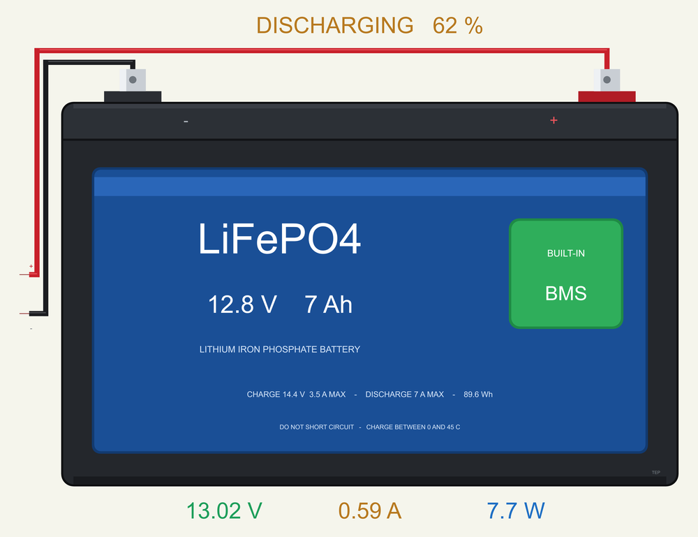
The battery is drawn at its true size, and at run time it writes what it is doing and the charge it has left above itself, and its volts, amps and watts under itself on your sheet. The simulation model follows the flat voltage curve of real LiFePO4 cells, counts every ampere second that flows in or out, and has a BMS that cuts the load off when the battery is empty and stops a charge that goes too far. In the demo a small load empties the battery, the BMS cuts it off, and our hand crank generator charges it back, while an Arduino counts the amp-hours through our INA219.
NOTICE: Our team has put a lot of effort into these small parts: the bodies, the animation and the pop-ups are all our own design, and you get them free. Your feedback is the fuel that keeps us going, so please tell us what you think in the comments below or in the Motor Driver board of our forum. And if our free libraries help you, you can buy us a coffee. So, let's get started with the 12V LiFePO4 Battery Library for Proteus Simulation:
What is a LiFePO4 Battery?
LiFePO4 is short for lithium iron phosphate, the material of the positive electrode. It is a lithium-ion battery, but a calm one. A single cell gives about 3.2 V, a little less than the 3.7 V of the cells in a phone, and stores a little less energy for its weight. In exchange it is far harder to set on fire, it survives two thousand deep cycles, and it does not mind being left half charged. Four cells in series make 12.8 V, which is close enough to a 12 V lead-acid battery to take its place.
That is exactly what the battery of this library is: four cells and a BMS in the case of the common 12 V 7 Ah sealed lead-acid battery, the one inside alarm panels, gate motors, small UPS units and solar lights. It weighs under a kilogram where the lead-acid one weighs more than two, it gives almost its whole capacity where lead-acid gives half, and it lasts several times as long. People use these batteries to store the energy of small solar panels and wind turbines, which is why this one belongs in our renewable energy series.
| 12.8 V 7 Ah LiFePO4 battery (a maker's sheet) | |
|---|---|
| Nominal voltage | 12.8 V (four cells in series) |
| Capacity | 7 Ah, 89.6 Wh |
| Internal resistance | 100 milliohm at most |
| Charge | 14.4 V, 1.4 A standard, 3.5 A at most |
| Discharge | 3.5 A standard, 7 A continuous, 10 A for 15 minutes |
| Discharge cut-off | 10.0 V |
| Charge cut-off (BMS) | 3.9 V a cell |
| Temperature | charge 0 to 45 °C, discharge -20 to 60 °C |
| Life | 2000 cycles to 80 % depth of discharge |
| Size | 151 x 65 x 94 mm, about 0.9 kg |
The Flat Voltage Curve and the State of Charge
The voltage of a LiFePO4 battery hardly moves while it works. A full battery rests at about 13.6 V. Take a tenth of its charge out and it shows 13.3 V; take out another six tenths and it still shows 13.0 V. Only below 20 % does the voltage begin to fall in earnest: 12.9 V at 20 %, 12.0 V at 10 %, and then steeply down to 10.0 V when the battery is empty. This flat middle is a gift to the load, which sees a steady supply, and a problem for anyone who wants to know how much charge is left.
With a lead-acid battery you can read the state of charge from a voltmeter. With LiFePO4 you cannot: between 20 % and 90 % the whole answer hides in four tenths of a volt, less than the drop that a load causes. The only good fuel gauge is to count. Every ampere that flows out for an hour takes one amp-hour from the battery, and every ampere that flows in for an hour puts one back. This is called coulomb counting, and both the simulation model and the demo sketch do it.
The model stores the charge as a number and moves it with the current, and the voltage follows from the curve. Behind the curve sits the internal resistance of the pack, 80 milliohm, which grows when the battery is nearly empty or cold. A real 7 Ah battery needs hours to empty and to fill, so the SPEED property runs the battery clock faster: at 3600 one simulated second is one hour for the battery, and a whole discharge fits into a few seconds of simulation.
What the BMS Does
A lithium cell must never be charged too high or emptied too far, so every LiFePO4 battery of this kind carries a small circuit board that watches the cells and can switch the battery off. In this simulation the BMS does four things. It cuts the load off when the pack falls to 10.0 V. It stops the charge when a cell reaches 3.9 V. It opens when more than 20 A flows. And it refuses a charge below 0 °C, because charging a frozen lithium cell damages it.
The important detail is that the two switches of a real BMS work one way each. One blocks the discharge, the other blocks the charge. A battery that was cut off because it is empty therefore still accepts a charge, and a battery that refuses more charge still feeds a load. The model has both blocks, each on its own. A cut-off battery shows no voltage of its own at its terminals, which makes many people think it is dead. It is not: connect a charger, and when the cells are back at 12.0 V the BMS closes again by itself.
The end of the charge is modelled too. Over the last 5 % the cells take current less and less willingly. With a proper 14.4 V charger the charge current simply tapers away to nothing. A source without a voltage limit keeps pushing instead, the voltage climbs fast, and at 15.6 V the BMS steps in. The BMS is the last line of defence, not the charger.
Features of the 12V LiFePO4 Battery Library for Proteus Simulation
- The battery at true scale: the black case, 151 x 94 mm, with its blue label and two blade terminals; at run time the state and the charge left are written above it and the volts, amps and watts under it.
- The flat LiFePO4 curve: 13.6 V full, about 13.2 V through the middle, 12.0 V at 10 % and 10.0 V empty, behind 80 milliohm.
- A charge counter with a clock: the charge left follows the current, in real time or up to 7200 times faster.
- A real BMS: a discharge cut-off at 10.0 V, a charge cut-off at 3.9 V a cell, an over-current trip at 20 A and temperature limits, each block one-way.
- A charge that tapers: the last 5 % go in slowly, as in a real cell.
- The charge in your hands: the SOC property and chips in the pop-up (Full, 50 %, 20 %, 5 %), the clock and a BMS reset.
- A pop-up: the four cells and the BMS with the direction of the current, the voltage curve with its three limits and the working point, eight live values, graphs, an event log and a check page.
- A complete package: about 1.6 MB with the library, our hand crank generator, our Arduino UNO V4.0 and the demo, without the source code of the model.
The LiFePO4 Battery in Proteus
The device is LIFEPO4BAT12V7TEP in TEPLIFEPO4.LIB, under Electromechanical > Batteries, with the prefix BAT and the analog model TEPLIFEPO4.DLL. Search LIFEPO4 in Pick Devices. Its two pins are on the left, at the ends of the leads from the terminals: the red + and the black -. The properties are SOC (the charge at the start in percent), SPEED (the battery clock, 1 to 7200) and TEMP (the temperature of the battery, 25 °C). The symbol is drawn to the battery's true size against our Arduino UNO, so it is more than twice as long as the board.
Download 12V LiFePO4 Battery Library for Proteus Simulation
Click the button below to download 12V-LiFePO4-Battery-Library-for-Proteus-v1.0.zip (about 1.6 MB, without the source code of the models):
12V LiFePO4 Battery Library for Proteus V1.0- README.txt: installation, the demo, the wiring, troubleshooting and the limits of the simulation.
- Proteus Library Files:
TEPLIFEPO4.LIB,TEPCRANK.LIBandArduinoV4TEP.LIB. - Proteus Model Files:
TEPLIFEPO4.DLL,TEPCRANK.DLLandTEPARDUINO.DLL. - Arduino Code: the demo sketch.
- Proteus Simulation: the demo project, its HEX file and copies of the DLLs.
No Proteus yet? Read How to Download and Install Proteus 7 and 8. New to libraries? Follow How to Install a New Library in Proteus.
How to Install 12V LiFePO4 Battery Library for Proteus Simulation
- Close Proteus and extract the whole zip file, for example to your Desktop.
- Copy the files from Proteus Library Files into the LIBRARY folder of Proteus.
- Copy the files from Proteus Model Files into the MODELS folder.
- Delete
TEPLIFEPO4.IDXfrom the LIBRARY folder if it is there. - The demo also uses our INA219 Current Sensor Library for Proteus: install it from its own package (it is not in this zip).
- Start Proteus, press P and search for LIFEPO4.
Proteus Simulation of the LiFePO4 Battery with Arduino
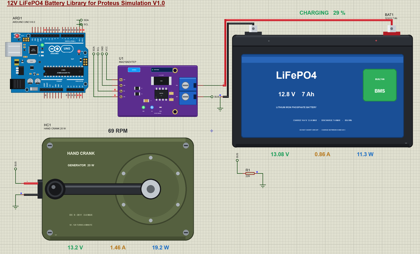
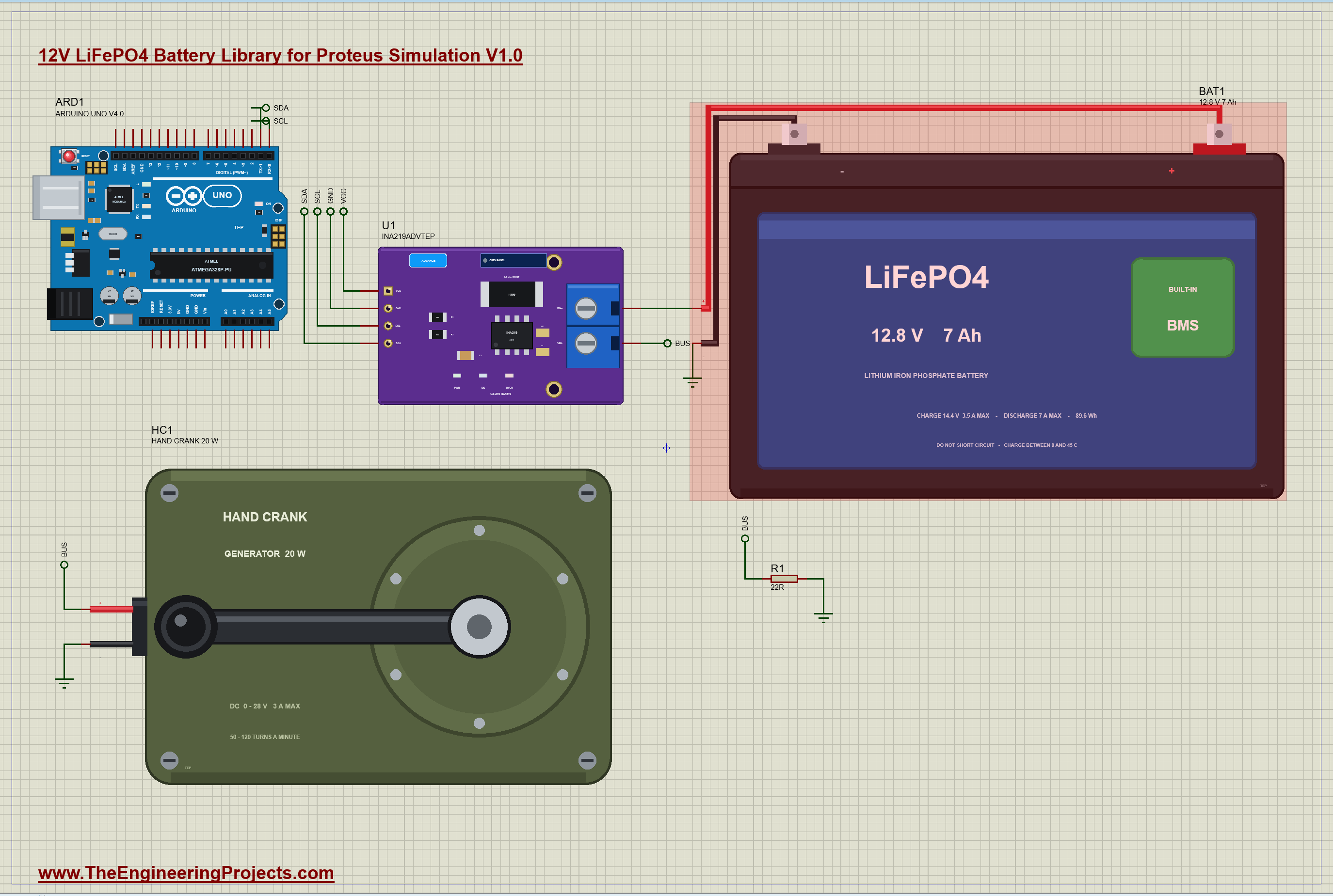
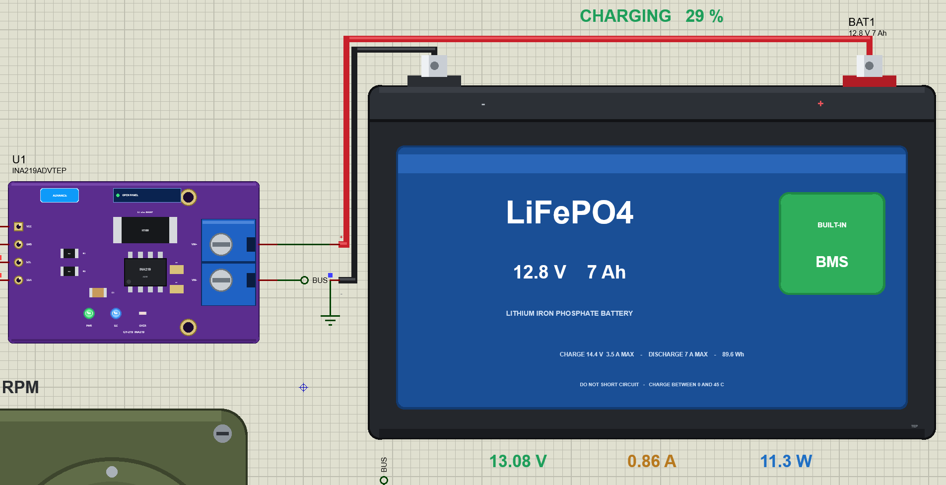
The demo has our Arduino UNO Library for Proteus V4.0 with its built-in monitor, the same window as our TEP Serial Monitor Advance for Proteus, on an A3 sheet. The battery, BAT1, starts almost empty, with 5 % of its charge, and its SPEED is 3600, so one simulated second is an hour for the battery. Its + goes through the 0.1 ohm shunt of our INA219 (U1, its pop-up version) to a net called BUS. Two things sit on that bus: a 22 ohm resistor (R1), which stands for a 12 V lamp of about 7 W, and our hand crank generator (HC1) from the Hand Crank Generator Library for Proteus Simulation, which is the charger. The crank follows its own demo: 30 turns a minute from 0.3 s, 60 from 2.3 s, 90 asked from 4.3 s, 60 again from 6.3 s, and the hand lets go at 8.3 s. Its rectifier keeps the battery from turning the handle. Open LiFePO4-Battery-Crank-INA219-ArduinoUnoV4.pdsprj.
The Sketch
The INA219 sits between the battery and the bus, so it sees the battery's current in both directions. The sketch reads its two voltage registers straight over I2C, with no library. The shunt register is signed:
  const float busV = ((uint16_t)readReg(0x02) >> 3) * 0.004;    // 4 mV a step: the bus, after the shunt
  const float shuntV = readReg(0x01) * 0.00001;                 // 10 uV a step, signed
A current out of the battery comes out positive and a current into it negative, and the battery's own voltage is the bus plus the shunt's drop:
  amps = shuntV / SHUNT_OHM;                                     // + out of the battery, - into it
  volts = busV + shuntV;                                         // the battery's own terminals
Twenty times a second the sketch adds the current into its coulomb counter. The constant CLOCK is 3600, the same as the battery's SPEED, so the count comes out in the battery's own amp-hours; with a real battery it would be 1:
if (lastAt) ampHours -= (amps + lastAmps) / 2 * (now - lastAt) / 1000.0 * CLOCK / 3600.0; // the coulomb counterEvery half second it prints the volts, the amps and the watts, what the battery is doing and the amp-hours lost or gained. It also recognises a battery that the BMS has cut off, by a missing current together with a voltage far too low for a LiFePO4 pack:
else if (volts < CUT_OFF_VOLTS) Serial.print(F("the BMS has cut the load off - charge the battery"));The LED on pin 13 lights while the battery is charging. You can type reset to forget the amp-hours or rate 1000 to report once a second.
LiFePO4 Battery Simulation Results
Open the project and press Run. The demo runs about 10 simulated seconds, which are ten hours for the battery; with the pop-ups open and the pictures being taken it took about three minutes on our PC. Click the battery for its pop-up. Every number below comes from one simulation run, the demo exactly as it ships.
An Almost Empty Battery
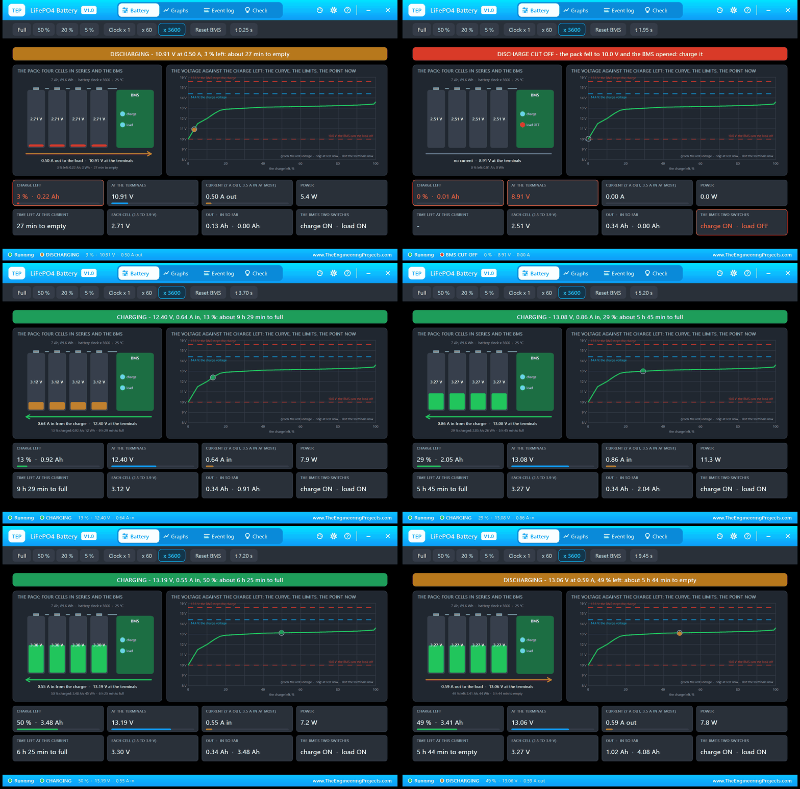
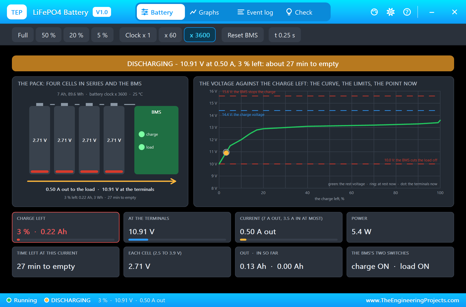
The run starts with the lamp on and nothing to charge the battery. At 0.25 s the pop-up shows 3 % left, 0.22 Ah, and the pack is already far down the steep end of its curve: 10.91 V at 0.50 A, 5.4 W into the lamp, with each cell at 2.73 V. The banner works out that the battery will be empty in about 27 minutes at this current. In the curve on the right the ring is the rest voltage and the dot is the voltage at the terminals; both sit near the bottom left corner, just above the red line of the cut-off. At 0.3 s the hand begins to turn the crank at 30 turns a minute, but that is too slow to charge anything: it only takes a little of the lamp's current off the battery.
The BMS Cuts the Load Off
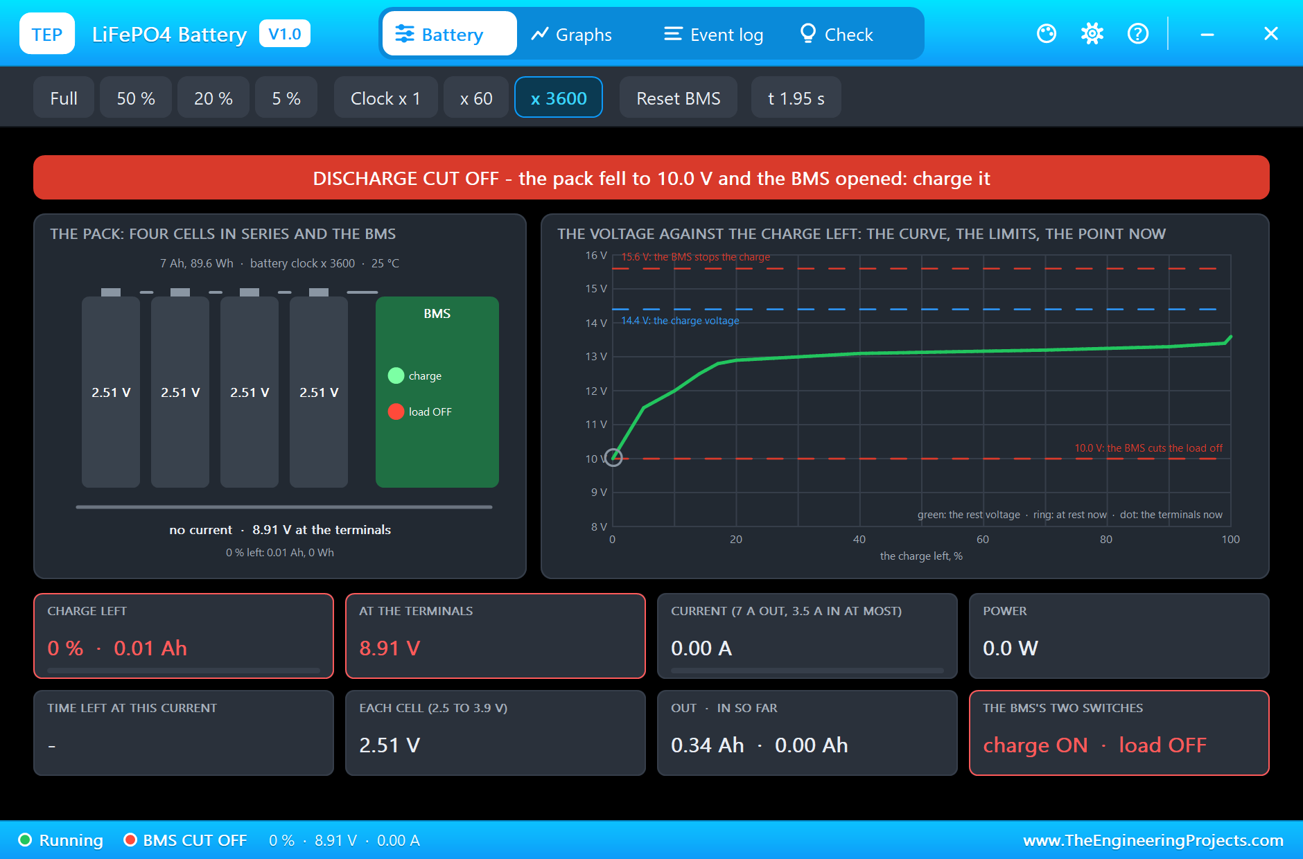
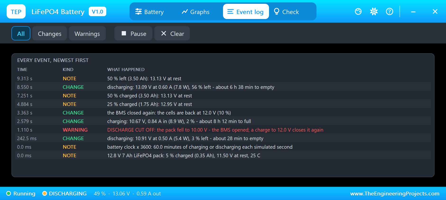
At 1.110 s the pack falls to 10.00 V, and the BMS opens. The Event log writes the warning DISCHARGE CUT OFF; the battery has given 0.34 Ah since the start. In the pop-up the lamp of the load switch turns red, the banner turns red, and the current is zero. The terminals still show 8.91 V, but that voltage does not come from the cells. It is the hand crank, at 30 turns a minute, feeding the lamp alone, and the lamp glows dimly on it. The cells rest at 2.50 V each behind the open switch. On the monitor the sketch has noticed it as well: no current and less than 11 V means the BMS has cut the load off.
Charging Through the Cut-Off
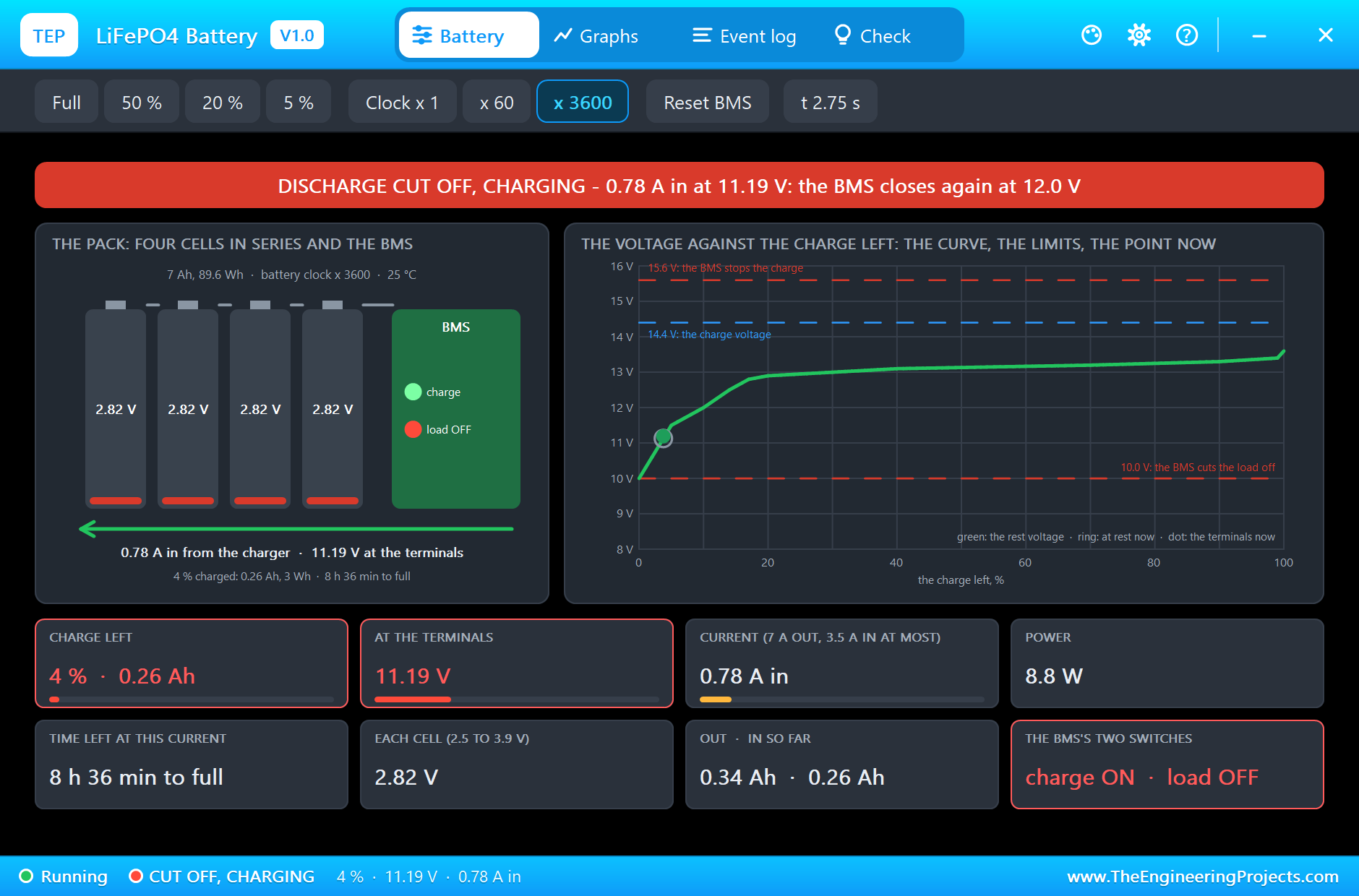
At 2.3 s the hand speeds up to 60 turns a minute. Now the crank makes more voltage than the empty cells have, and current flows into the battery although the BMS is still open for the load: 0.78 A in at 11.19 V, with each cell at 2.82 V and 4 % of charge at 2.75 s. This is the one-way block at work. The banner says it in one line: DISCHARGE CUT OFF, CHARGING. The lamp is fed by the crank all the while. At 3.363 s the cells are back at 12.0 V, which is 10 % of charge, and the BMS closes again by itself.
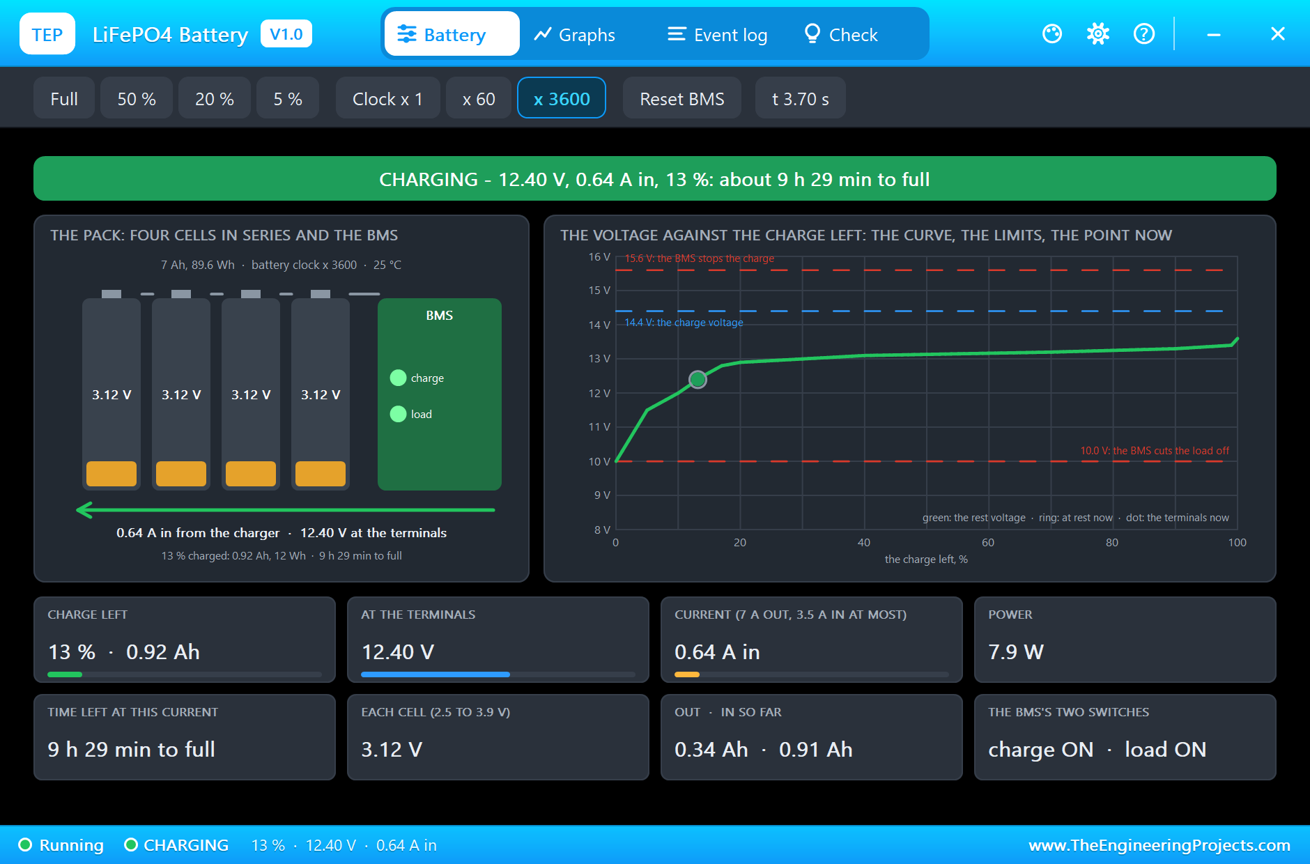
At 3.7 s both switches are on, the battery holds 13 % and takes 0.64 A at 12.40 V. The current is a little smaller than before, because the battery's voltage has risen and the crank, at the same cadence, has less voltage left over to push with.
Charging from the Hand Crank
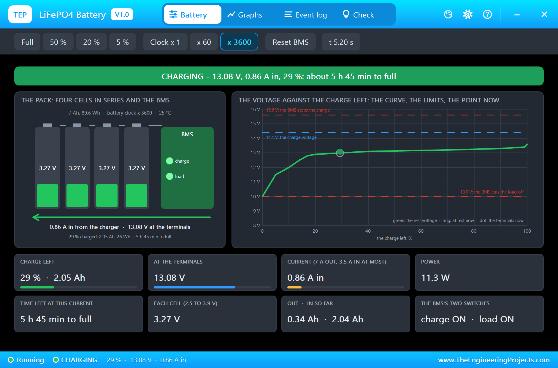
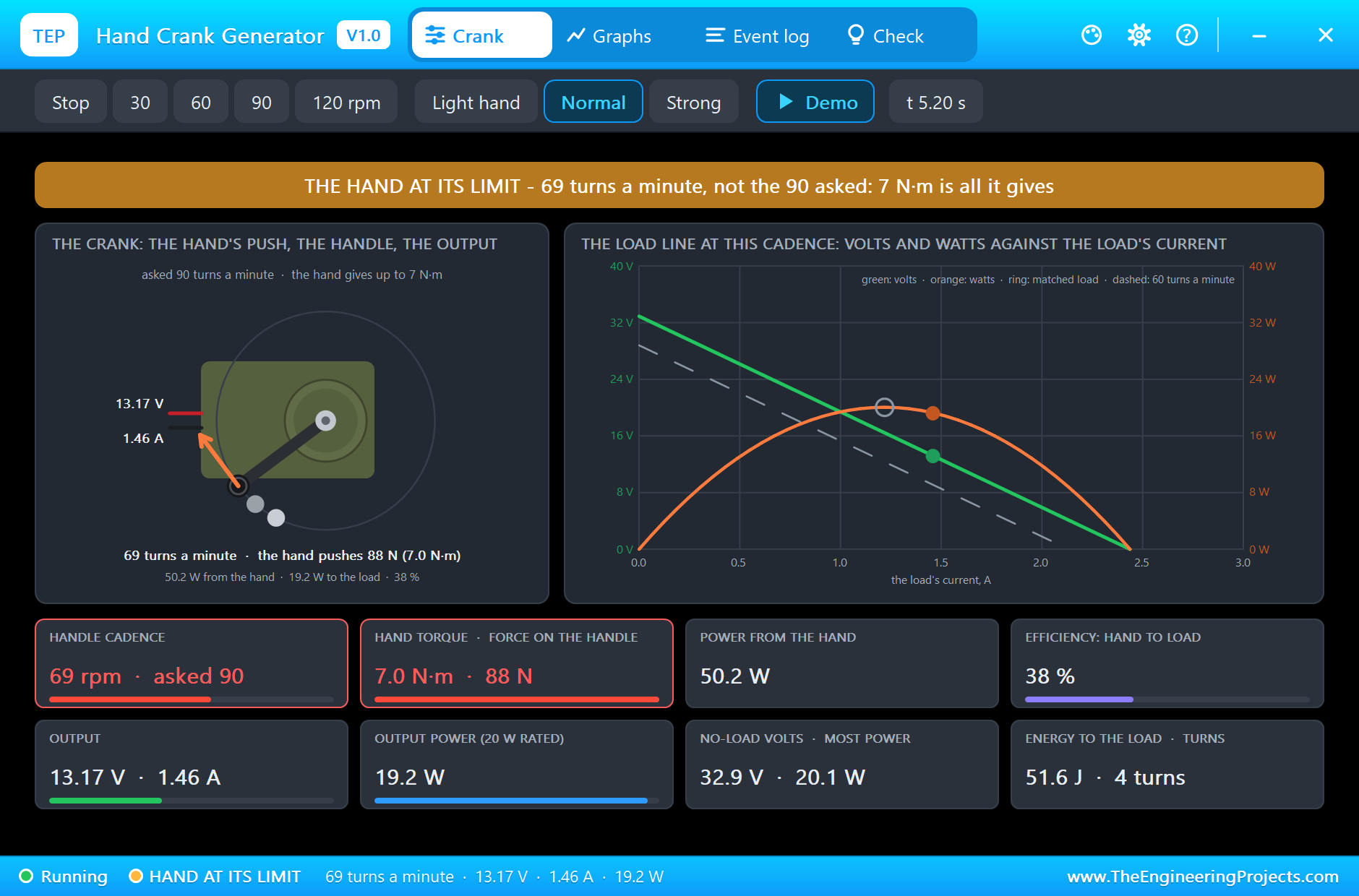
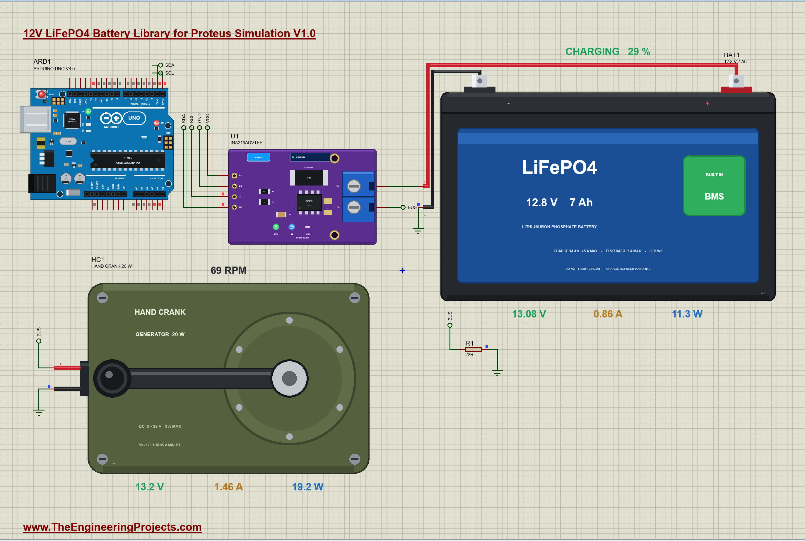
At 4.3 s the demo asks the hand for 90 turns a minute. The hand reaches its limit at 69 turns a minute, where the generator gives 13.17 V at 1.46 A, 19.2 W, for 50.2 W of work from the hand. The lamp takes its share of that current and the battery gets the rest: 0.86 A in at 13.08 V, 11.3 W, at 5.2 s. The charge has risen to 29 %, each cell is at 3.27 V, and the banner says about 5 h 45 min to full. Look at the curve: the dot has climbed onto the flat part, and from here to 90 % the voltage will gain only about three tenths of a volt.
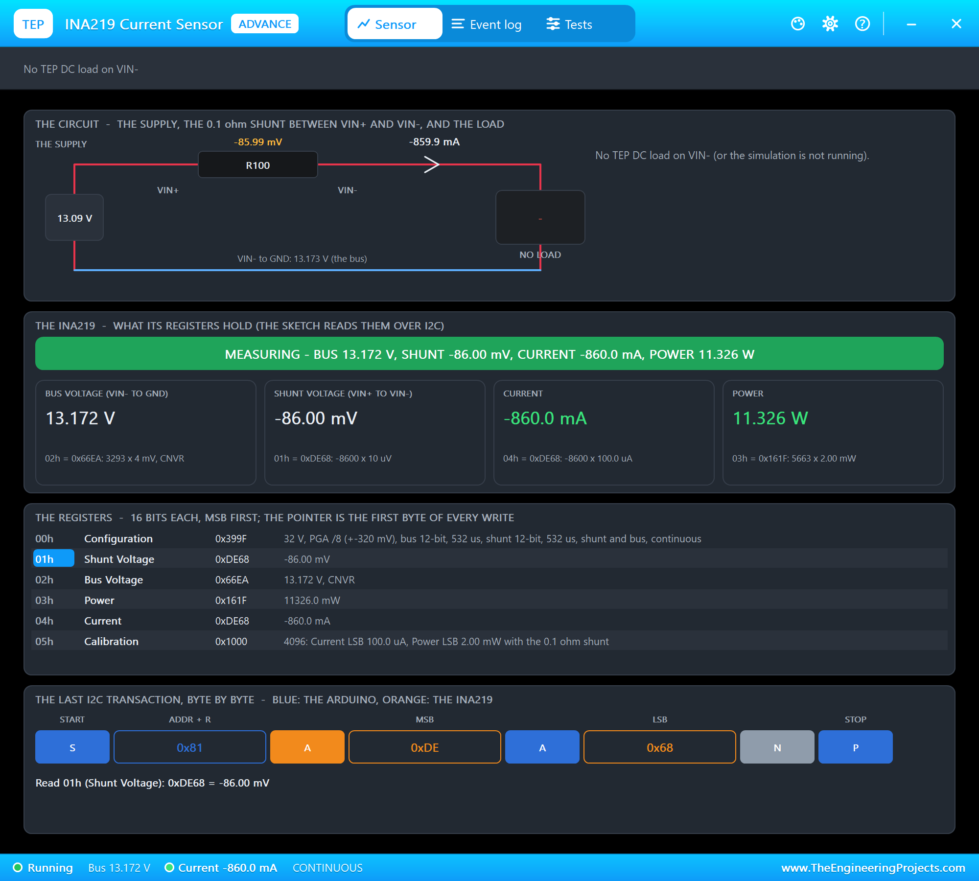
The INA219 measures the same current with its sign. Its pop-up shows 13.172 V on the bus, -86.00 mV across the shunt and -860.0 mA: negative, because the current flows from the bus into the battery, against the direction of a load current. Its Power register still shows a positive 11.326 W; the INA219 does not sign its power. The pop-up of the hand crank generator, taken at the same moment, shows the other end of the same wire.
Half Full, Then the Hand Lets Go
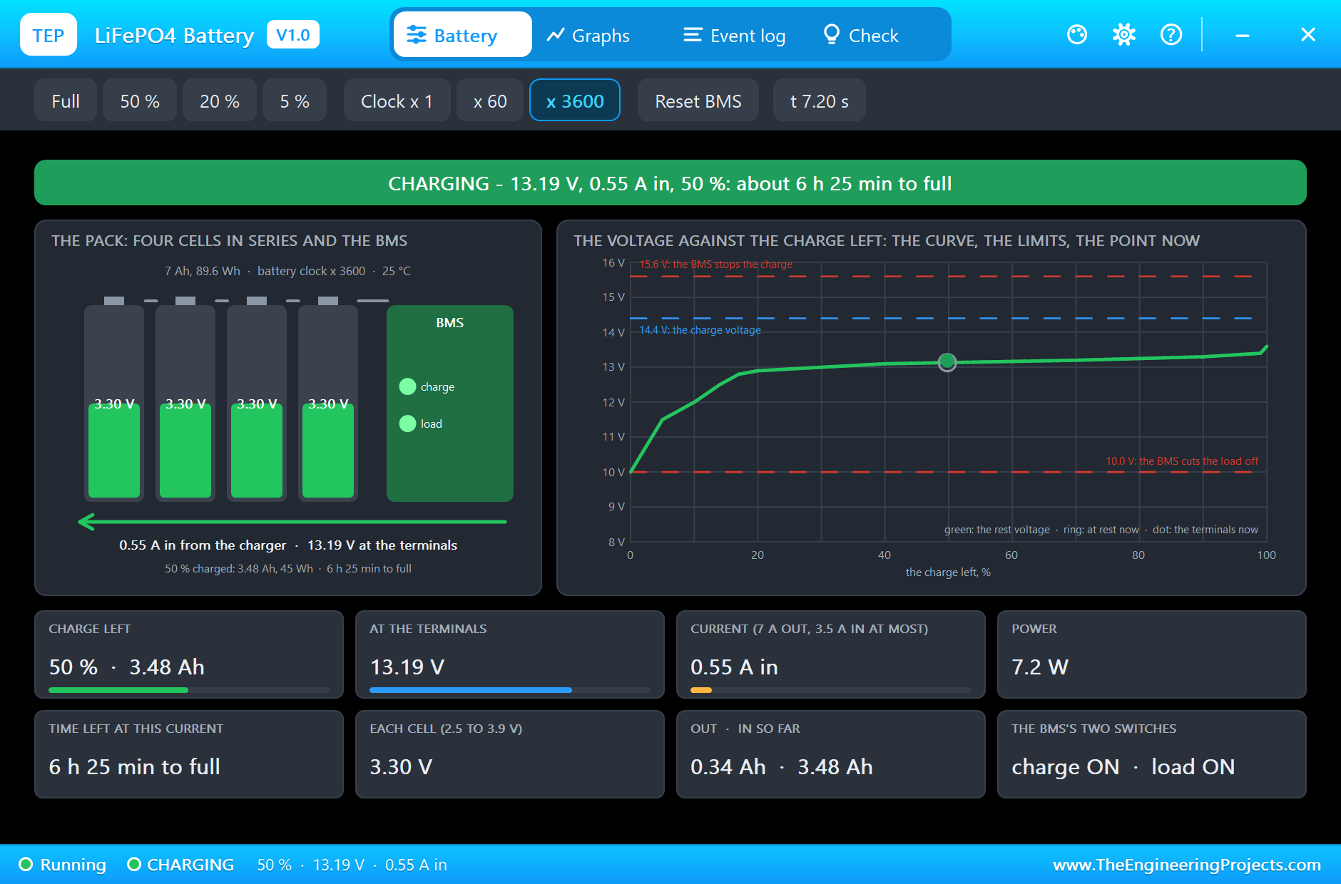
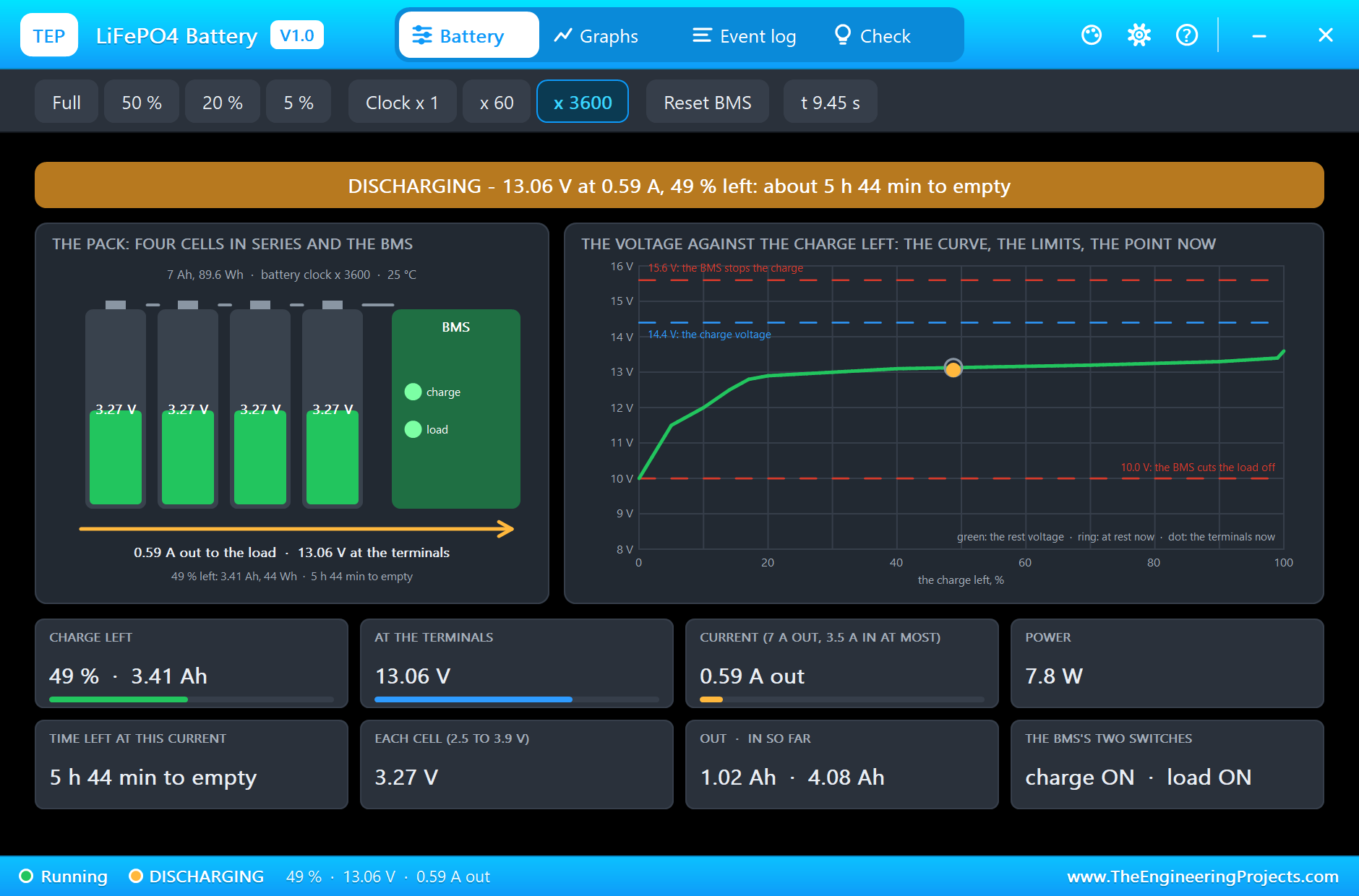
At 6.3 s the hand eases off to 60 turns a minute, and the charge current falls to 0.55 A at 13.19 V. The Event log marks 25 % charged at 4.884 s and 50 % at 7.251 s. At 8.3 s the hand lets go, with 56 % in the battery. Nothing dramatic happens on the bus: the battery simply takes over the lamp, and the current through the INA219 changes its sign. At 9.45 s the battery gives 0.59 A at 13.06 V, 7.8 W, with 49 % left, 3.41 Ah, enough for about 5 h 44 min of light. Compare the voltages: 13.08 V while charging at 29 % and 13.06 V while discharging at 49 %. A voltmeter could not tell these two states apart, and it would certainly not tell you the charge.
A Full Battery and a Charger Without a Limit
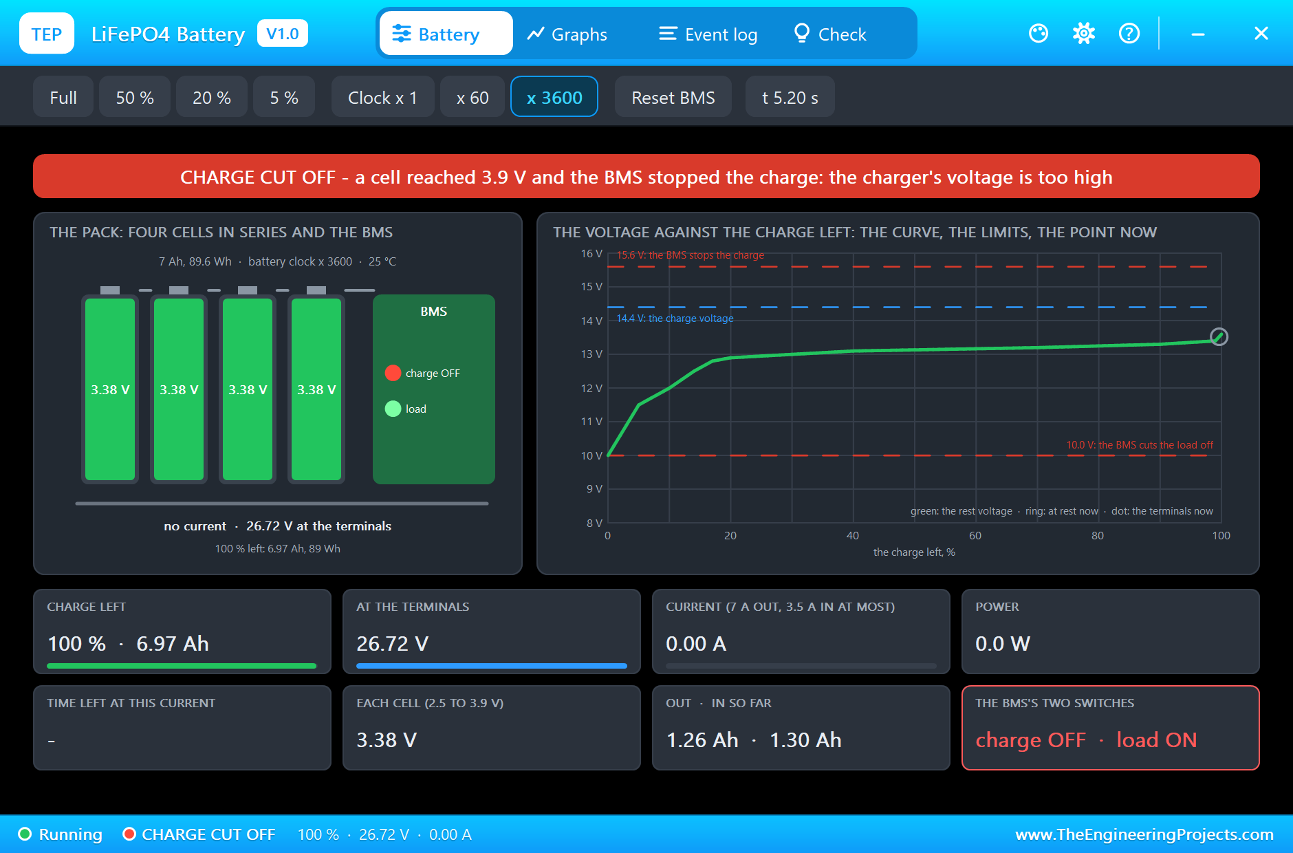
The demo never fills the battery, so we made a second simulation run with one change: SOC set to 99. The hand crank is a charger without a voltage limit, and this is what such a charger does to a full LiFePO4 battery. Over the last percent the cells take the current less and less willingly, the voltage at the terminals climbs fast, and at 4.737 s a cell reaches 3.91 V. The BMS stops the charge: CHARGE CUT OFF. In the pop-up the charge switch is red and the load switch is still green; the cells rest at 3.38 V each. The bus is now fed by the crank alone, and with nothing but the lamp on it the bus stands at 26.72 V, far more than a 12 V lamp should see and just over the 26 V that the INA219's bus pin may take. That is the reason why a charge controller belongs between a generator and a battery. When the hand lets go, the battery feeds the lamp again, because the block is one-way, and at 10.312 s the BMS allows a charge again.
The Graphs, the Event Log and the Check Page
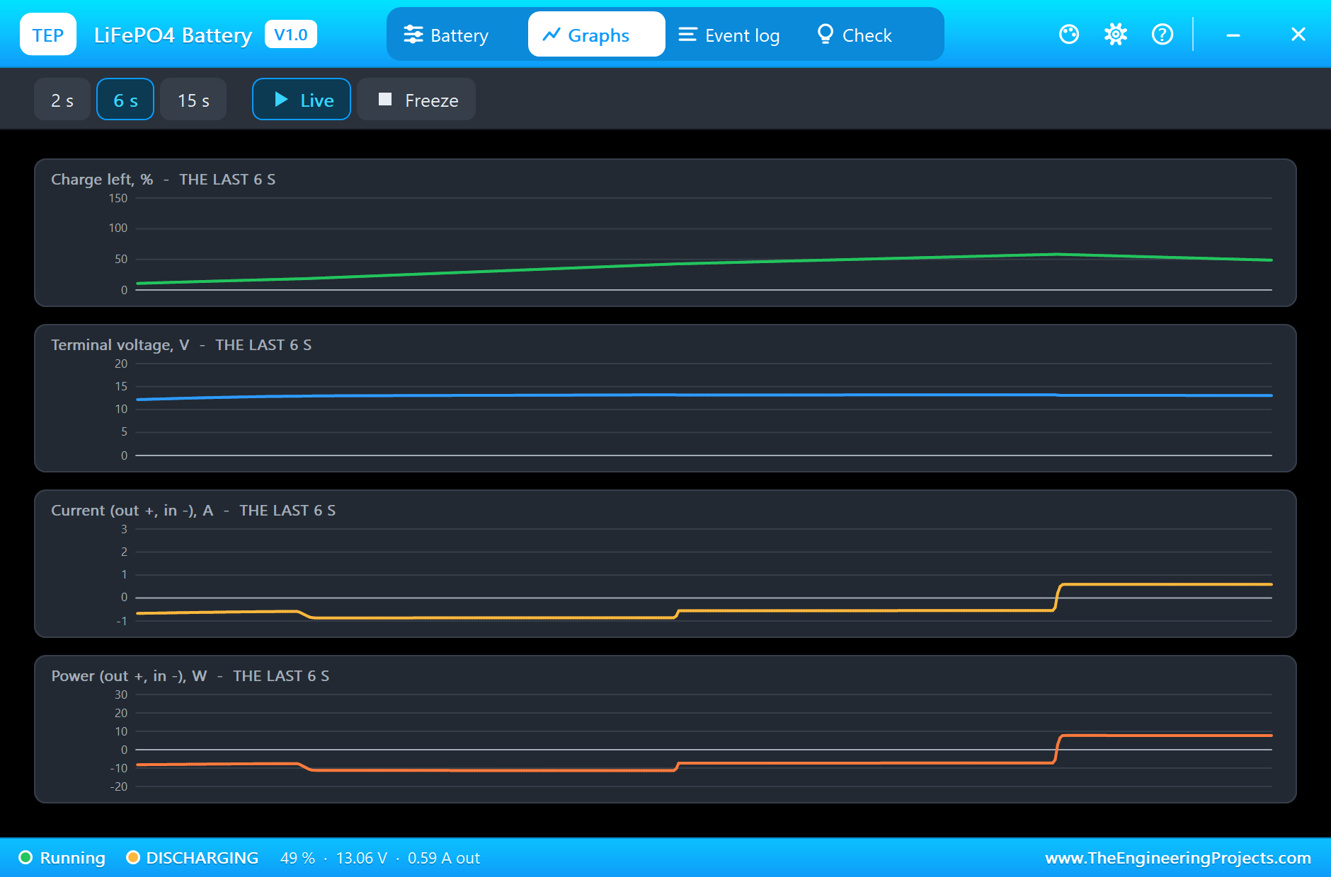
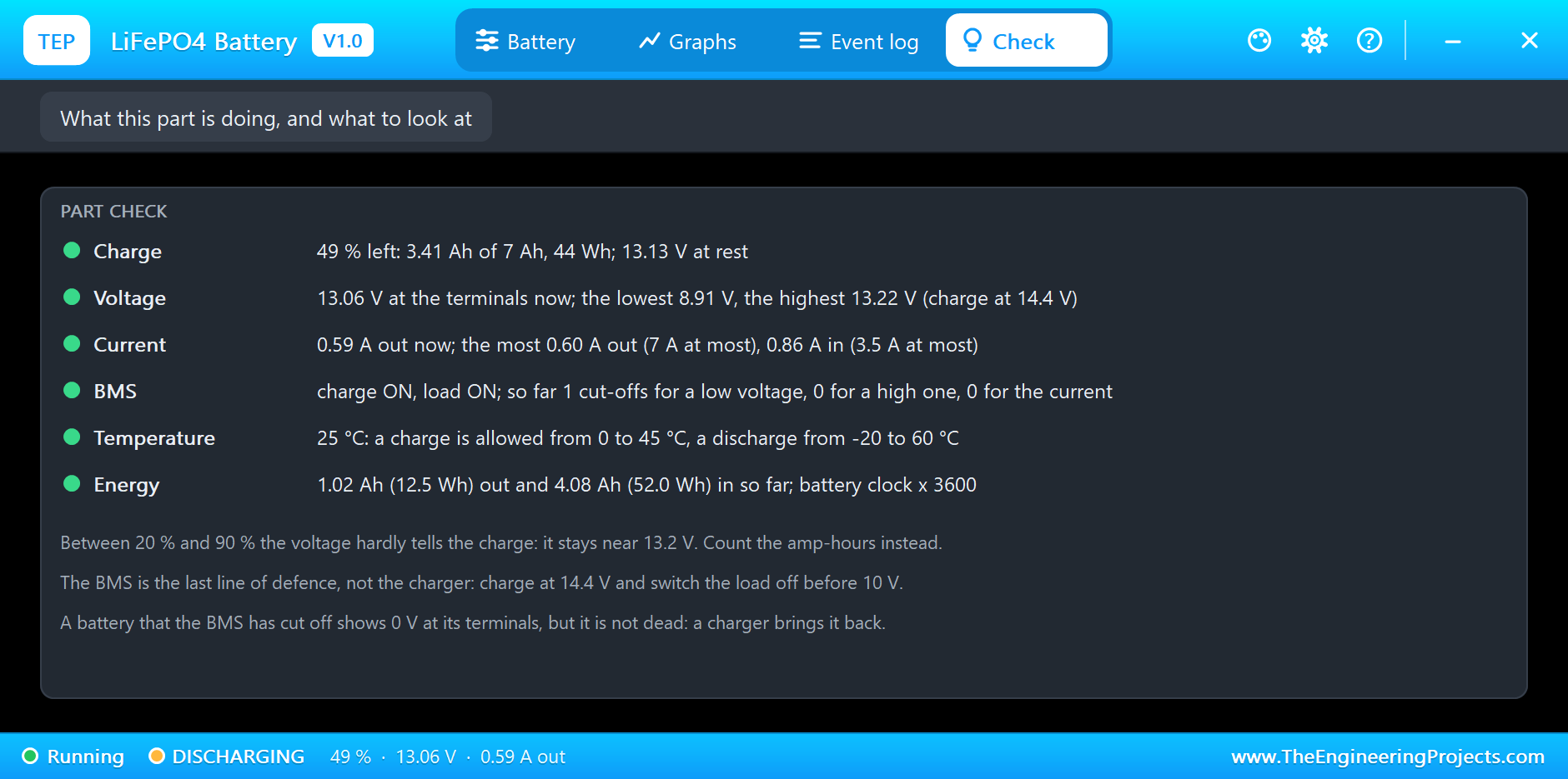
The Graphs page plots the charge left, the voltage at the terminals, the current and the power over the last 2, 6 or 15 simulated seconds; a charge shows as a negative current and a negative power. The Event log keeps the cut-off, the moment the BMS closed again, every change between charging, discharging and resting with the time left, and a mark at every quarter of the charge. The Check page sums up the run: 1.02 Ah (12.5 Wh) out and 4.08 Ah (52.0 Wh) in, one cut-off for a low voltage, 8.91 V as the lowest voltage at the terminals and 13.22 V as the highest.
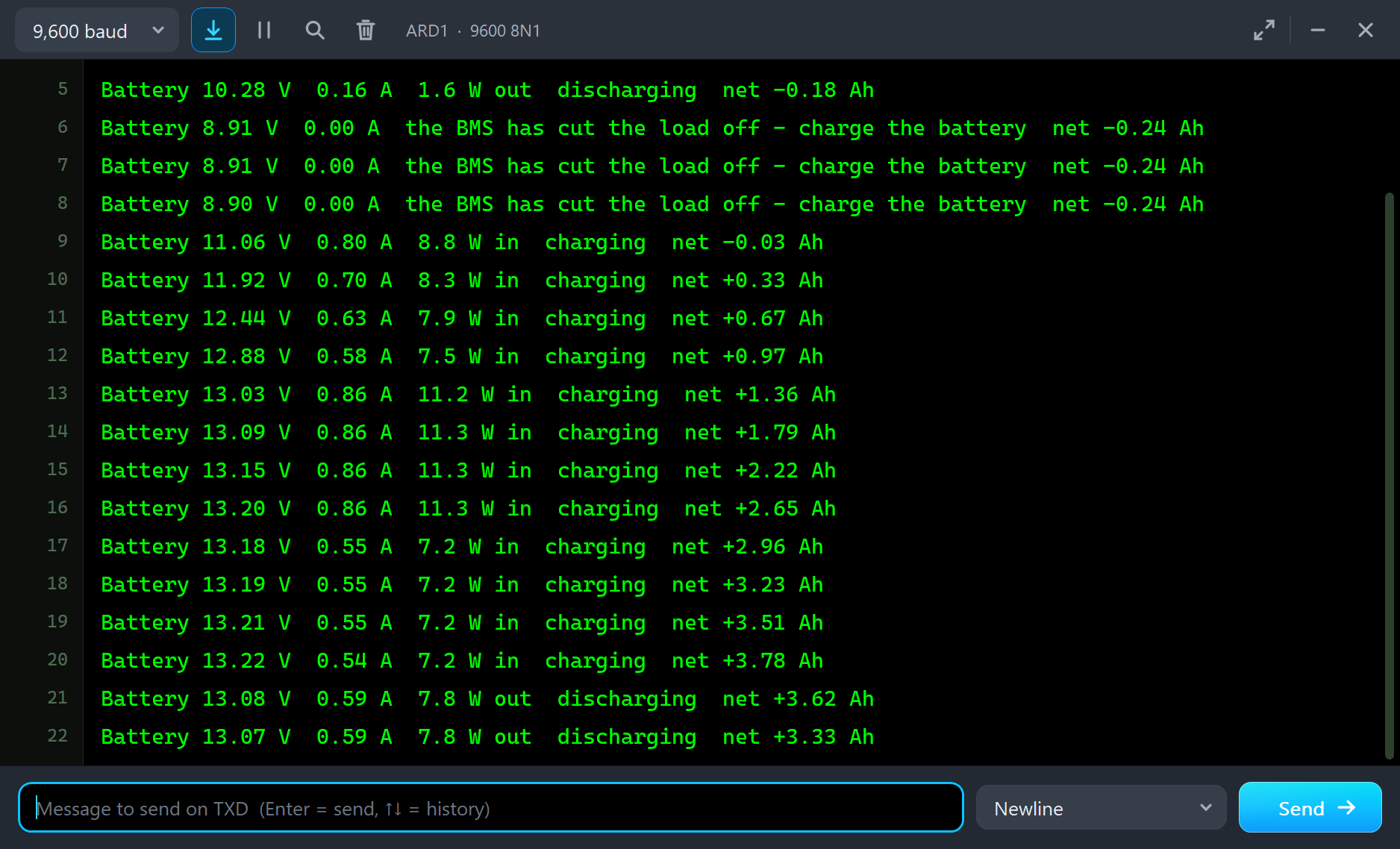
The monitor tells the same story from the Arduino's side. Its counter stands at -0.24 Ah when the BMS cuts the load off and at +3.33 Ah on the last line, close to the battery's own count. The small difference comes from the first quarter of a second, when the UNO was still starting and the battery was already working.
Try It Yourself
- Set SOC to 99 and run the demo again: the crank fills the battery and the BMS stops the charge at 3.9 V a cell, as in our second run.
- Click 5 % while the crank is at rest and watch the cut-off again; then click 60 in the crank's pop-up to bring the battery back.
- Change R1 to 0.47 ohm: more than 20 A flows for a moment and the BMS opens for over-current. It closes again when the load is gone.
- Set TEMP to -5 and run again: the battery feeds the lamp, but the BMS refuses every charge.
- Click Clock x 1 to see the battery in real time: a 7 Ah battery hardly moves in ten seconds.
Ideas to Extend the Demo
- Let the sketch switch the load off itself at 20 %, long before the BMS has to.
- Show the amp-hours and the state on an LCD, as a real battery monitor does.
- Replace the hand crank by a solar panel and a charge controller and build a small solar system.
Your Own Sketches
The demo sketch is in the zip file, and you can change it in the Arduino IDE. New to Arduino? Start with our Arduino Tutorial for Beginners. Export the compiled binary, and set the UNO's PROGRAM property to the new file. Our guide on How to get the HEX file from Arduino shows you where the file ends up.
Things to Know Before Using a Real LiFePO4 Battery
- Use the right charger: 14.4 V (14.2 to 14.6 V) with a current limit; 1.4 A is kind to a 7 Ah pack and 3.5 A is its limit. A lead-acid charger with a desulphation mode is not suitable.
- Do not lean on the BMS: it is there for the day something goes wrong. End the charge and the discharge yourself.
- 0 V does not mean dead: a battery that the BMS has cut off wakes up on a charger. Do not leave it empty for weeks, though.
- Never charge below 0 °C: a good BMS refuses, a cheap one may not.
- Fuse the + lead: a real pack can give far more than 20 A for a moment, and a short circuit is dangerous.
Troubleshooting
- 0 V at the terminals, BMS CUT OFF: the pack fell to 10.0 V. Charge it; the BMS closes again at 12.0 V.
- CHARGE CUT OFF: a cell reached 3.9 V; the charger's voltage is too high or it has no voltage limit. Use 14.4 V.
- BMS: OVER CURRENT: more than 20 A flowed. Remove the load, or click Reset BMS in the pop-up.
- The charge hardly moves: at SPEED 1 a 7 Ah battery needs hours, as a real one does. Raise SPEED to 60 or 3600.
- The voltage stays at 13.2 V whatever the charge: that is LiFePO4. Read the charge in the pop-up, or count the amp-hours.
- It will not charge: TEMP is below 0 °C or above 45 °C.
- The part is not simulated:
TEPLIFEPO4.DLLis missing from MODELS and from the project folder.
Limitations of the Simulation
- The rest voltage follows the sellers' charts with straight lines between twelve points; the capacity, the charge and discharge limits and the two cut-off voltages are from a maker's sheet of a 12.8 V 7 Ah pack.
- Our own figures: the 80 milliohm and its rise when the battery is empty or cold, the slow polarisation, the shape of the charge taper, the voltages at which the BMS closes again, its delays and the 20 A and 60 A levels.
- Not modelled: ageing and cycle life, cells that drift apart (all four are equal), the heat the pack makes, the BMS's own supply current and damage from a deep discharge.
- Arduino is a name of Arduino; this library is not made or endorsed by Arduino, Labcenter or any battery maker.
- Tested in Proteus 8.5 in November 2026 (the demo as shipped). Proteus 7 is not supported.
So, that was all about the 12V LiFePO4 Battery Library for Proteus Simulation. I hope it helps you try a battery project in a simulation before you connect a real pack: a voltage that stays flat while the charge goes down, a counter that knows the charge anyway, and a BMS that cuts off, waits for a charger and closes again. If you have any questions, ask in the comments and I will help you out. Till the next tutorial, take care and have fun!

Comments
0