


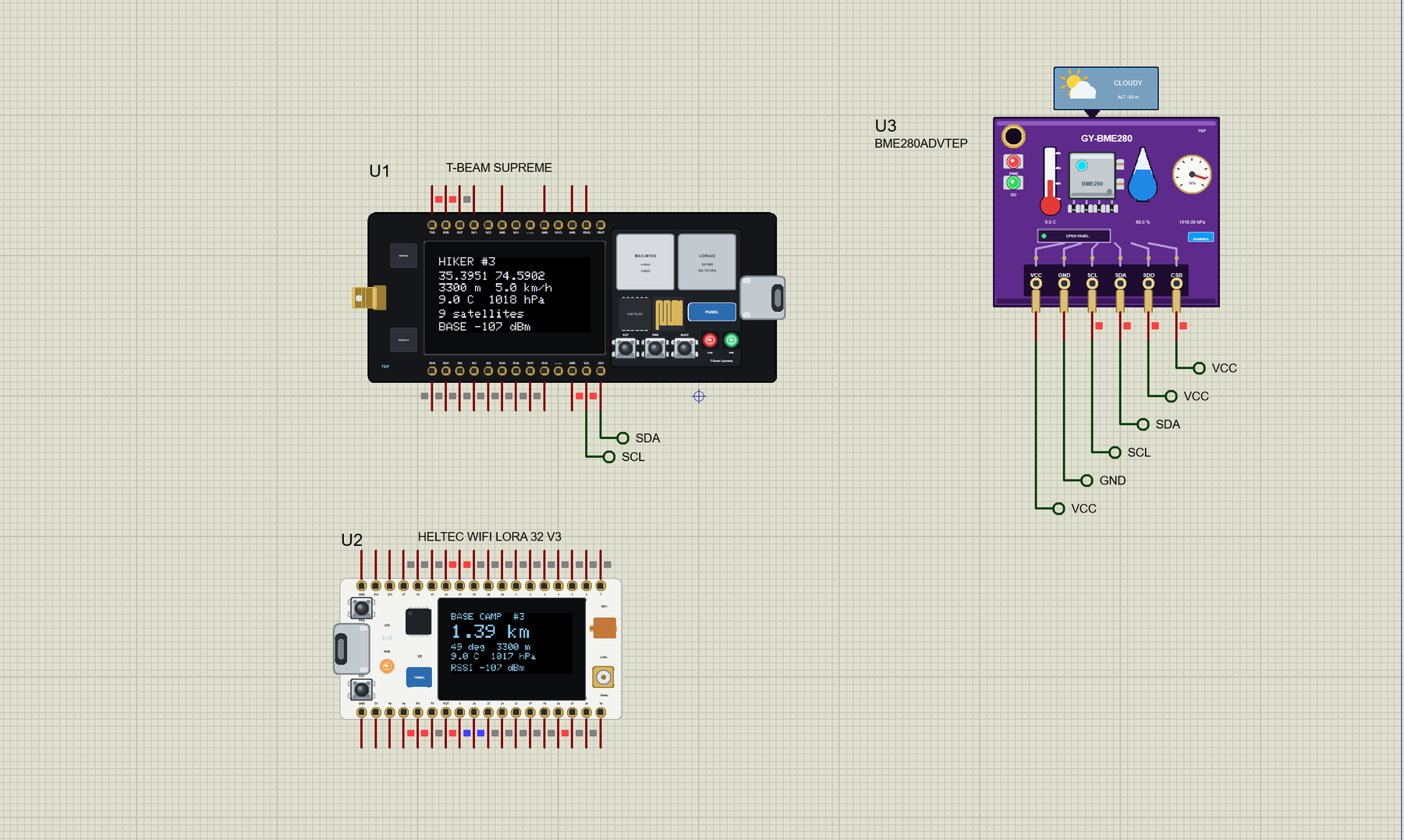
T-Beam Supreme Library for Proteus: ESP32-S3 LoRa GPS Tracker


Hello friends, I hope you all are doing great. Today, I am going to share the LilyGO T-Beam Supreme Library for Proteus. The T-Beam Supreme is a long black board with an ESP32-S3, an SX1262 LoRa radio, a GPS receiver and a bright 1.3 inch OLED, all on one board. It is the favourite of people who build off-grid mesh radios and trackers, because it can tell a friend where you are from kilometres away, with no phone network at all. With this library it runs your ESP32-S3 Arduino sketch in Proteus 8.5, with the radio, the GPS and the OLED working on the part.
T-Beam Supreme Library for Proteus
Latest version: V1.0 (November 2026, this tutorial)
Helping Tools
- Laptop WiFi Monitor: a laptop on the Wi-Fi of your design: a browser, a TCP / UDP terminal and ping
- Mobile WiFi Monitor: a smartphone that opens the pages of your board and sends it commands
- Serial Monitor Advance: a serial terminal window for the UART of your board
For the demo we built an off-grid hiker tracker. A hiker walks up a mountain with a T-Beam Supreme. Every five seconds it sends its position by LoRa to a Heltec V3 at the base camp, which works out how far away the hiker is and in which direction. A BME280 watches the air pressure and warns of a storm, and the BOOT button sends an SOS.
NOTICE: Proteus has no ESP32-S3 or SX1262 model, so our team has put a lot of effort into building this board ourselves: the T-Beam Supreme's pins, LEDs, radio, GPS, OLED and Wi-Fi are all our own model, and your sketch compiles with our free TEP Boards for Proteus add-on. Your feedback is the fuel that keeps us going, so please tell us what you think in the comments below or in the LilyGO T-Beam Supreme board of our forum. And if our free libraries help you, you can buy us a coffee. So, let's get started with the LilyGO T-Beam Supreme Library for Proteus:
What is the LilyGO T-Beam Supreme?
The T-Beam Supreme is the newer, stronger brother of the classic T-Beam. Its heart is a small plug-in board called the T-Beam-S3 Core, with an ESP32-S3, 8 MB of flash, 8 MB of PSRAM, an SX1262 LoRa radio and a GNSS module, either the u-blox MAX-M10S or the Quectel L76K. The main board adds a 1.3 inch 128 x 64 SH1106 OLED, an AXP2101 power chip with a holder for an 18650 cell on the back, a BME280 weather sensor, a QMC6310 compass, a QMI8658 motion sensor, a real-time clock and a TF card socket. An SMA socket carries the LoRa antenna.
| T-Beam Supreme | T-Beam V1.2 | Heltec V3 | |
|---|---|---|---|
| Processor | ESP32-S3 | ESP32 | ESP32-S3 |
| GPS | on the board | on the board | none |
| OLED | 1.3 inch SH1106 | 0.96 inch SSD1306 | 0.96 inch SSD1306 |
| Battery | 18650 holder | 18650 holder | small LiPo socket |
| Sensors | BME280, compass, IMU | none | none |
Why LoRa for a Hiker?
A phone needs a tower, and in the high valleys there may be none for a day's walk. LoRa trades speed for reach: it sends only a few hundred bits a second, but a small radio with a good antenna can cover several kilometres on a mountainside, on a tiny amount of power, on licence-free bands such as 868 MHz. A position and a few numbers fit in one short packet, so that slow speed does not matter at all. That is why open projects such as Meshtastic run on this very board. If you know our LilyGO T-Beam Library for Proteus, this is the same idea with a faster processor and a bigger screen.
Features of the T-Beam Supreme Library for Proteus
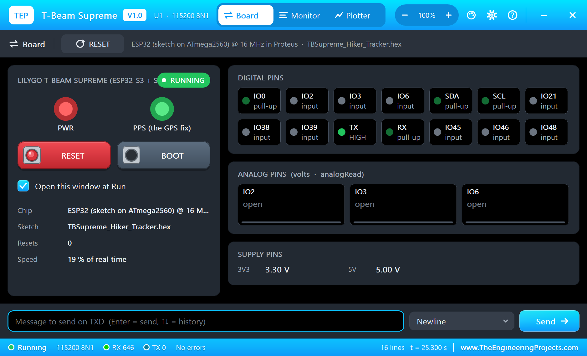
- The board as it looks: the black T-Beam Supreme with the SMA socket, the OLED between the two rows of pads, the T-Beam-S3 Core with its GNSS module, LoRa can, ESP32-S3 and antenna, the RST, PWR and BOOT buttons, the CHG and PPS LEDs and USB-C.
- Your sketch: a .hex for "T-Beam Supreme (TEP Proteus)" with the board's GPIO numbers - analogRead 0 to 4095, analogWrite and ledc PWM, attachInterrupt, Serial, Wire and SPI.
- The SX1262 on the board: RadioLib with
new Module(10, 1, 5, 4)talks to the other TEP LoRa boards of the design, with RSSI and SNR. - The GPS on the board: NMEA at 9600 baud on Serial1, ready for TinyGPSPlus, from properties for the position, height, speed, heading and satellites.
- The OLED on the board: a real SH1106 with 132 columns of memory at I2C 0x3C. What your sketch draws appears on the part.
- A complete package: about 3.7 MB with the board, the add-on, the Heltec V3 and BME280 libraries and the demo, without the source code of the models.
The T-Beam Supreme in Proteus
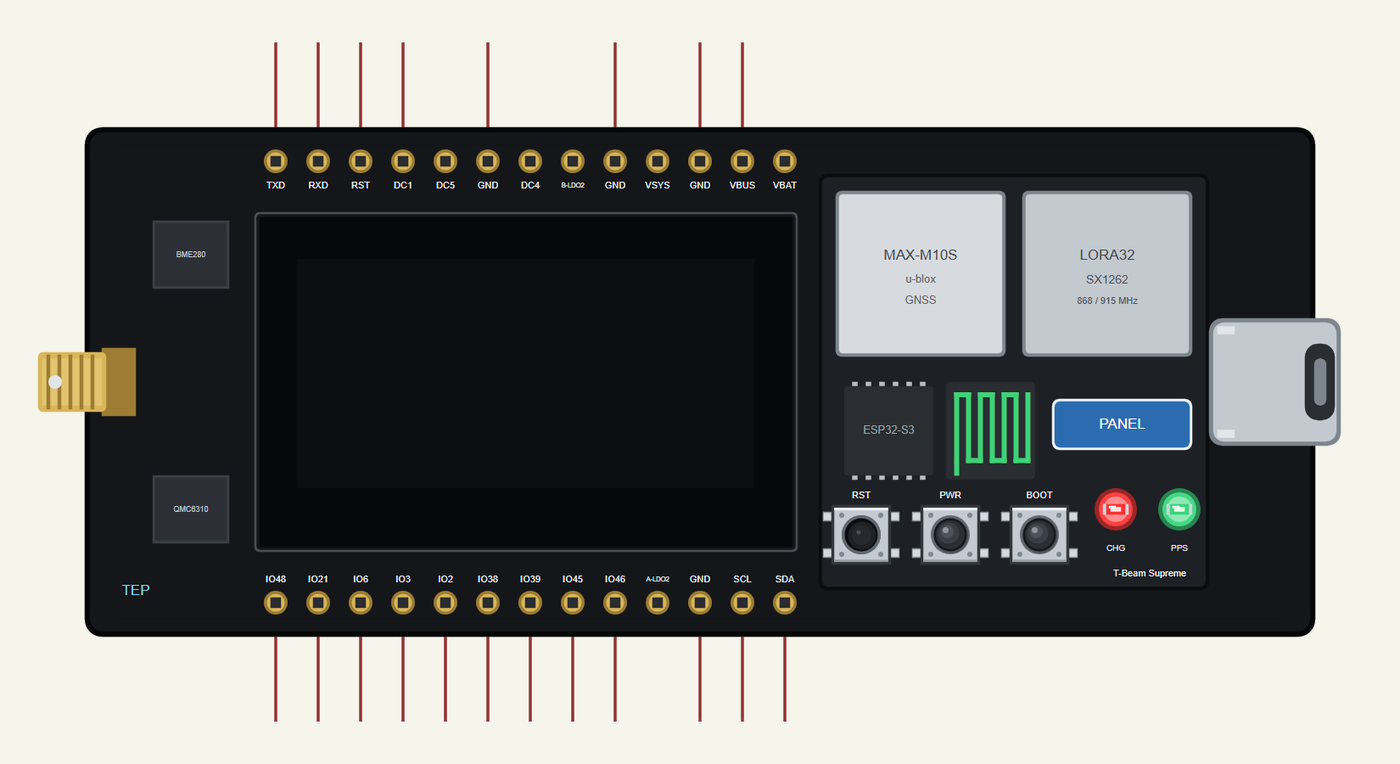
Search T-BEAM SUPREME in Pick Devices; the device is in TEPTBSUPREME.LIB (Microprocessor ICs, ESP32 Boards), with the prefix U. The board lies in landscape, with the SMA socket on the left. It has two windows: click the USB-C port for the serial monitor, and the PANEL pad or the OLED for the board's panel. The 13 + 13 pads come from LilyGO's pin diagram, turned with the board. We drew it at about two thirds of its real size, so that it fits an A4 sheet with room for other parts.
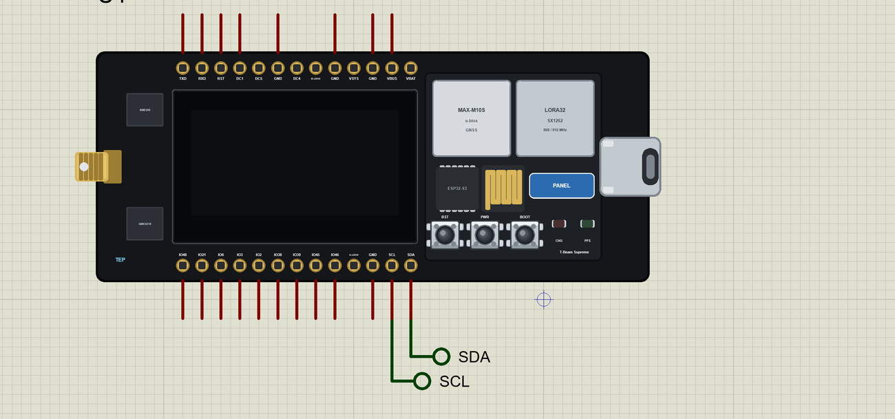
The Pins
| Pins | GPIO | What the library does with them |
|---|---|---|
| SDA / SCL | 17 / 18 | Wire, with the OLED at 0x3C on the same bus |
| TXD / RXD | 43 / 44 | Serial, the board's monitor |
| IO2, IO3, IO6 | 2, 3, 6 | GPIO, PWM, interrupt, analogRead |
| IO21, IO38, IO39 | 21, 38, 39 | GPIO, PWM, interrupt |
| IO45, IO46, IO48 | 45, 46, 48 | GPIO, PWM, interrupt |
| DC1, VBUS, GND | - | 3.3 V, 5 V, ground |
The radio and the GPS have no pads of their own, because they sit on the board: the SX1262 on GPIO10, 12, 11, 13, 5, 4 and 1, the GPS on GPIO9 and 8, and BOOT on GPIO0. The variant gives them LilyGO's names, such as RADIO_CS_PIN and GPS_RX_PIN, so a sketch reads just like LilyGO's examples. The other rails are drawn only.
Download LilyGO T-Beam Supreme Library for Proteus
Click the button below to download LilyGO-T-Beam-Supreme-Library-for-Proteus-v1.0.zip (about 3.7 MB, without the source code of the models):
LilyGO T-Beam Supreme Library for Proteus V1.0- README.txt: installation, the demo, the pins, the properties, troubleshooting and the limits.
- Proteus Library Files:
TEPTBSUPREME.LIBand the demo's parts:TEPHELTECV3.LIBandTEPBME280.LIB. - Proteus Model Files:
TEPNET.DLL(the boards, their radios, the GPS and the OLEDs) andTEPBME280.DLL. - Arduino Code: the two demo sketches and the TEP Boards for Proteus add-on 1.48.0.
- Proteus Simulation: the demo project, its two HEX files and copies of the DLLs.
No Proteus yet? Read How to Download and Install Proteus 7 and 8. New to libraries? Follow How to Install a New Library in Proteus.
How to Install LilyGO T-Beam Supreme Library for Proteus
- Close Proteus and extract the whole zip file, for example to your Desktop.
- Copy the files from Proteus Library Files into the LIBRARY folder of Proteus.
- Copy the DLLs from Proteus Model Files into the MODELS folder, replacing an older TEPNET.DLL.
- Delete
TEPTBSUPREME.IDXfrom the LIBRARY folder if it is there. - For your own sketches, copy Arduino Code\TEP Boards for Proteus\hardware into your Arduino sketchbook (Documents\Arduino) and restart the Arduino IDE; the board is T-Beam Supreme (TEP Proteus). Install RadioLib, TinyGPSPlus, Adafruit BME280 and Adafruit GFX from the Library Manager.
- Start Proteus, press P and search for T-BEAM SUPREME.
Demo: an Off-Grid Hiker Tracker
Picture a group trekking above Fairy Meadows in the north of Pakistan. The last phone signal was far down the valley. One person stays at the base camp, and the others walk on with a small tracker in a backpack. The camp wants to know three things: where are they, is the weather turning, and is anyone in trouble?
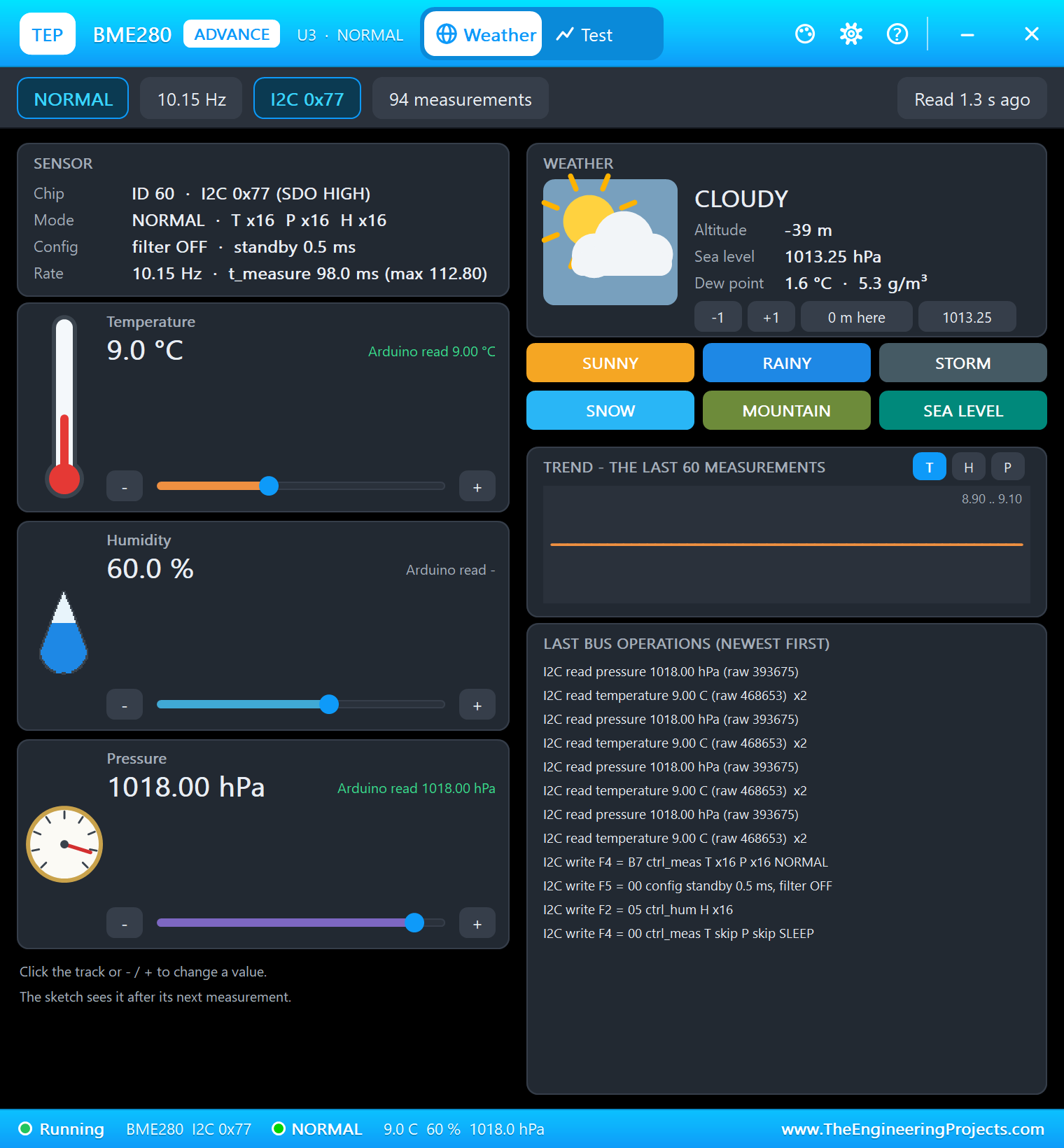
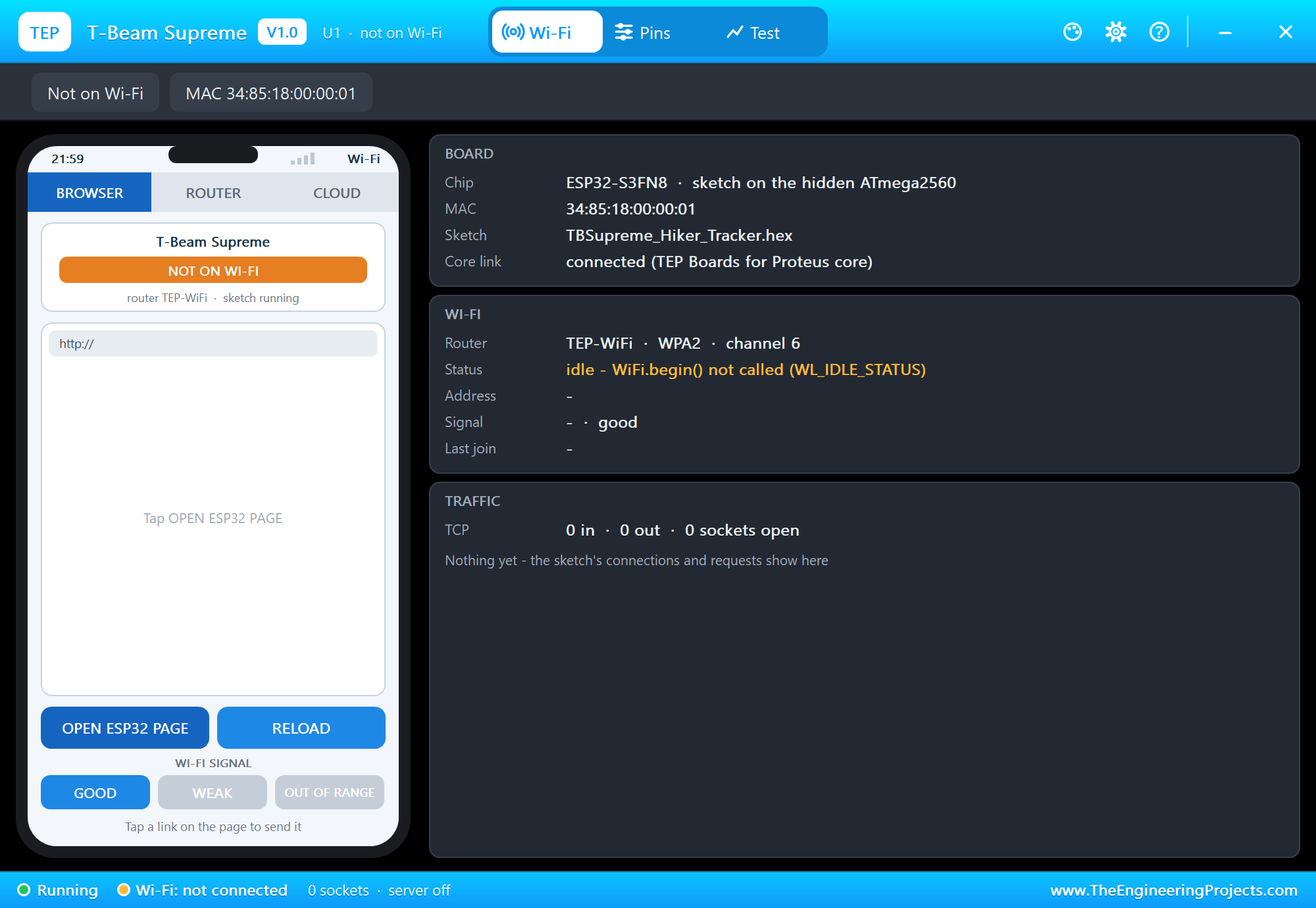
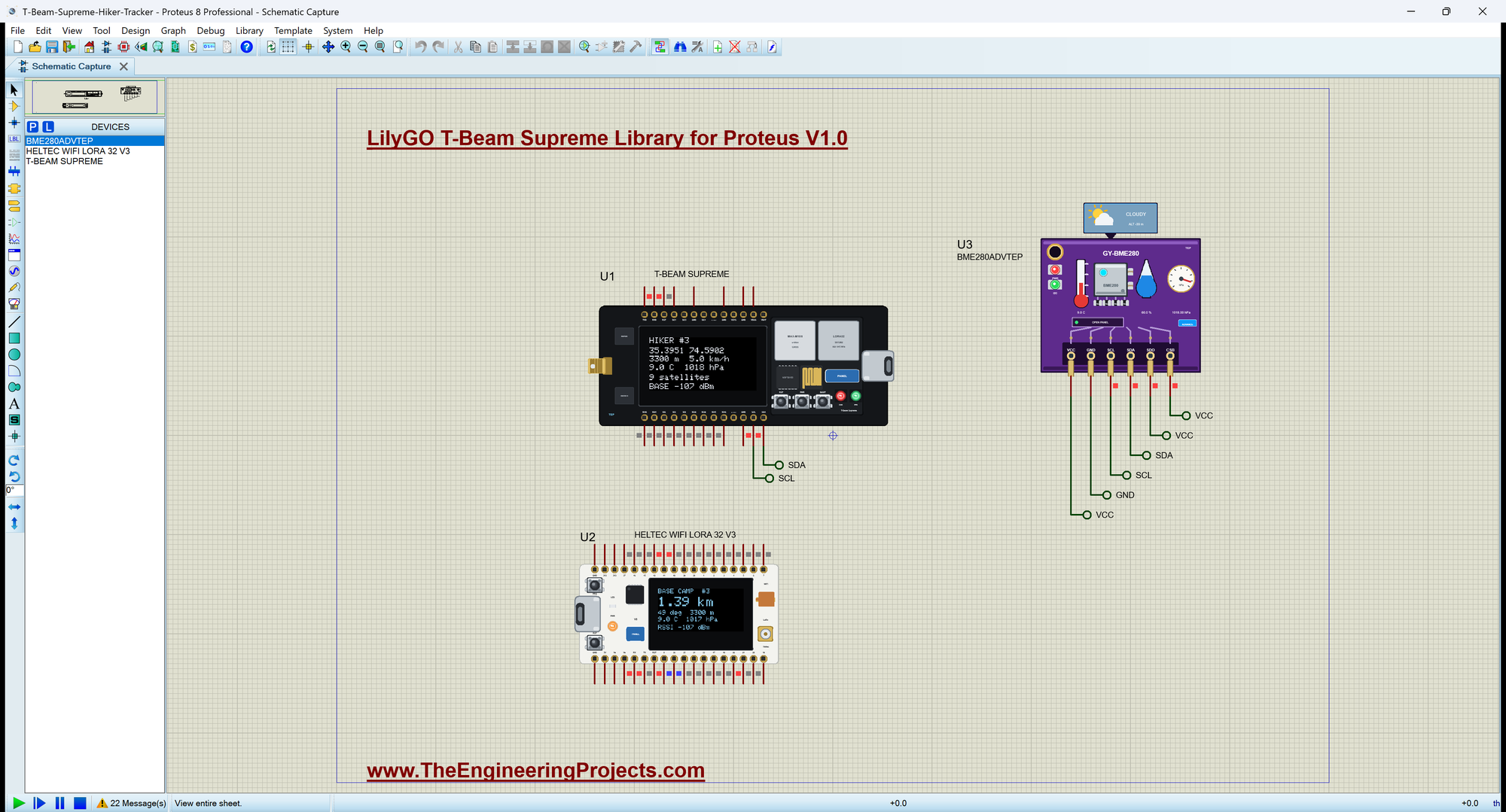
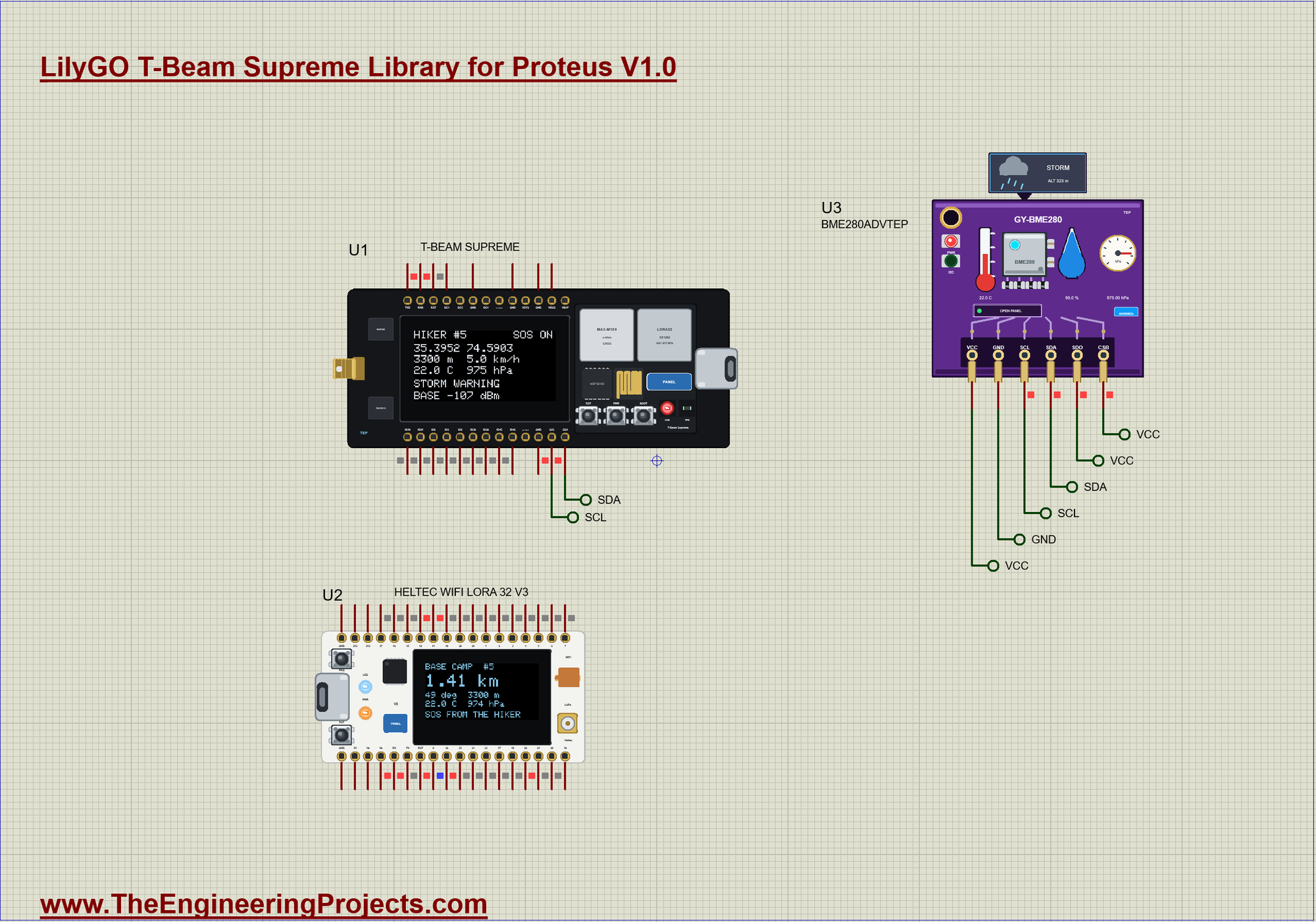
Open T-Beam-Supreme-Hiker-Tracker.pdsprj. U1 runs TBSupreme_Hiker_Tracker.hex, and its GPS walks north-east at 5 km/h. U2 is the board from our Heltec WiFi LoRa 32 V3 Library for Proteus, running Heltec_Base_Camp.hex. U3 is the sensor from our BME280 Sensor Library for Proteus in the Advance version. A real T-Beam Supreme has a BME280 on the board, but our model does not include that one, so U3 stands in for it on the same I2C bus at the same address, 0x77. Your sketch stays the same on both.
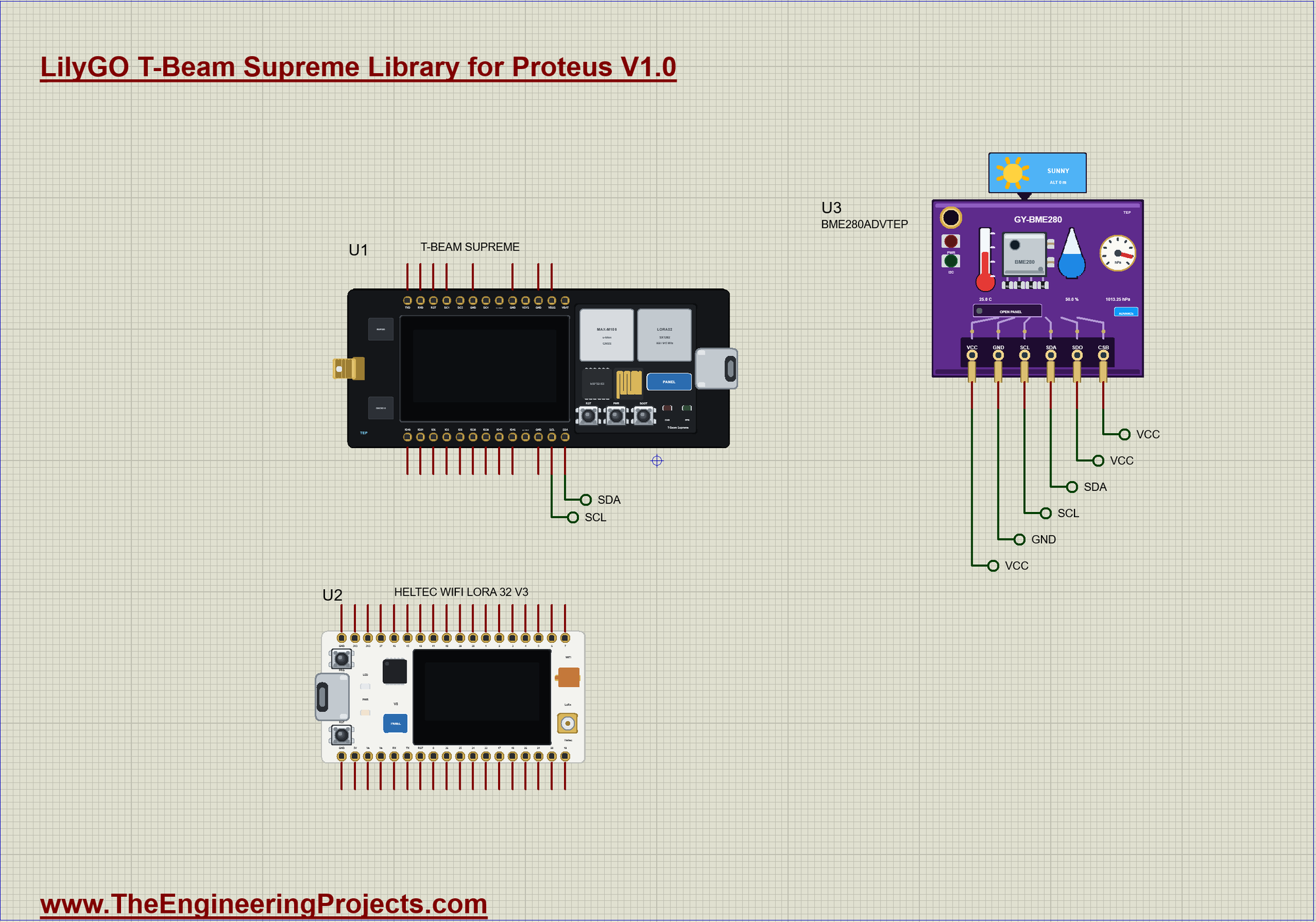
| Module pin | Net label | Board pin | What it does |
|---|---|---|---|
| BME280 SDA, SCL | SDA, SCL | 17, 18 | I2C |
| BME280 SDO | VCC | - | selects address 0x77 |
| BME280 CSB | VCC | - | selects I2C |
| BME280 VCC, GND | VCC, GND | - | the supply |
A Driver for the SH1106
The OLED on this board is an SH1106, not the common SSD1306, and that catches many people out. It looks the same, but it has 132 columns of memory for its 128 pixels, and it has no horizontal mode that would take the whole screen in one long write. Send it SSD1306 data and you get a shifted, garbled picture. So we wrote a very small driver. It inherits from Adafruit_GFX, which gives us text and lines, and all we have to supply is drawPixel() and a way to send the screen. Each page is eight pixels high, and the column starts at 2 because that is where the glass begins:
    for (byte page = 0; page < 8; page++) {
      command(0xB0 | page);
      command(0x02);                                        // column 2: the SH1106 has 132 columns and the glass starts at 2
      command(0x10);
      for (byte x = 0; x < 128; x += 16) {
        Wire.beginTransmission(0x3C);
        Wire.write(0x40);
        Wire.write(ram[page] + x, 16);
        Wire.endTransmission();
      }
    }
Reading the GPS
The GPS speaks NMEA at 9600 baud on Serial1. TinyGPSPlus takes those sentences one character at a time, so the sketch simply feeds it everything that has arrived on each pass through loop(). The height comes in a different sentence from the position, which is why the first report waits for both before it prints the fix.
The Radio
RadioLib drives the SX1262. The module takes four pins: chip select, DIO1, reset and BUSY. All the settings must match on both boards: here 868 MHz, 125 kHz of bandwidth, spreading factor 7 and coding rate 4/5. Use 915 MHz in the Americas. A higher spreading factor reaches further but takes longer in the air:
void send(const __FlashStringHelper *why) {
  ++seq;
  const bool ok = gps.location.isValid();
  char packet[64];
  snprintf(packet, sizeof packet, "H,%u,%ld,%ld,%d,%d,%d,%d,%d", seq, ok ? lround(gps.location.lat() * 100000.0) : 0L, ok ? lround(gps.location.lng() * 100000.0) : 0L,
           (int)gps.altitude.meters(), (int)(tempC * 10), (int)hpa, storm ? 1 : 0, sos ? 1 : 0);
  Serial.print(F("TX #")); Serial.print(seq); Serial.print(F(" (")); Serial.print(why); Serial.print(F("): ")); Serial.println(packet);
  const int state = radio.transmit(packet);
  radioFlag = false;                                        // the TxDone edge is not a packet
  if (state != RADIOLIB_ERR_NONE) { Serial.print(F("transmit failed, code ")); Serial.println(state); }
  radio.startReceive();
  lastSend = millis();
  show();
}
The packet is plain text, such as H,3,3539514,7459017,3300,90,1017,0,0: the sequence number, the position in units of 0.00001 degree, the height, the temperature in tenths, the pressure, and the storm and SOS flags. Text costs a few more bytes, but you can read it in the monitor. Long integers keep the position exact, since a float has only about seven digits.
The Storm Warning
Air pressure falls before bad weather, and a fall of several hectopascals in a few hours is a clear warning in the mountains. The sketch keeps the first reading and compares each new one with it. A real tracker should compare with the reading from three hours ago, and take care, because a hiker who climbs also sees the pressure fall. The height from the GPS can correct for that:
void readAir() {
  if (millis() - lastAir < 2000) return;
  lastAir = millis();
  tempC = bme.readTemperature();
  hpa = bme.readPressure() / 100.0;
  if (firstHpa == 0) { firstHpa = hpa; return; }
  const bool now = firstHpa - hpa >= STORM_FALL;
  if (now != storm) {
    storm = now;
    Serial.print(storm ? F(">> STORM WARNING: ") : F(">> The weather is settling: ")); Serial.print(hpa, 1); Serial.println(F(" hPa"));
    send(F("weather"));
  }
}
Hearing the Answer
The base camp answers each packet with its sequence number, so the hiker knows the message got through. After every transmit the radio must go back to receiving, and the packet arrival raises DIO1, which sets a flag. The work is done in loop(), not in the interrupt:
void checkRadio() {
  if (!radioFlag) return;
  radioFlag = false;
  String text;
  const int state = radio.readData(text);
  if (state == RADIOLIB_ERR_NONE && text.startsWith("B,")) {
    ackRssi = radio.getRSSI();
    ++acks;
    heardSeq = text.substring(2).toInt();
    Serial.print(F("The base camp heard #")); Serial.print(text.substring(2)); Serial.print(F(", RSSI ")); Serial.print(ackRssi, 1); Serial.println(F(" dBm"));
    show();
  }
  radio.startReceive();
}
At the Base Camp
The Heltec V3 knows its own position, fixed in the sketch. For each packet it works out the distance and the direction on a flat map, which is close enough over a few kilometres: one unit of 0.00001 degree of latitude is about 1.11 m, and longitude shrinks by the cosine of the latitude. atan2() gives the bearing from the camp. Its OLED shows the result in big digits, and its white LED lights for an SOS.
Run the Demo
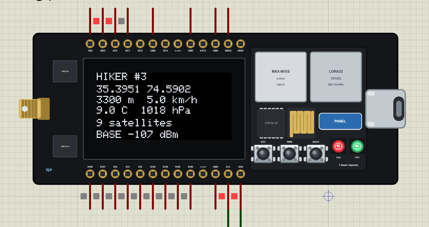
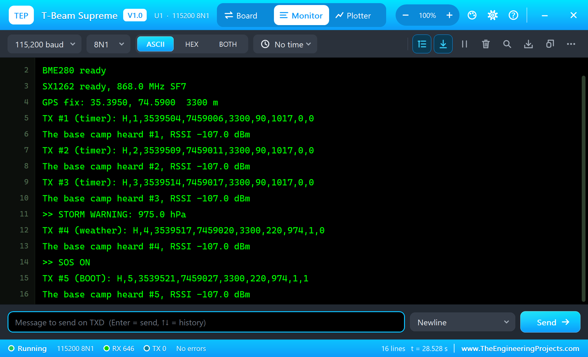
Press Run. The boards start, the GPS finds its fix after a few seconds, and the first packet goes out. The hiker's monitor, the same window as our TEP Serial Monitor Advance for Proteus, shows each packet and each answer:
T-Beam Supreme Hiker Tracker - The Engineering Projects
BME280 ready
SX1262 ready, 868.0 MHz SF7
GPS fix: 35.3950, 74.5900  3300 m
TX #1 (timer): H,1,3539504,7459006,3300,90,1017,0,0
The base camp heard #1, RSSI -107.0 dBm
TX #2 (timer): H,2,3539509,7459011,3300,90,1017,0,0
The base camp heard #2, RSSI -107.0 dBm
TX #3 (timer): H,3,3539514,7459017,3300,90,1017,0,0
The base camp heard #3, RSSI -107.0 dBm
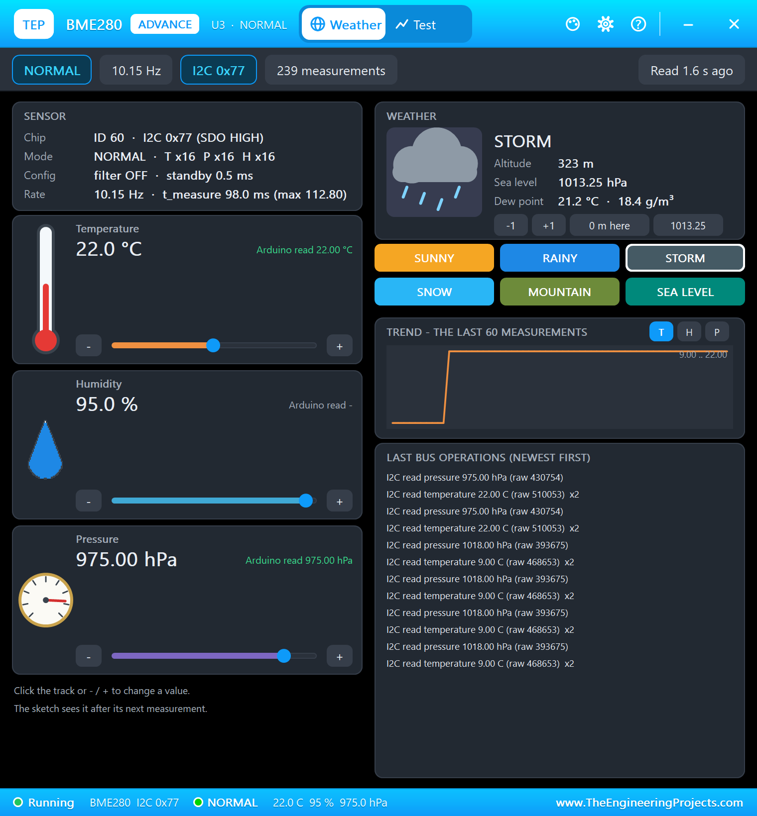
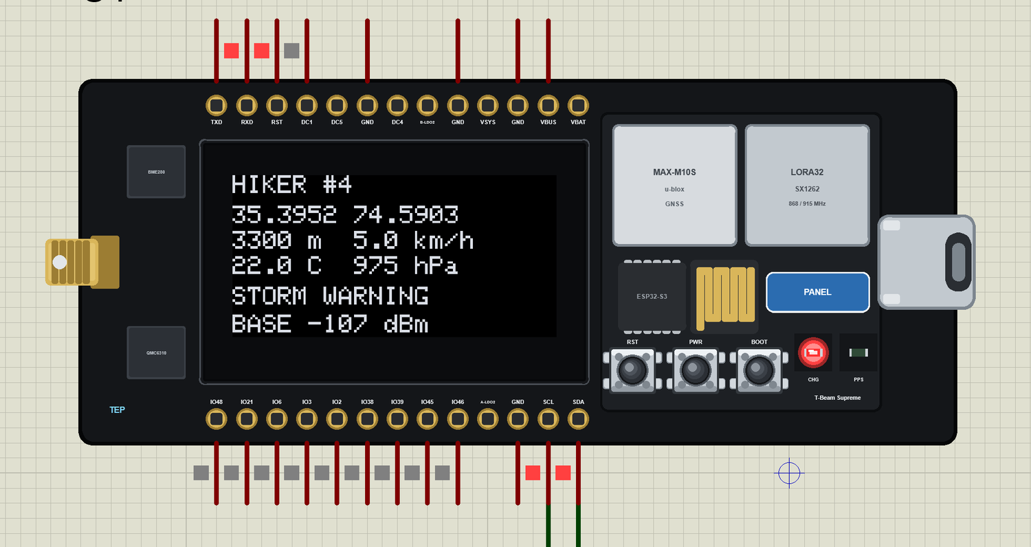
>> STORM WARNING: 975.0 hPa
TX #4 (weather): H,4,3539517,7459020,3300,220,974,1,0
The base camp heard #4, RSSI -107.0 dBm
>> SOS ON
TX #5 (BOOT): H,5,3539521,7459027,3300,220,974,1,1
The base camp heard #5, RSSI -107.0 dBm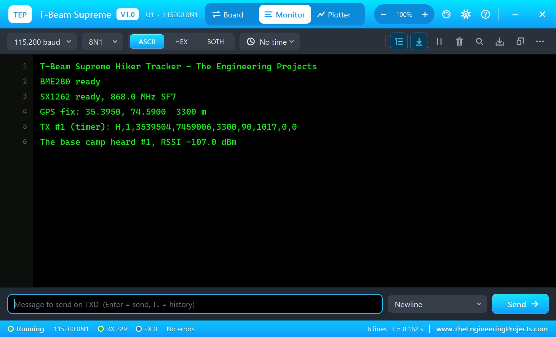
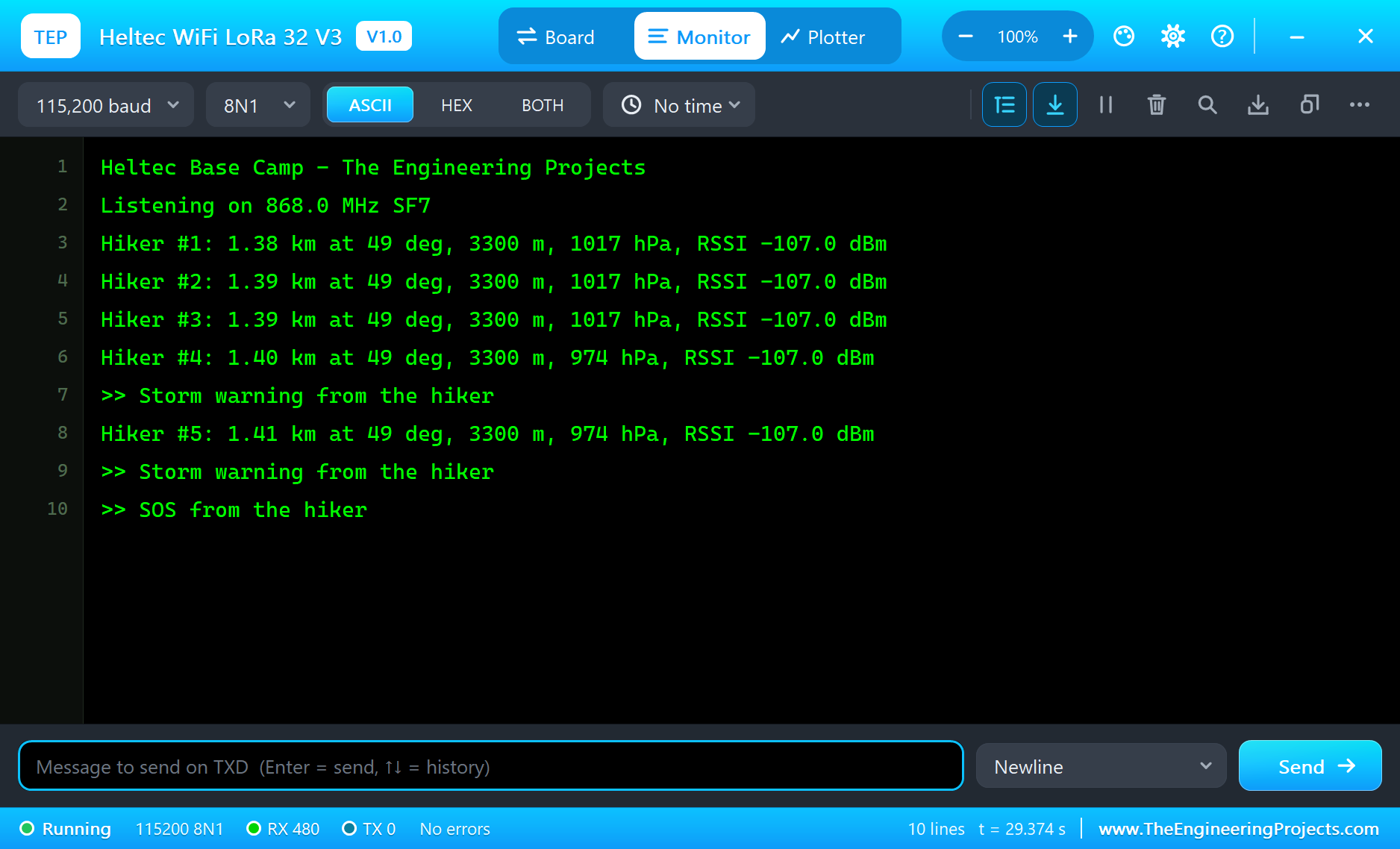
The base camp prints what it worked out:
Listening on 868.0 MHz SF7
Hiker #1: 1.38 km at 49 deg, 3300 m, 1017 hPa, RSSI -107.0 dBm
Hiker #2: 1.39 km at 49 deg, 3300 m, 1017 hPa, RSSI -107.0 dBm
Hiker #3: 1.39 km at 49 deg, 3300 m, 1017 hPa, RSSI -107.0 dBm
Hiker #4: 1.40 km at 49 deg, 3300 m, 974 hPa, RSSI -107.0 dBm
>> Storm warning from the hiker
Hiker #5: 1.41 km at 49 deg, 3300 m, 974 hPa, RSSI -107.0 dBm
>> Storm warning from the hiker
>> SOS from the hiker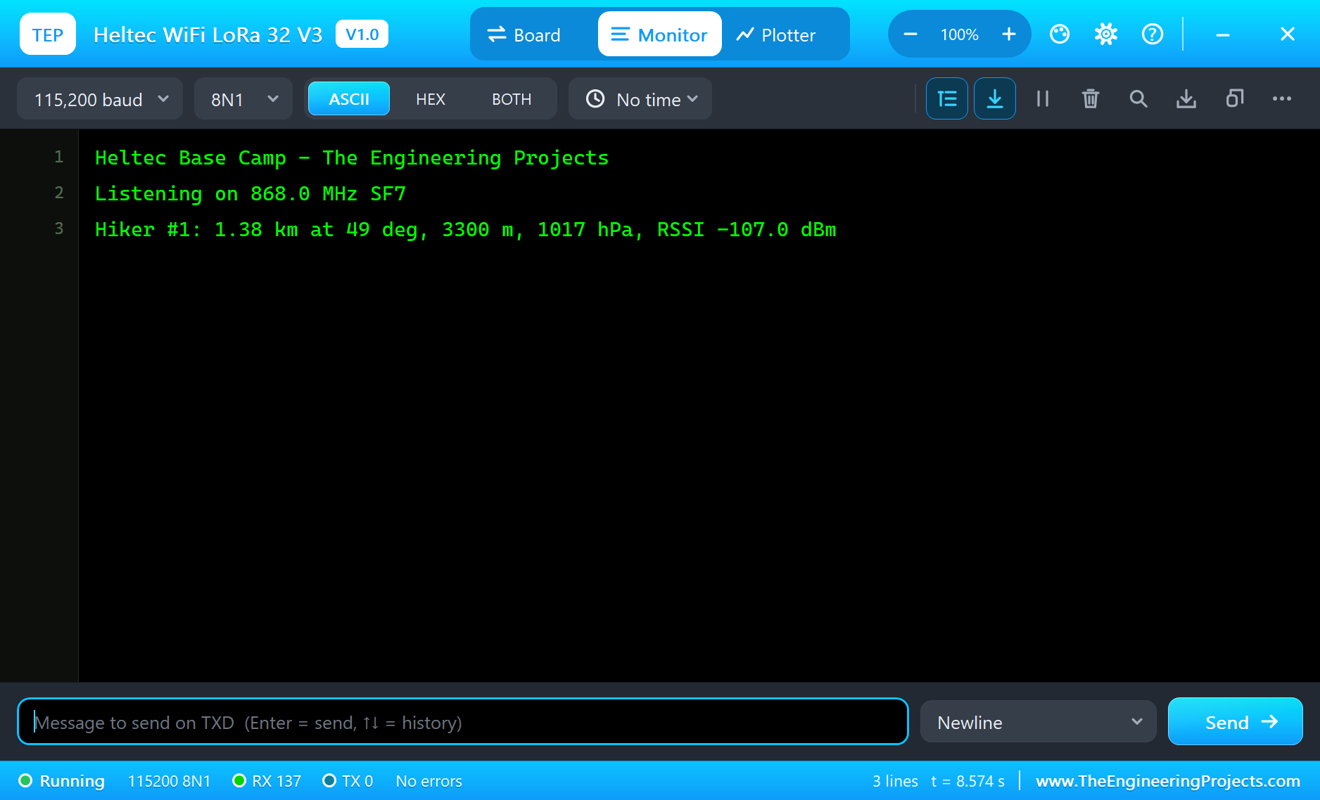
The Storm Comes
Click STORM on the BME280's window. The pressure drops, the sketch sends a packet at once instead of waiting for the next five seconds, and both screens warn:
SOS
Press BOOT on the board, or its key on the monitor's Board tab. SOS goes out at once, the hiker's OLED shows SOS ON, the base camp's OLED shows the alarm, and its white LED lights. LoRa has no way to avoid a collision, so a packet can be lost when both radios talk at once. That is why the sketch sends an SOS again every 1.5 s until the base camp's answer carries its number:
Try It Yourself
- Set
LORADISTon U1 to 10 km or 20 km and watch the RSSI fall, then the packets stop. - Set
GPSSPEEDto 40 andGPSHEADINGto 180, and let the tracker ride down the valley on a jeep. - Change
STORM_FALLand rebuild the sketch. - Click SUNNY on the BME280 and watch the warning clear.
Ideas to Extend the Tracker
- Send the packet every 30 s while nothing changes, to save the battery.
- Add a second T-Beam Supreme, so that two hikers can see each other, as Meshtastic does.
- Log the track to the TF card on a real board.
- Add Wi-Fi at the base camp and show a map in a browser.
Your Own Sketches
Write the sketch in the Arduino IDE with the board T-Beam Supreme (TEP Proteus), use Sketch > Export Compiled Binary and set the board's PROGRAM property to the .hex. LilyGO's names for the pins are defined, so RADIO_CS_PIN, GPS_RX_PIN and I2C_SDA all work.
Things to Know Before Using a Real T-Beam Supreme
- Power first: the radio, the GPS and the OLED get their power from the AXP2101. A real sketch must turn those rails on with LilyGO's XPowersLib before anything else. Our model keeps them always on.
- Two I2C buses: the OLED, compass and BME280 are on SDA 17 and SCL 18, and the clock and the AXP2101 on SDA 42 and SCL 41.
- Antenna first: never transmit with the SMA socket empty, and use an antenna for your band.
- Know your region: 868 MHz in Europe, 915 MHz in the Americas, and check the rules of your own country before you transmit.
- Two GNSS modules: the board ships with a MAX-M10S or an L76K, so read the module on your core.
- The GPS needs the sky: the simulation gives a fix after a few seconds; a real receiver needs an open view and much longer.
Properties of the T-Beam Supreme
| Property | What it does |
|---|---|
| PROGRAM | the sketch: a .hex from TEP Boards for Proteus (board "T-Beam Supreme") |
| LORADIST | the LoRa distance to the other boards, 10 m to 20 km |
| GPSLAT, GPSLON, GPSALT | where the GPS starts and its height |
| GPSSPEED, GPSHEADING | how it moves: km/h and degrees |
| GPSSATS, GPSFIX | the satellites and the seconds to the first fix |
| WIFISSID, WIFIPASS | the router in range (TEP-WiFi, 12345678) |
| MONITOR, BAUD, AUTOOPEN | the built-in serial monitor: on, its baud rate (115200), open at Run |
Troubleshooting
- RadioLib returns an error at the start: use
new Module(10, 1, 5, 4). - No packet arrives: both boards need the same frequency, bandwidth, spreading factor and sync word.
- Packets go out but no answer comes back: call
radio.startReceive()after each transmit. - The OLED picture is shifted: it is an SH1106, so start at column 2.
- The BME280 is not found: the demo's sensor is at 0x77, with SDO HIGH.
- A number goes wrong above 32767: int is 16 bits in the simulation - use long.
Limitations of the Simulation
- Your sketch gets 8 KB of RAM in the simulation, and there are no FreeRTOS tasks and no second core.
- The AXP2101, the board's own BME280, QMC6310, QMI8658 and clock, the TF card, the second I2C bus and the battery are not modelled.
- The GPS sends NMEA and ignores UBX commands. Bluetooth is not modelled.
- T-Beam is a name of LilyGO, SX1262 of Semtech and ESP32-S3 of Espressif Systems; this library is not made or endorsed by them or by Labcenter.
- Tested in Proteus 8.5 in October 2026 (the demo as shipped, about 30 s of simulation). Proteus 7 is not supported.
So, that was all about the LilyGO T-Beam Supreme Library for Proteus. I hope it helps you try your LoRa and GPS ideas long before you carry them up a mountain - the radio, the GPS, the OLED and the storm warning in one simulation. If you have any questions, ask in the comments and I will help you out. Till the next tutorial, take care and have fun!

Comments
0