


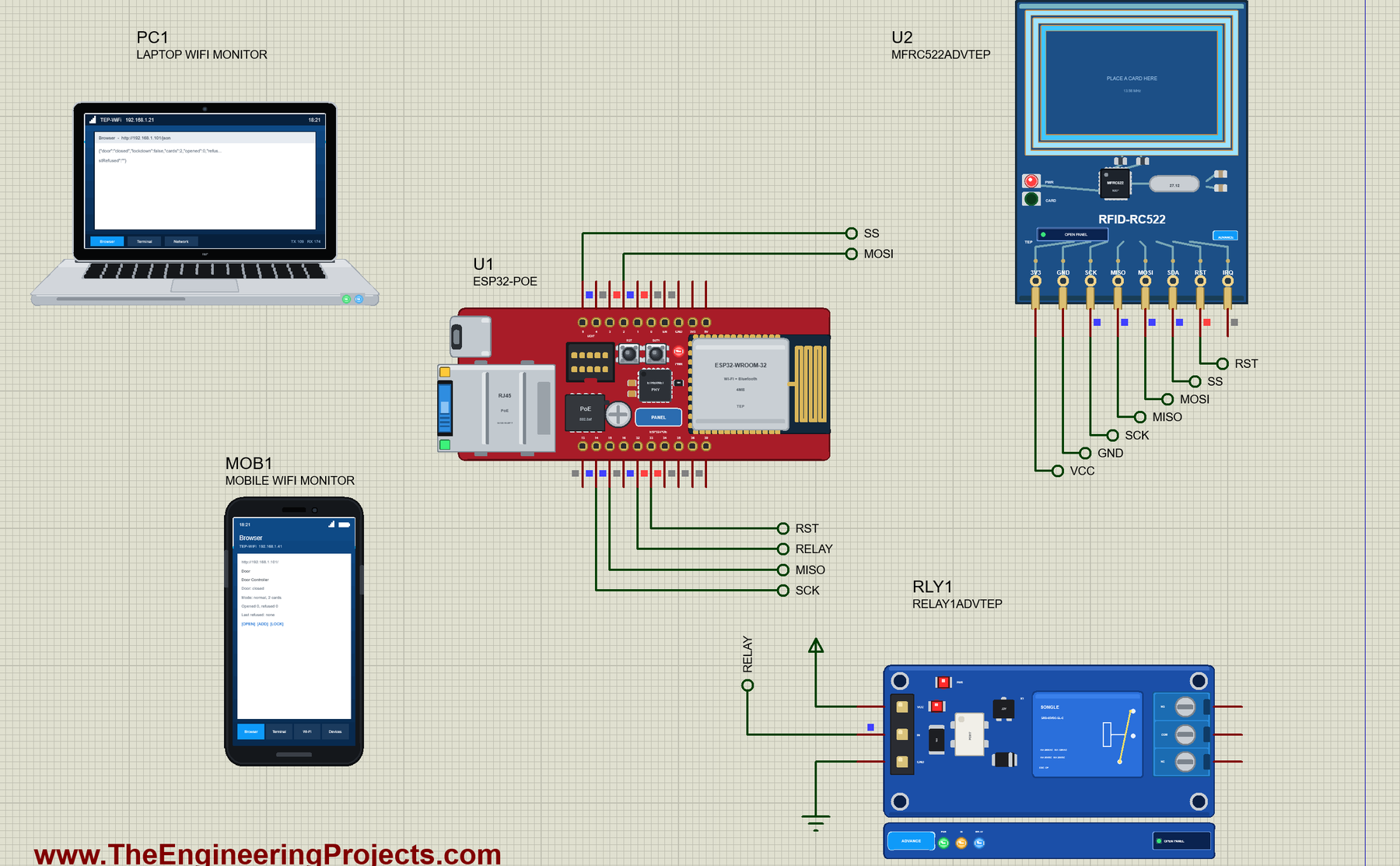
Olimex ESP32-POE Library for Proteus: RFID Door Controller


Hello friends, I hope you all are doing great. Today, I am going to share the Olimex ESP32-POE Library for Proteus. The ESP32-POE is a small red board from Olimex with an ESP32 and something most ESP32 boards do not have: a real Ethernet jack that also carries its power. One network cable feeds the board and connects it, so there is no power supply to hide and no Wi-Fi to fail. With this library the board runs your ESP32 Arduino sketch in Proteus 8.5, and ETH.begin() brings up the cable just as on the real hardware.
Olimex ESP32-POE Library for Proteus
Latest version: V1.0 (November 2026, this tutorial)
Helping Tools
- Laptop WiFi Monitor: a laptop on the Wi-Fi of your design: a browser, a TCP / UDP terminal and ping
- Mobile WiFi Monitor: a smartphone that opens the pages of your board and sends it commands
- Serial Monitor Advance: a serial terminal window for the UART of your board
For the demo we built the job this board was made for: a door access controller. An MFRC522 RFID reader checks the cards, a relay drives the door strike, and a phone and a laptop on the network see every event, add a new card and put the door into lockdown from the board's web page.
NOTICE: Proteus has no ESP32 model, so our team has put a lot of effort into building this board ourselves: the ESP32-POE's pins, buttons, Ethernet and Wi-Fi are all our own model, and your sketch compiles with our free TEP Boards for Proteus add-on. Your feedback is the fuel that keeps us going, so please tell us what you think in the comments below or in the Olimex ESP32-POE board of our forum. And if our free libraries help you, you can buy us a coffee. So, let's get started with the Olimex ESP32-POE Library for Proteus:
What is the Olimex ESP32-POE?
The ESP32-POE is an open-source development board from the Bulgarian company Olimex. It measures 80 x 28 mm and carries an ESP32-WROOM module with Wi-Fi and Bluetooth, a 100 Mbit Ethernet interface with IEEE 802.3af Power over Ethernet, a micro USB port with a programmer, a microSD slot, a LiPo battery connector with a charger, a user button, a reset button, a UEXT connector for Olimex's add-on modules and two 10-pin extension headers. It is a popular choice when a sensor or a controller has to run for years in a fixed place.
| ESP32-POE | WT32-ETH01 | ESP32 DevKit V1 | |
|---|---|---|---|
| Ethernet | yes, RJ45 with PoE | yes, RJ45 | no |
| Power | PoE, USB or LiPo | 5 V or 3.3 V pins | USB or VIN |
| Programming | micro USB on the board | a USB-to-serial adapter | micro USB on the board |
| Extras | microSD, UEXT, LiPo charger | none | none |
| Best for | fixed installations | small Ethernet gadgets | the bench |
What is Power over Ethernet?
Power over Ethernet, or PoE, sends DC power down the same cable as the data. The standard this board follows, IEEE 802.3af, runs at about 48 V and gives a device up to 12.95 W. A PoE switch does not simply switch 48 V on. It first looks for a small signature resistance on the line, and only then applies the power, so an ordinary laptop plugged into the same socket is safe. Inside the ESP32-POE a controller chip handles that handshake, and a small transformer steps the 48 V down to the 5 V and 3.3 V the board needs. The result is lovely for an installer: one cable, one socket on the switch, and the switch's own backup supply keeps every door in the building alive during a power cut.
Why Use Ethernet Instead of Wi-Fi?
Wi-Fi is wonderful until a metal door frame, a crowded band or a changed password gets in the way. A door controller cannot afford that. A cable gives a steady link with no channel to share and no password to expire, and on a PoE switch the same cable brings the power. The ESP32 keeps its Wi-Fi as a spare, so the two can back each other up.
Features of the Olimex ESP32-POE Library for Proteus
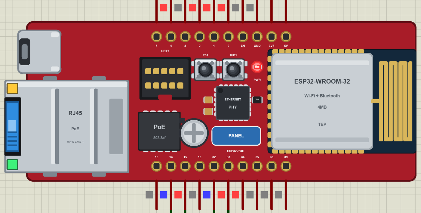
- The board as it looks: the red ESP32-POE with the RJ45 jack and its LEDs, the micro USB, the PoE transformer and capacitor, the UEXT connector, RST and BUT1, the Ethernet PHY and the ESP32-WROOM-32 module with its PCB antenna.
- Your sketch: a .hex for "ESP32-POE (TEP Proteus)" with the board's GPIO numbers - analogRead 0 to 4095, analogWrite and ledc PWM, attachInterrupt, Serial, Serial2, Wire and SPI.
- Ethernet: the ETH library -
ETH.begin()with no arguments, DHCP or a fixed address, the link events - and WebServer, HTTPClient and mDNS over the cable; the board is 192.168.1.101 in the demo. - A cable you can pull: the jack shows the plug and its green and yellow LEDs; a click on the jack pulls the cable and the sketch gets the event.
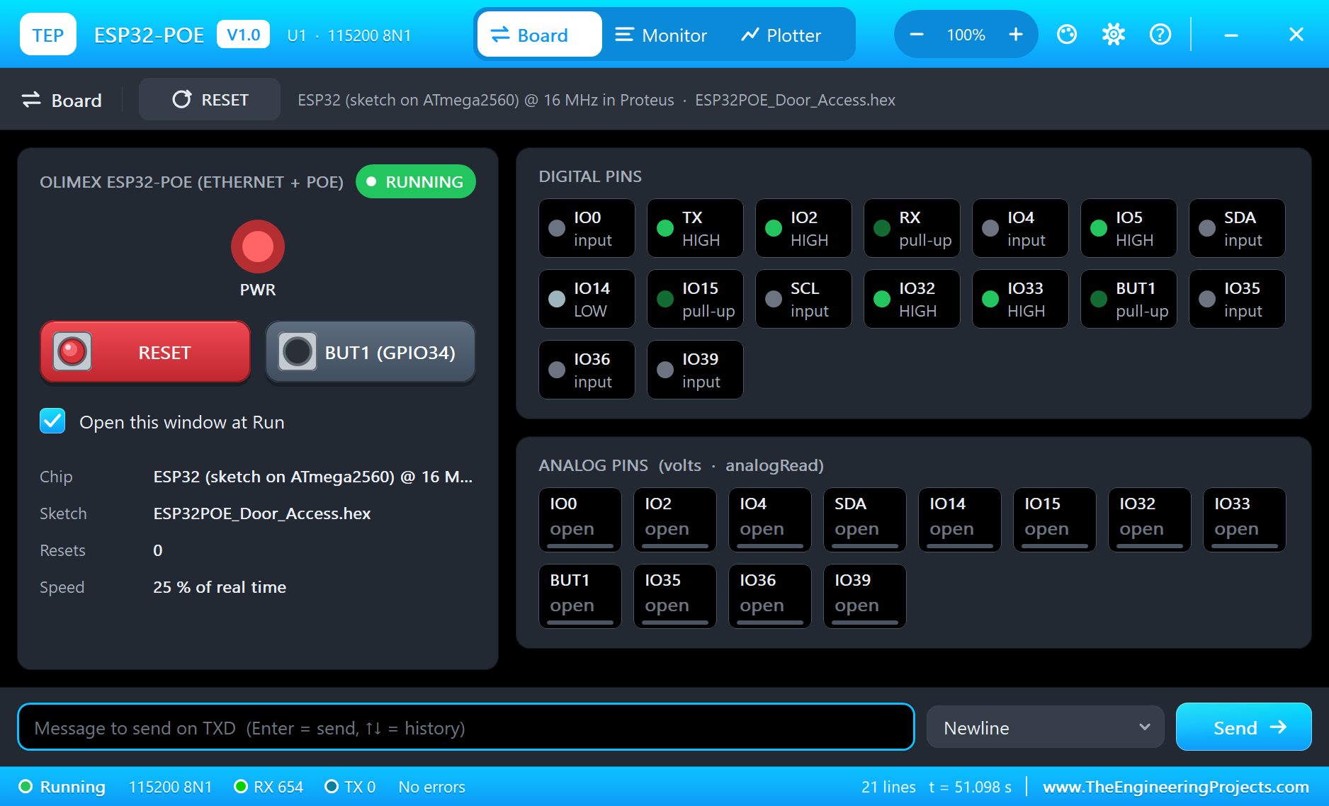
- The panel and the serial monitor: the board's panel (Wi-Fi, Pins, Test) and the built-in serial monitor with Monitor, Plotter and Board tabs - our TEP header, no Windows title bar.
- A complete package: about 3.8 MB with the board, the add-on, the MFRC522, relay and monitor libraries and the demo, without the source code of the models.
The ESP32-POE in Proteus
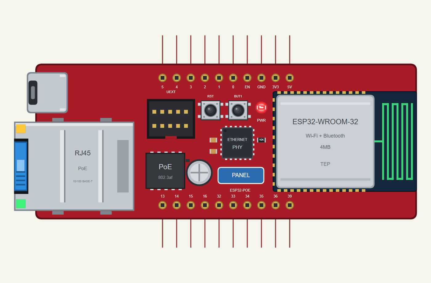
Search ESP32-POE in Pick Devices; the device is in TEPESP32POE.LIB (Microprocessor ICs, ESP32 Boards), with the prefix U. The board lies with the jack on the left and the antenna on the right. Click the micro USB to open the serial monitor, and the PANEL pad (or the module) to open the board's panel.
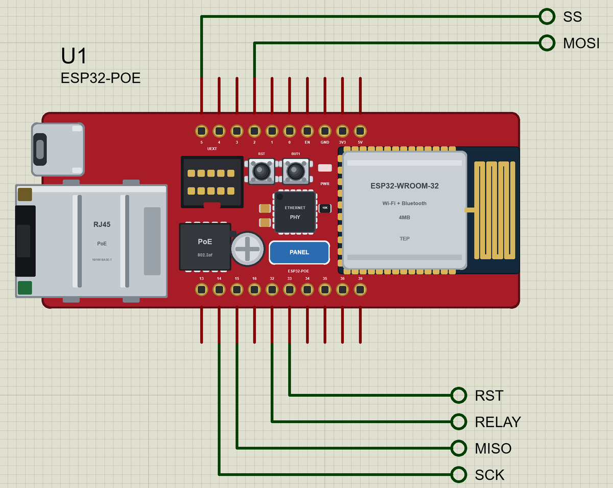
The Pins
| Pins | GPIO | What the library does with them |
|---|---|---|
| SDA / SCL | 13 / 16 | Wire |
| SS, MOSI, MISO, SCK | 5, 2, 15, 14 | SPI |
| TX / RX | 1 / 3 | Serial, the board's monitor |
| TX2 / RX2 | 33 / 35 | Serial2 |
| Free pins | 0, 4, 32 | GPIO, PWM, interrupt |
| Inputs only | 34, 35, 36, 39 | digital and analog inputs |
| BUT1 | 34 | the user button, LOW when pressed |
| 3V3, 5V, GND, EN | - | the supplies and the reset |
The labels on the board are the plain GPIO numbers, as in Olimex's pinout chart. The Ethernet chip uses GPIO12, 17, 18, 19, 21, 22, 23, 25, 26 and 27 inside the board, which is why those numbers do not appear on the headers, and why I2C and SPI sit on different pins from a DevKit.
Download Olimex ESP32-POE Library for Proteus
Click the button below to download Olimex-ESP32-POE-Library-for-Proteus-v1.0.zip (about 3.8 MB, without the source code of the models):
Olimex ESP32-POE Library for Proteus V1.0- README.txt: installation, the demo, the pins, the properties, troubleshooting and the limits.
- Proteus Library Files:
TEPESP32POE.LIBand the demo's parts:TEPMFRC522.LIB,TEPRELAY.LIB,TEPLAPTOP.LIBandTEPMOBILE.LIB. - Proteus Model Files:
TEPNET.DLL(the board, the laptop, the phone and the network),TEPMFRC522.DLLandTEPRELAY.DLL. - Arduino Code: the demo sketch and the TEP Boards for Proteus add-on 1.44.0.
- Proteus Simulation: the demo project, its HEX file and copies of the DLLs.
No Proteus yet? Read How to Download and Install Proteus 7 and 8. New to libraries? Follow How to Install a New Library in Proteus.
How to Install Olimex ESP32-POE Library for Proteus
- Close Proteus and extract the whole zip file, for example to your Desktop.
- Copy the files from Proteus Library Files into the LIBRARY folder of Proteus.
- Copy the DLLs from Proteus Model Files into the MODELS folder, replacing an older TEPNET.DLL.
- Delete
TEPESP32POE.IDXfrom the LIBRARY folder if it is there. - For your own sketches, copy Arduino Code\TEP Boards for Proteus\hardware into your Arduino sketchbook (Documents\Arduino) and restart the Arduino IDE; the board is ESP32-POE (TEP Proteus). Install MFRC522 from the Library Manager.
- Start Proteus, press P and search for ESP32-POE.
Demo: an RFID Door Controller
Walk into any modern office and you will find small boxes above the doors doing exactly this job: reading a card, checking a list, and releasing a lock for a few seconds. Most of them are on the building's network, so that a guard can see who came in and lock a whole floor from one screen. Ours does the same, with a list of cards, a five-line event log, a web page and a lockdown button.
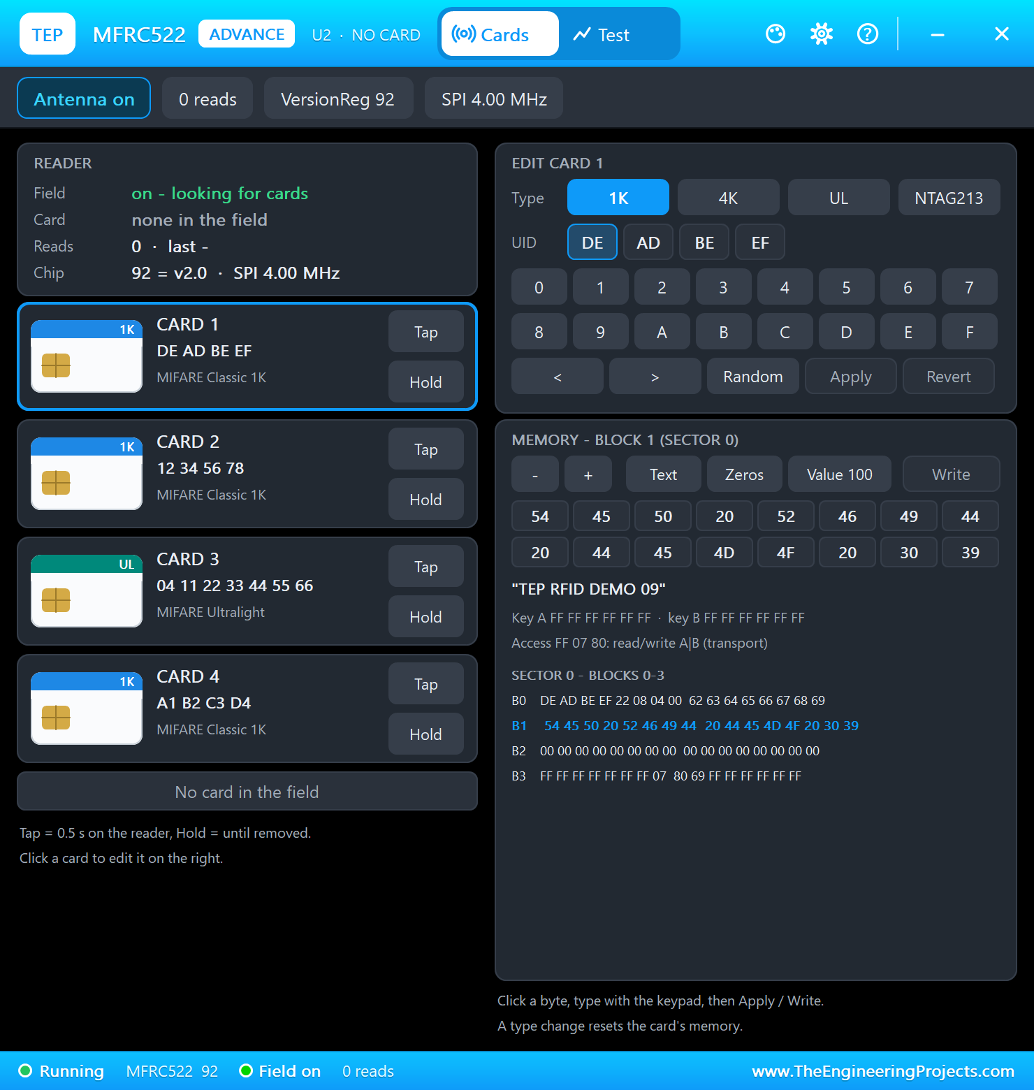
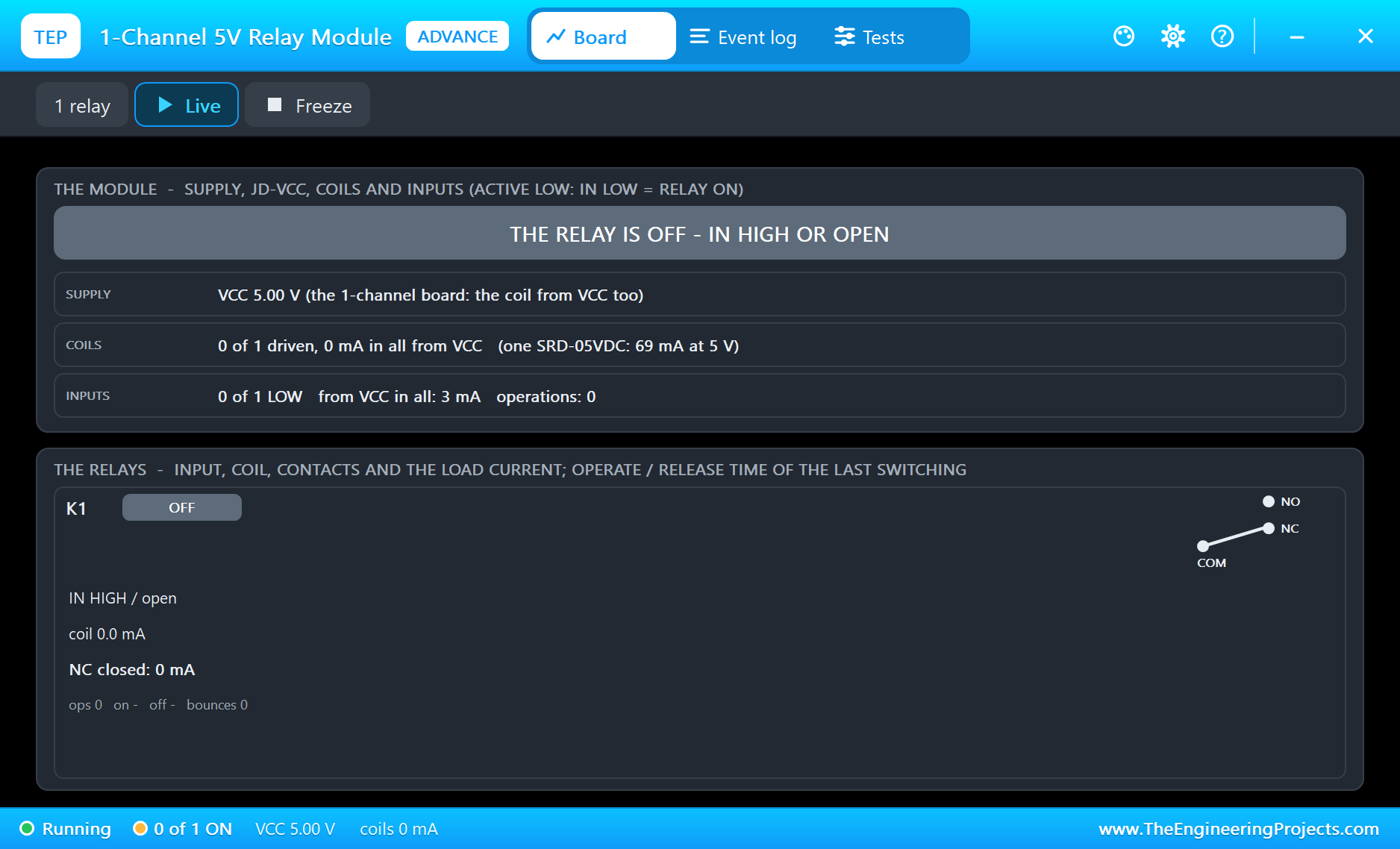
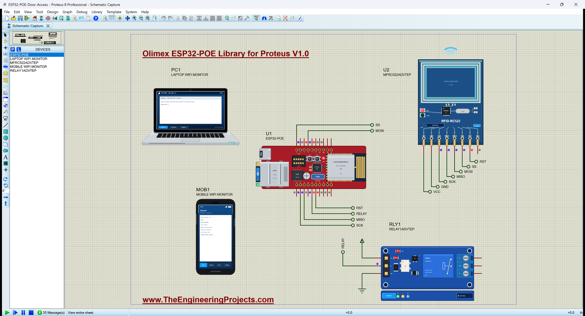
Open ESP32-POE-Door-Access.pdsprj. U1 runs ESP32POE_Door_Access.hex. U2 is the reader from our MFRC522 RFID Library for Proteus and RLY1 the door strike's relay from our Relay Module Library for Proteus - both in the Advance version, so they open their pop-up windows at Run. PC1 is the Laptop WiFi Monitor and MOB1 the Mobile WiFi Monitor. Nothing is wired to them: the board's own RJ45 is its cable to the router.
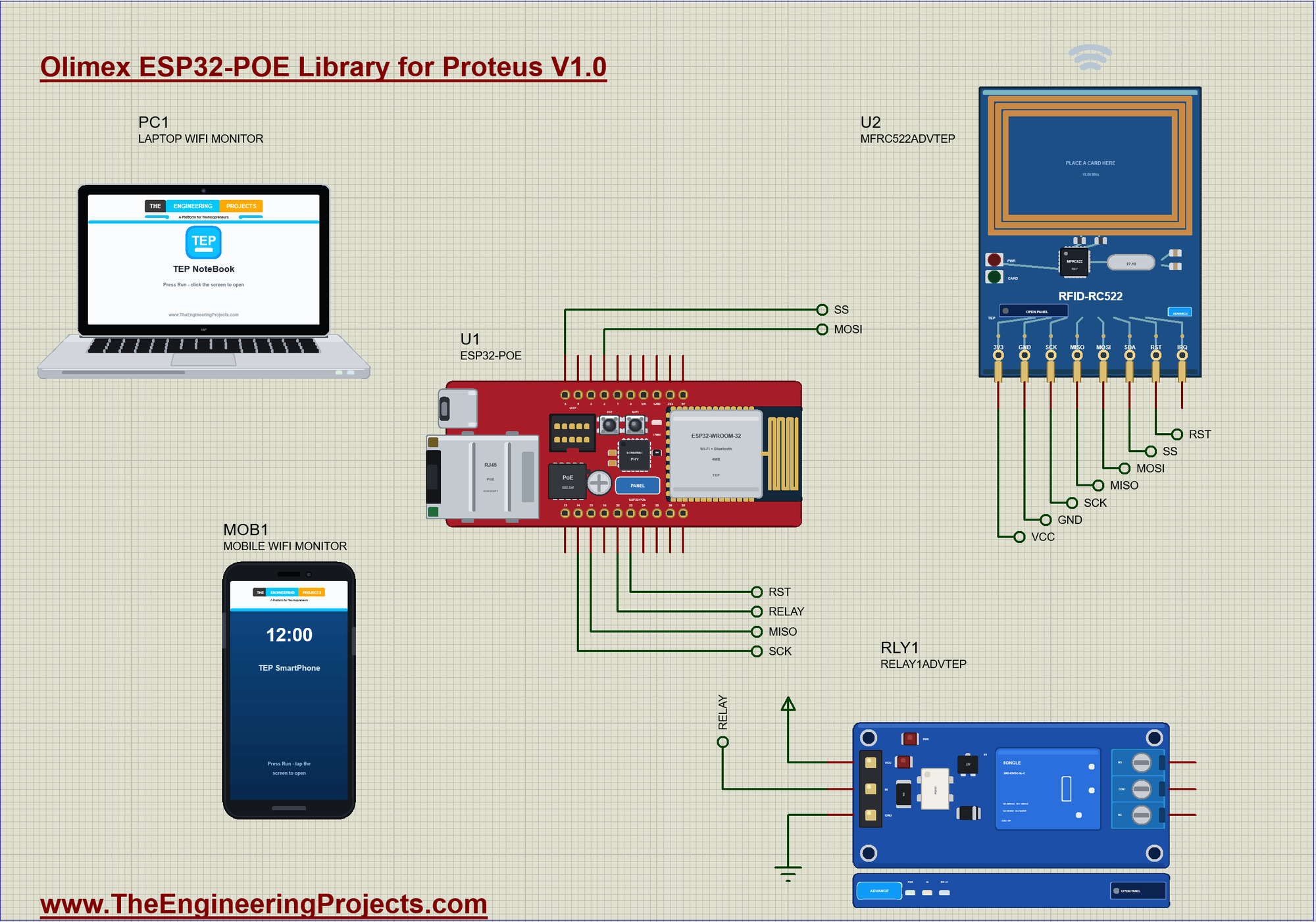
| Module pin | Net label | Board pin | What it does |
|---|---|---|---|
| MFRC522 SDA | SS | 5 | selects the reader on SPI |
| MFRC522 MOSI, MISO, SCK | MOSI, MISO, SCK | 2, 15, 14 | the SPI bus |
| MFRC522 RST | RST | 33 | resets the reader |
| MFRC522 3V3, GND | VCC, GND | 3V3, GND | the supply |
| Relay IN | RELAY | 32 | the door strike, active LOW |
| Relay VCC, GND | VCC, GND | 5V, GND | the supply |
Starting the Ethernet
The ETH library needs only one line, because the board's variant already knows the PHY's address, its management pins and its clock. What matters is the order: the sketch registers an event handler first and calls ETH.begin() second, so that it hears every step. The link comes up when the two ends agree on a speed, and a moment later DHCP gives the board its address. The handler also hears the cable being pulled, and the door keeps working on its own list, which is what you want during a network fault:
void onEvent(arduino_event_id_t event) {
  switch (event) {
    case ARDUINO_EVENT_ETH_CONNECTED:
      Serial.printf("ETH link up: %u Mbit/s\n", (unsigned)ETH.linkSpeed());
      break;
    case ARDUINO_EVENT_ETH_GOT_IP:
      Serial.print("Door page: http://"); Serial.print(ETH.localIP()); Serial.println("/");
      online = true;
      break;
    case ARDUINO_EVENT_ETH_DISCONNECTED:
      Serial.println("ETH link down - the door keeps working");
      online = false;
      break;
    default:
      break;
  }
}
How RFID Works
The MFRC522 talks to cards at 13.56 MHz. Its antenna makes a magnetic field, and a card held close to it powers up from that field alone, with no battery. The card then answers by loading the field in a pattern the reader can decode. Each card has a UID, a unique number of 4 or 7 bytes, and that is what we compare. The sketch polls five times a second, reads the UID, turns it into hex text and halts the card, so that one tap counts once:
void readCard() {
  if (millis() < nextScan) return;
  nextScan = millis() + 200;
  if (!rfid.PICC_IsNewCardPresent() || !rfid.PICC_ReadCardSerial()) return;
  String id = cardId();
  rfid.PICC_HaltA();
  if (lockdown) { refused++; addEvent("Locked: " + id); }
  else if (allowed(id)) openDoor(id);
  else { refused++; lastRefused = id; addEvent("Refused: " + id); }
}
The List of Cards
The list is a small array of text, and the check is a simple loop. Six cards are plenty for a demo; a real controller would keep hundreds in flash or ask a server:
bool allowed(const String &id) {
  for (byte i = 0; i < cardCount; i++) if (cards[i] == id) return true;
  return false;
}
The Door Strike
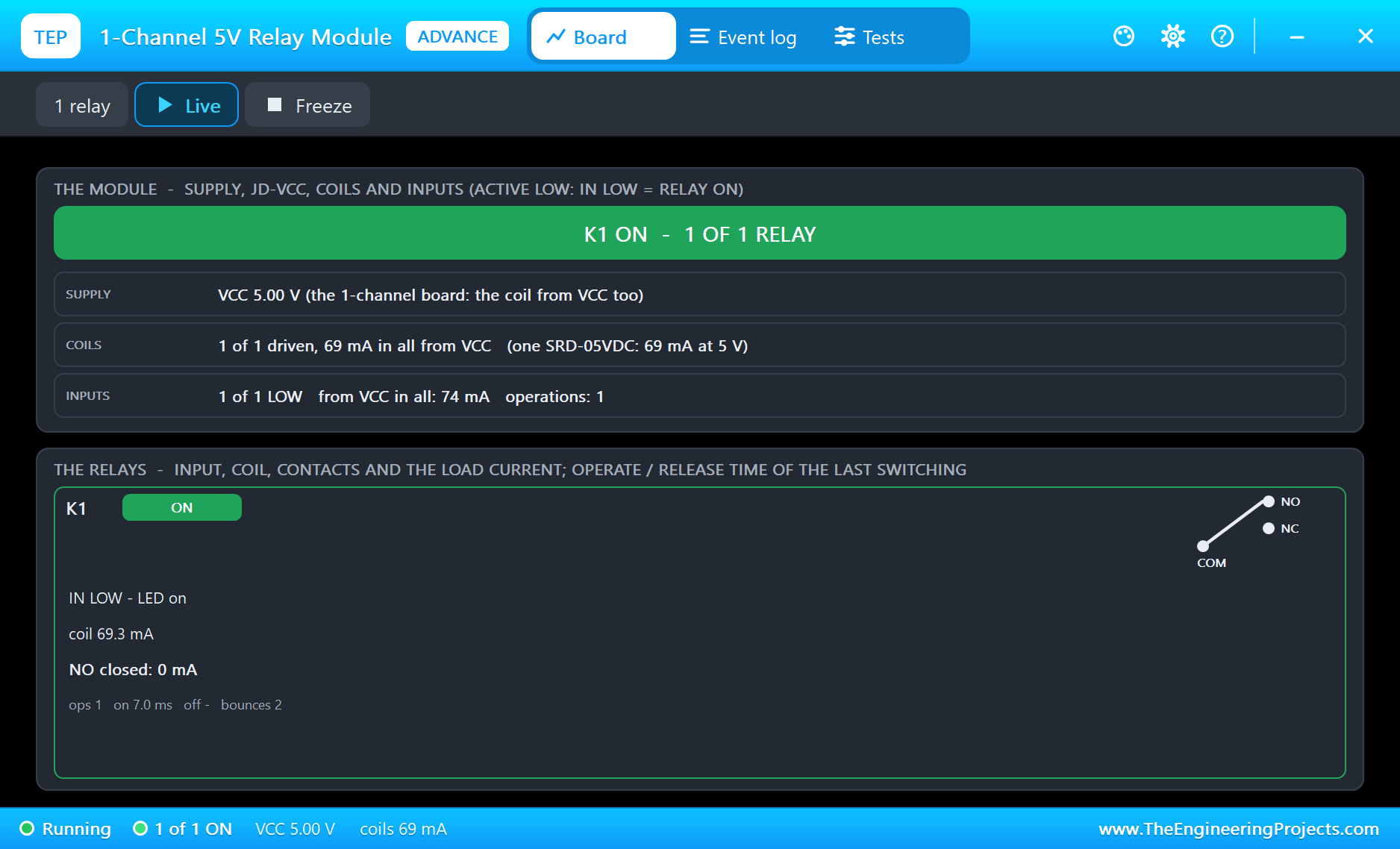
A door strike is an electric catch in the frame. A fail-secure strike stays locked without power, which suits a store room, and a fail-safe one opens without power, which is what fire rules demand on an escape route. The relay gives the strike its own 12 V circuit, far from the 3.3 V logic. Our relay module is active LOW, so a LOW on GPIO32 pulls the coil in:
void openDoor(const String &who) {
  digitalWrite(RELAY_PIN, LOW);                             // the relay module: LOW = on
  doorOpen = true;
  closeAt = millis() + OPEN_MS;
  opened++;
  addEvent("Open: " + who);
}
The sketch never waits for those 3 s. It notes the closing time and carries on, so the reader and the web server stay awake while the door is open:
void closeDoor() {
  if (!doorOpen || millis() < closeAt) return;
  digitalWrite(RELAY_PIN, HIGH);
  doorOpen = false;
  Serial.println("Door closed");
}
The Event Log
Every event goes to the monitor and to a list of the last five, newest first. Moving the older lines down one place is a very small job with five entries, and a door log is the most useful thing on the page:
void addEvent(const String &text) {
  Serial.println(text);
  if (eventCount < MAX_EVENTS) eventCount++;
  for (byte i = eventCount - 1; i > 0; i--) events[i] = events[i - 1];
  events[0] = text;
}
The JSON Page
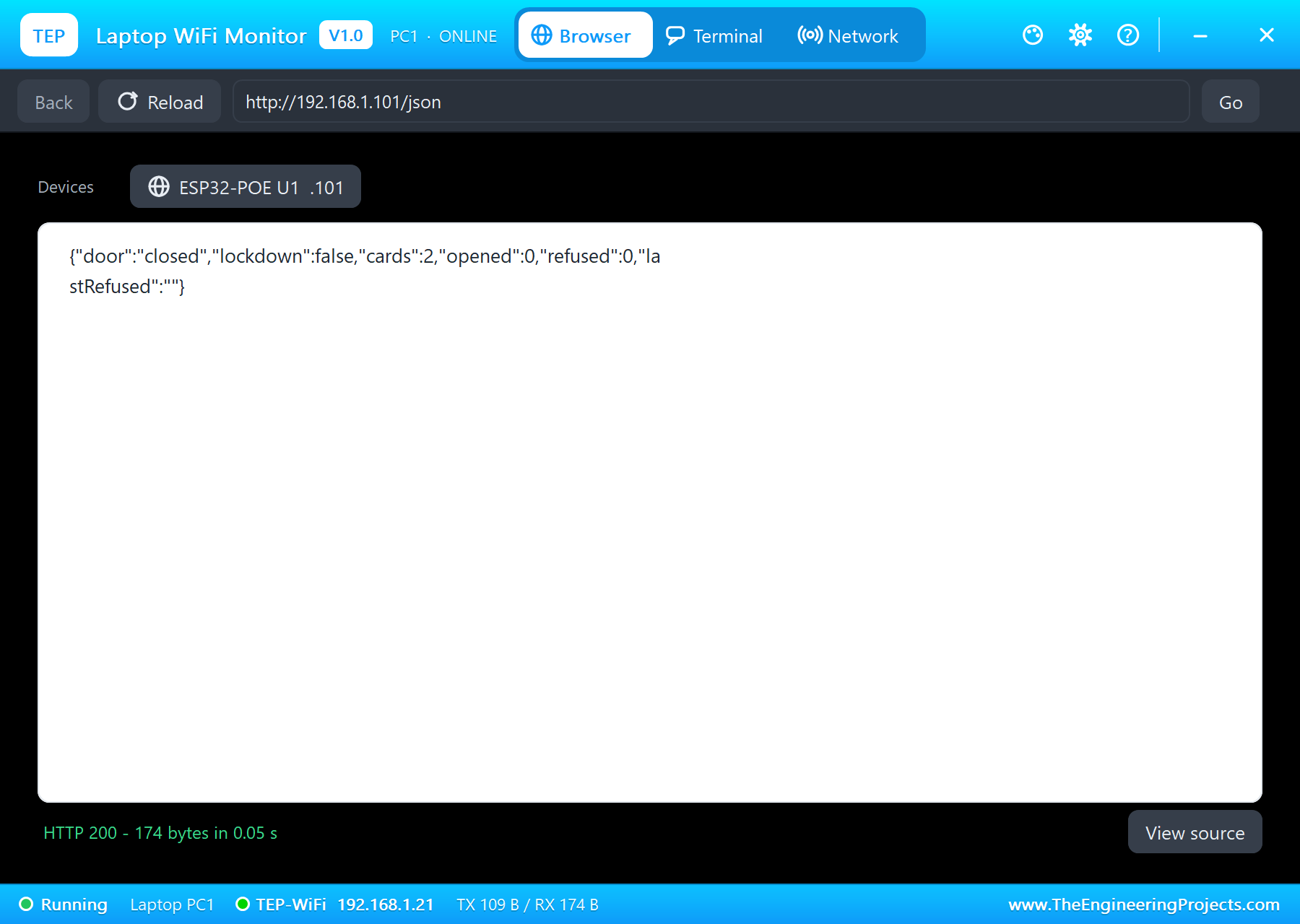
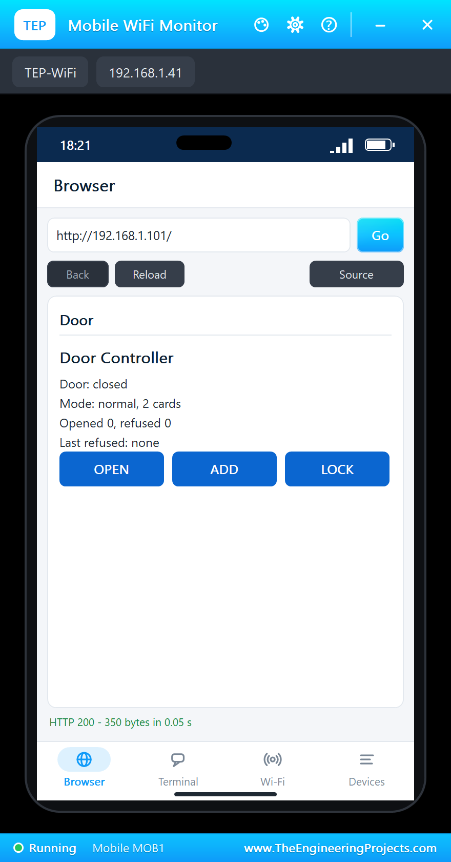
/ is the page for a person, with three buttons. /json is one line for a program, which is what the laptop opens. A central security system would read a line like this from every door in the building:
void handleJson() {
  String j = "{\"door\":\"" + String(doorOpen ? "open" : "closed") + "\",\"lockdown\":" + String(lockdown ? "true" : "false") + ",\"cards\":" + String(cardCount);
  j += ",\"opened\":" + String(opened) + ",\"refused\":" + String(refused) + ",\"lastRefused\":\"" + lastRefused + "\"}";
  server.send(200, "application/json", j);
}
Run the Demo
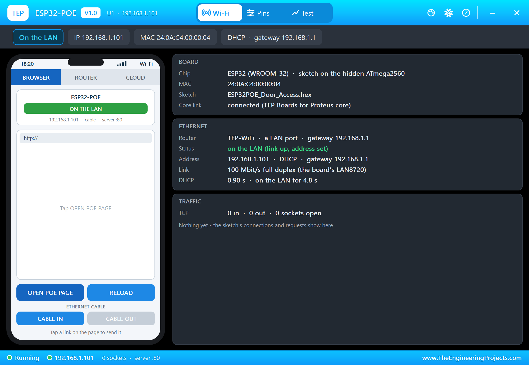
Press Run. The serial monitor opens and the reader reports its version. Then the two ends of the cable agree on 100 Mbit/s, the jack's LEDs light, and DHCP gives the board its address:
ESP32-POE Door Access - The Engineering Projects
MFRC522 version 0x92
ETH link up: 100 Mbit/s
Door page: http://192.168.1.101/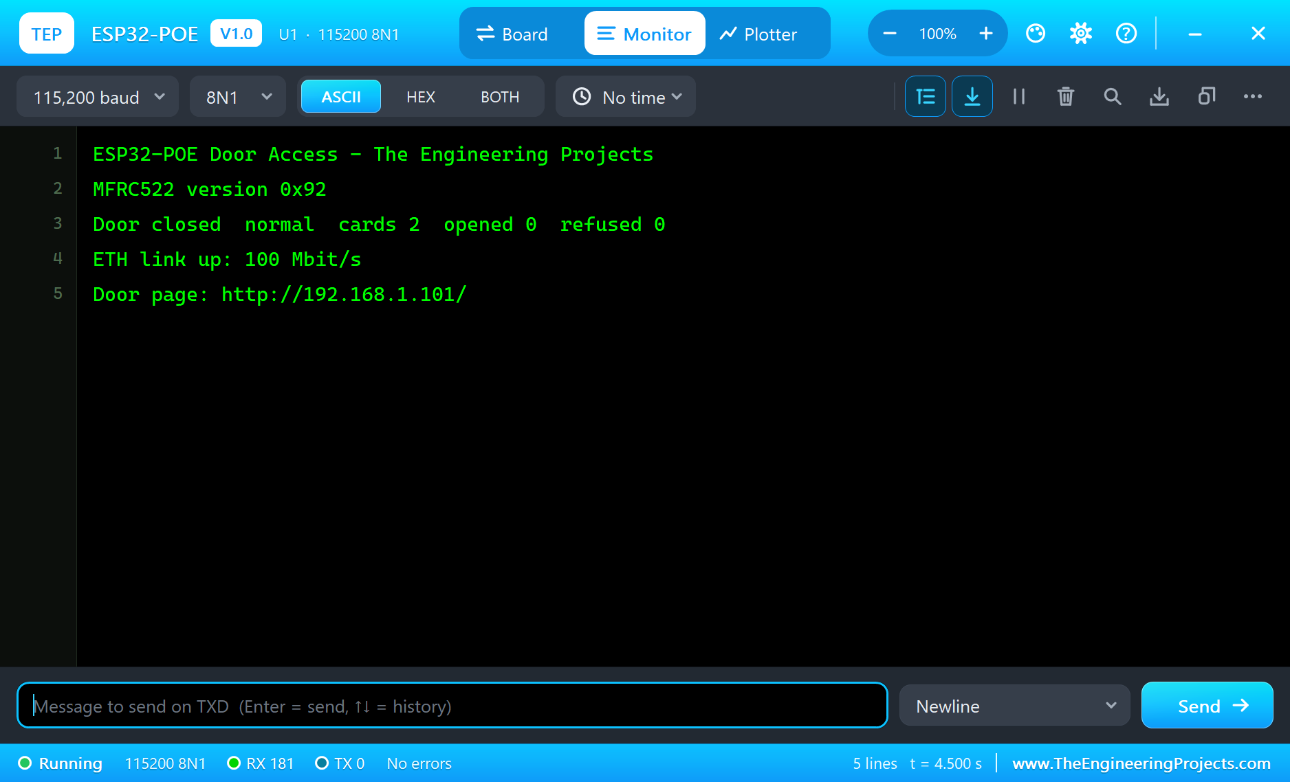
Open the Page
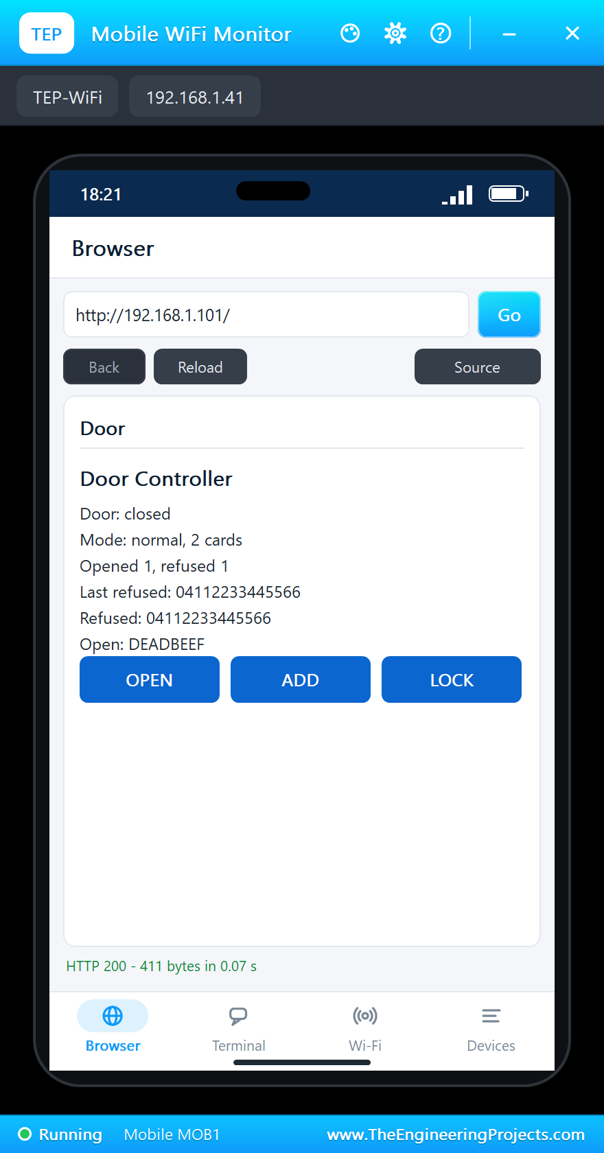
On the laptop click Browser and Go (the home page is http://192.168.1.101/json); on the phone the same with http://192.168.1.101/:
A Good Card
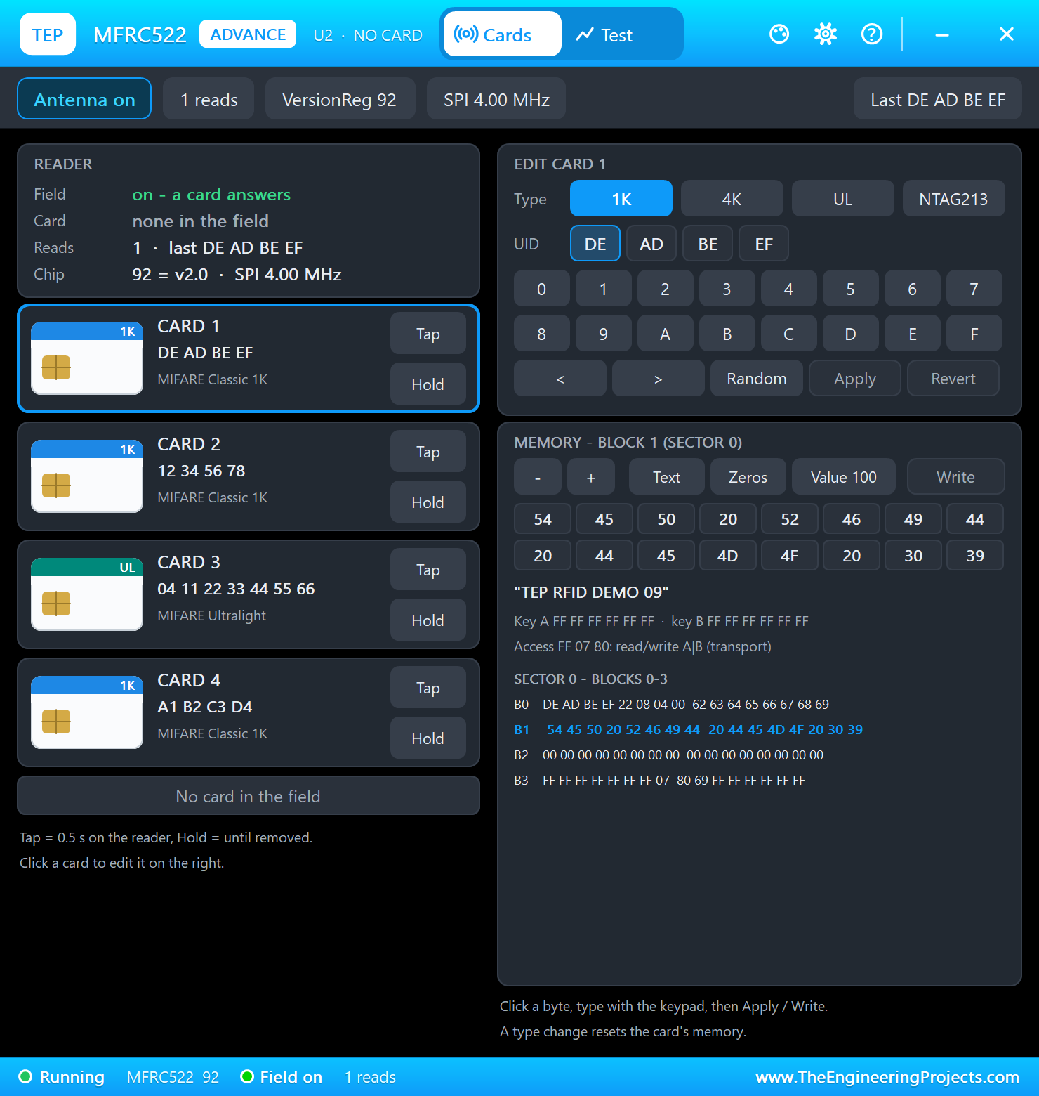
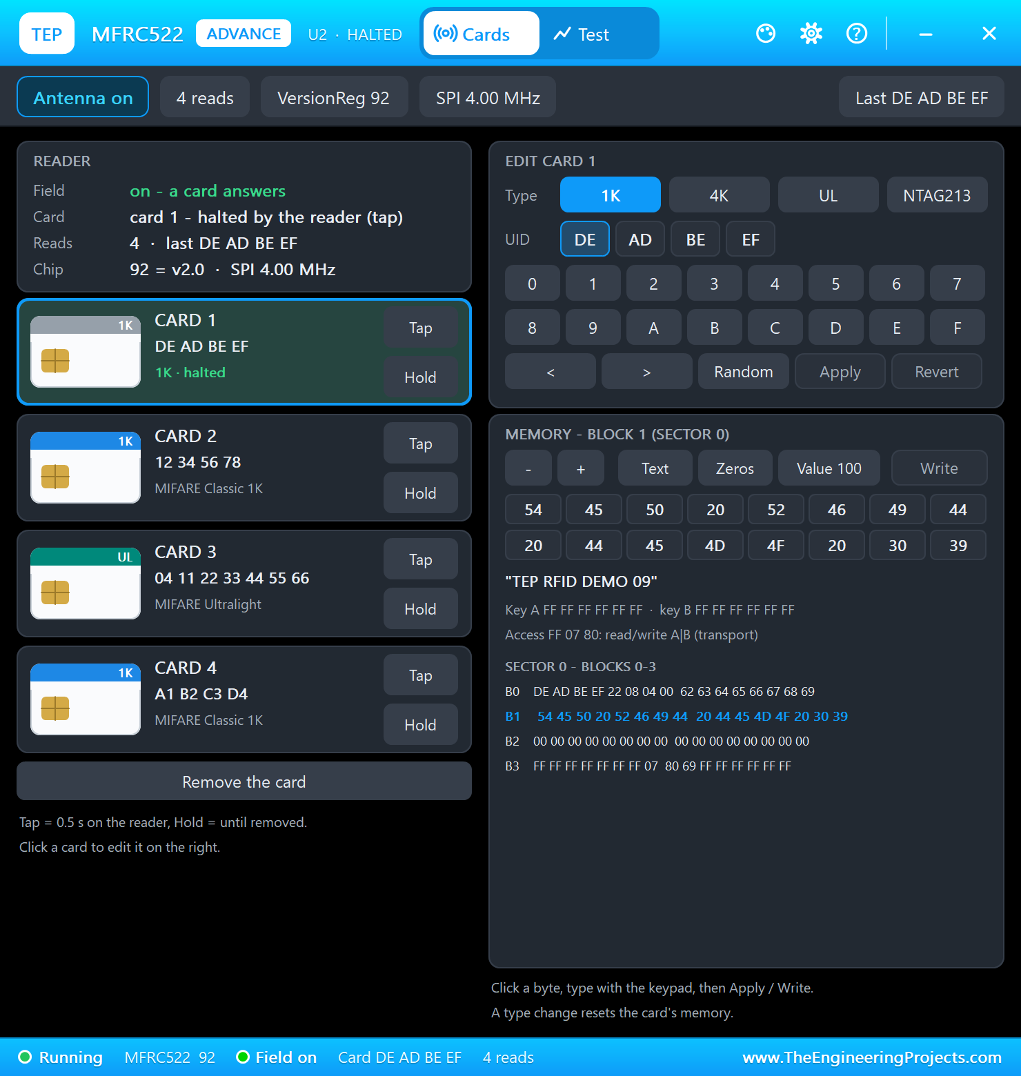
Click Tap on CARD 1 on the reader's pop-up. The card is on the list, so the monitor prints Open: DEADBEEF, GPIO32 goes LOW and the relay pulls in for 3 s:
A Card That Is Not on the List
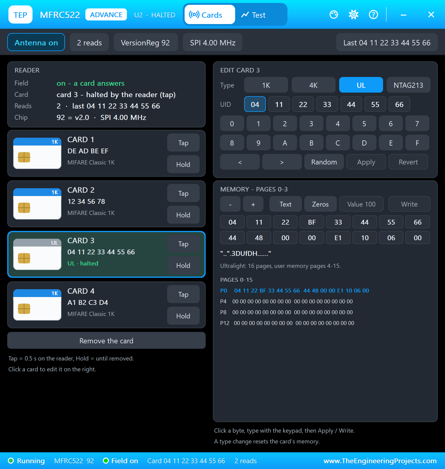
Click Tap on CARD 3. The monitor prints Refused: 04112233445566 and the relay stays off. After Reload the phone shows the card as the last refused:
Adding the New Card
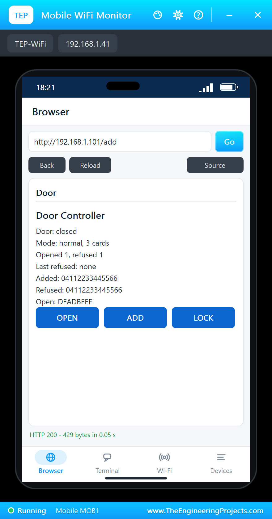
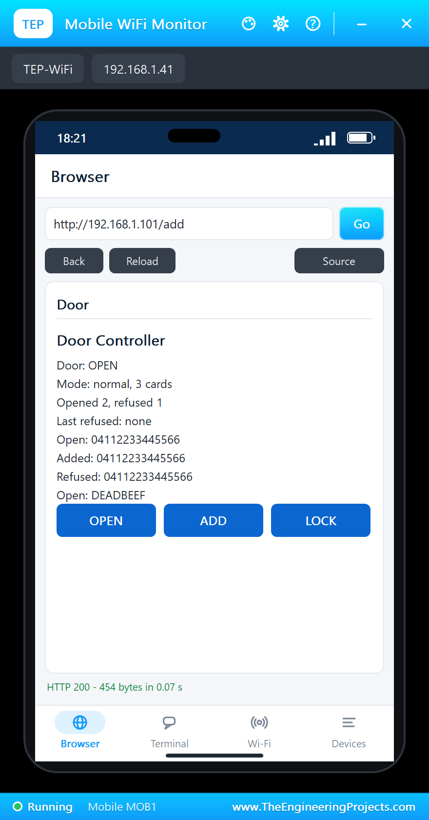
A new member of staff is at the door, so click ADD. The list grows to three cards, and the same card now opens the door:
Lockdown
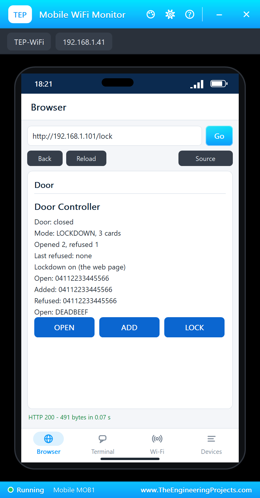
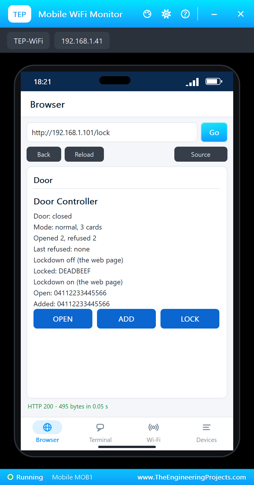
Click LOCK. Now no card works, not even card 1, and each try goes into the log. That is what a guard would do from a desk during an emergency:
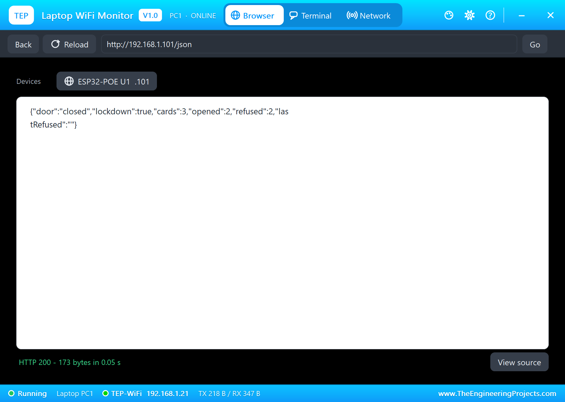
Click LOCK again to end it, then OPEN to release the door from the page:
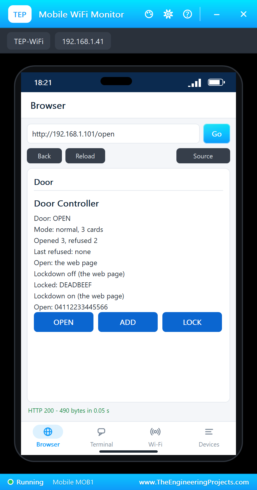
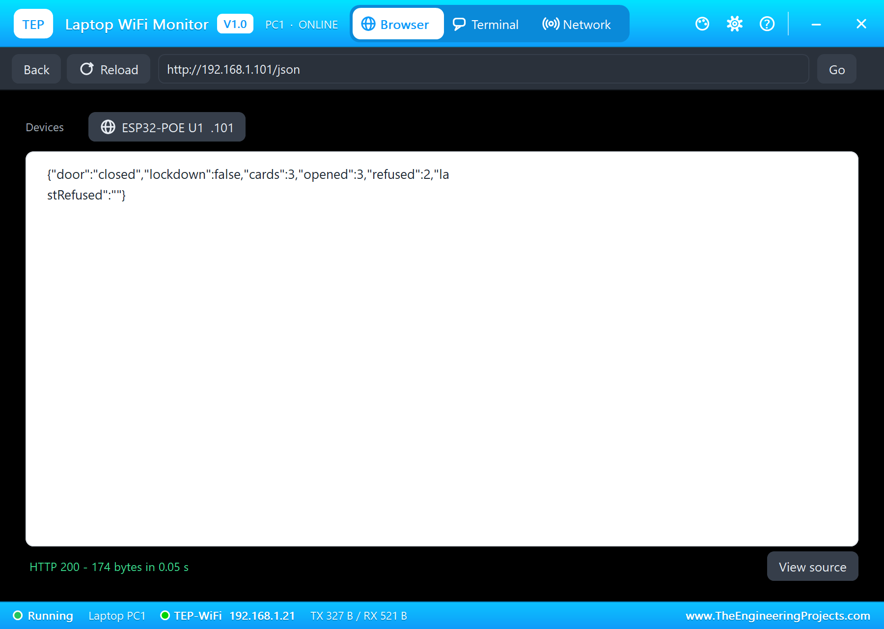
The built-in serial monitor, in the look of our TEP Serial Monitor Advance for Proteus, has followed everything:
Open: DEADBEEF
Door closed
Refused: 04112233445566
Added: 04112233445566
Open: 04112233445566
Door closed
Lockdown on (the web page)
Locked: DEADBEEF
Lockdown off (the web page)
Open: the web page
Door closed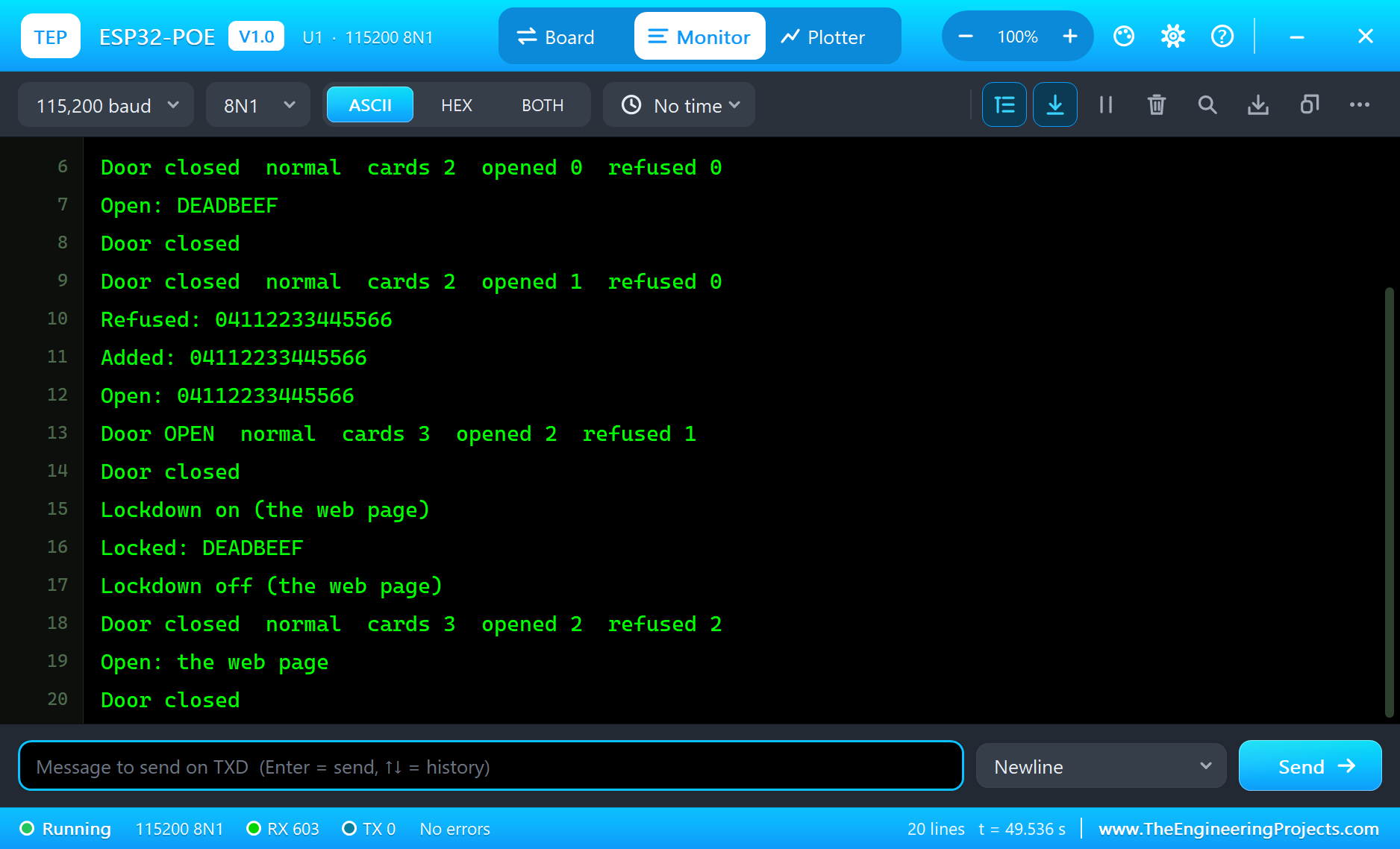
Try It Yourself
- Press BUT1 on the monitor's Board tab: it is the exit button, and the door opens from inside.
- Click the board's RJ45 jack to pull the cable, then tap a card: the door still answers.
- Hold a card on the reader with Hold and see that one tap counts once.
- Type
STATUS,OPENorLOCKin the monitor.
Ideas to Extend the Door Controller
- Save the list of cards in the microSD slot or in Preferences, so that it survives a reset.
- Add a clock and allow some cards only in working hours.
- Send each event to a server with HTTPClient, so that the log is kept for years.
- Add a door contact on a free pin and warn when the door stays open.
Your Own Sketches
Write the sketch in the Arduino IDE with the board ESP32-POE (TEP Proteus), use Sketch > Export Compiled Binary and set the board's PROGRAM property to the .hex. For a real board select "OLIMEX ESP32-PoE" in Espressif's "esp32" package and upload - the same sketch, with the same pin numbers.
Things to Know Before Using a Real ESP32-POE
- The board is not insulated: Olimex warns never to use USB or an external supply while PoE is powering the board. Unplug the cable before you connect USB, or use their insulated version.
- 4 W is the limit: the 5 V and 3.3 V outputs together must not draw more than 4 W, so a relay and a reader are fine, and a big strike needs its own supply.
- Boot pins: GPIO0 and GPIO2 set the boot mode, so take care what you connect to them.
- Shared pins: GPIO2, 14 and 15 also go to the microSD slot, and several pins are shared with UEXT, so use each one in only one place.
- Input-only pins: GPIO34, 35, 36 and 39 cannot drive anything; GPIO34 is BUT1 with a 10K pull-up, and GPIO39 senses the external supply.
- UIDs are not secret: a card's UID can be copied. A real system should use the card's encrypted sectors or a stronger card type.
Properties of the ESP32-POE
| Property | What it does |
|---|---|
| PROGRAM | the sketch: a .hex from TEP Boards for Proteus (board "ESP32-POE") |
| CABLE | the Ethernet cable at Run (IN or OUT) |
| WIFISSID, WIFIPASS | the router in range (TEP-WiFi, 12345678) |
| MONITOR, BAUD, AUTOOPEN | the built-in serial monitor: on, its baud rate (115200), open at Run |
| TIME | the clock for NTP: PC or a fixed UTC time |
Troubleshooting
- The monitor prints no ETH lines: call
WiFi.onEvent()beforeETH.begin(), and check the CABLE property. - "MFRC522 version 0x0": check SS on GPIO5, MOSI on 2, MISO on 15, SCK on 14 and RST on 33.
- The relay does not click: it is active LOW, so IN LOW means on.
- A number goes wrong above 32767: int is 16 bits in the simulation - use long.
- The page shows old values: use Reload; the monitors do not reload by themselves.
Limitations of the Simulation
- Your sketch gets 8 KB of RAM in the simulation, and there are no FreeRTOS tasks and no second core.
- The PoE power is a picture: Proteus' rails feed the board. The frames on the RMII, the microSD slot, the LiPo charger and Bluetooth are not modelled.
- The router, the addresses and the windows are TEP additions.
- ESP32-POE is a name of Olimex and ESP32 of Espressif Systems; this library is not made or endorsed by them or by Labcenter.
- Tested in Proteus 8.5 in October 2026 (the demo as shipped, about 50 s of simulation). Proteus 7 is not supported.
So, that was all about the Olimex ESP32-POE Library for Proteus. I hope it helps you build and test your Ethernet projects before you touch the hardware - the cable, the reader, the relay and the web page in one simulation. If you have any questions, ask in the comments and I will help you out. Till the next tutorial, take care and have fun!

Comments
0