


How to Create a Proteus Library: How It Works Behind the Scenes


Hello friends, I hope you are doing well. Today, we are starting a new tutorial series on how to create a Proteus library. Proteus comes with thousands of parts, yet sooner or later every student and engineer needs one that is not there: a new sensor, a wireless module or a board of their own. Over this series, we will design such a part from the very first line of its drawing to a finished library that other people can install. Our running example will be a simple animated component, a Traffic Light Module whose three lamps light up when an Arduino drives its R, Y and G pins.
In this first tutorial, we will not draw anything yet. Instead, we will look at the complete mechanism behind a Proteus library, because every later step makes sense only once you know what Proteus stores and why. We will see what a device is, which files a library is made of, what is inside a library part, how properties connect a part to its simulation model, what Proteus does when you press Run, how parts come alive with animation, where Proteus looks for library and model files, and why a design keeps its own copy of every part. A real example from one of our own libraries, the common error messages and a FAQ complete the tutorial.
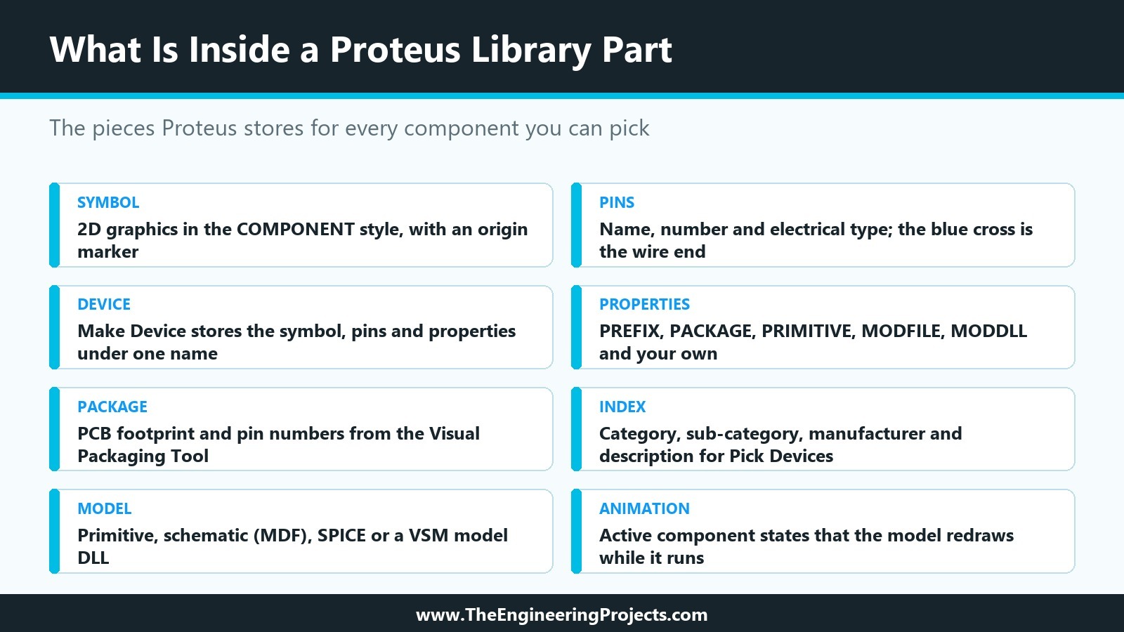
Everything here is based on Proteus 8.5 Professional and the help files that come with it, and on the libraries we build at The Engineering Projects, such as the HC-12 wireless module whose library file we open later on. Where Labcenter, the maker of Proteus, keeps details under a non-disclosure agreement, we say so instead of guessing. The picture below shows the pieces of a library part at a glance.
What Is a Proteus Library?
Proteus uses two words that are easy to mix up. A device is a type of real-world part, such as an NPN transistor, a PIC microcontroller or an HC-12 module. A component is one instance of a device placed on your schematic. When you pick the BC547 device and place it three times, you get three components, Q1, Q2 and Q3, all built from the same device. A library is a file that stores devices (or symbols, or PCB footprints) so that you can pick them again in any design.
The LIBRARY folder of a Proteus installation holds two symbol libraries and well over a hundred device libraries, together with a few support files. The help lists their extensions: library files (.LIB), index files (.IDX), 3D model files (.VML or .3DS), the master style file (.STY) and configuration files (.INI). On our Proteus 8.5 installation, the folder holds 148 .LIB files, our own libraries included.
When people talk about "a Proteus library" for a module, such as our SIM808 Library for Proteus, they usually mean a small set of files that belong together: a device library file (.LIB) with its index file (.IDX), a simulation model (in our case a .DLL file) and a demo project that shows the part working. Creating a Proteus library means creating exactly these files, and that is what this series is about.
The Three Kinds of Library Files in Proteus
Proteus keeps different kinds of objects in different libraries. You will meet all three in this series.
| Library type | What it holds | Supplied with Proteus | Your own (read/write) |
|---|---|---|---|
| Device library | Complete schematic parts: graphics, pins, properties, packaging and index data | Over a hundred, for example DEVICE.LIB, ACTIVE.LIB | USERDVC.LIB or a library you create |
| Symbol library | Graphics symbols, terminals, module ports and device pin symbols | SYSTEM.LIB | USERSYM.LIB |
| Package library | PCB footprints used by the PCB layout module | For example PACKAGE.LIB and the IPC-7351 libraries | USERPKG.LIB |
All three use the .LIB extension, but the files are not interchangeable. Each one begins with a short text that names its kind: when we looked into the files of our installation, DEVICE.LIB and ACTIVE.LIB begin with "DEVICE LIBRARY", SYSTEM.LIB with "SYMBOL LIBRARY" and PACKAGE.LIB with "PACKAGE LIBRARY". They are binary files, so you never edit them by hand; Proteus and its Library Manager do that for you.
Symbol libraries are more interesting than they look. Terminals, module ports and device pins are all symbols with a name prefix. When you select the Terminal mode and see DEFAULT, INPUT and OUTPUT, you are really using symbols called $TERDEFAULT, $TERINPUT and $TEROUTPUT from SYSTEM.LIB. Even the pins you place around a new part are symbols, so you can design your own pin shapes later.
Labcenter installs its own libraries as read-only and recommends keeping them that way: the update system replaces them with new versions, and anything you saved into them would be lost. Only USERDVC.LIB, USERPKG.LIB and USERSYM.LIB are installed read/write, for your own devices, footprints and symbols, and you can create further libraries with the Library Manager. One rule from the help deserves to be repeated: never remove items from SYSTEM.LIB.
What Is Inside a Proteus Component?
Every device in a library is built from the same pieces. Knowing them now will make each of the coming tutorials feel familiar.
The Symbol, or Device Body
The device body is the complete drawing of the part, apart from its reference text and pins. For a simple chip it is just a box, drawn with the 2D graphics tools in the COMPONENT graphics style. For a transistor, an op-amp or a realistic module board, you combine lines, boxes, circles, arcs, paths and text. A graphic that follows the COMPONENT style changes when the style changes; a graphic with local, fixed settings (for example a body that is always filled black) keeps its look. Short lines that should look like part of a pin are drawn in the PIN style. An Origin marker sets the point by which the part is placed; without one, Proteus uses the end of the top left pin.
The Pins
Pins are special device pin objects placed around the body. The blue cross at one end of a pin is its connection point, where wires attach; the other end should touch the body. Every pin carries a name, a number and an electrical type. The electrical type is used by the electrical rules check and by the simulator, and for digital simulation models it must be right.
| Pin type | Type ID | Typical use |
|---|---|---|
| Passive | PS | Terminals of passive parts |
| Input | IP | Analogue or digital inputs |
| Output | OP | Analogue or digital outputs |
| Bidirectional | IO | Data bus pins of processors and memories |
| Tri-state | TS | ROM output pins |
| Pull-down | PD | Open collector or open drain outputs |
| Pull-up | PU | Open emitter or open source outputs |
| Power | PP | Power and ground pins |
Two pin rules surprise many beginners. First, pins with the same name are treated as connected, in the netlist and on the PCB, which is useful for several GND pins but dangerous by accident. Second, a hidden pin (one whose body is not drawn) is connected automatically to the net of the same name, so a hidden VCC pin joins the VCC net. A name written as RD/$WR$ shows an overbar on WR.
The Device Properties
Once the body and pins are drawn and tagged, the Make Device command turns them into a device. It is a wizard with several pages: the device properties (the device name and the reference prefix, such as U or R, plus the Active Component settings for animation), the packaging, the component properties and their definitions, the datasheet and help file, and finally the library selection, where you also set the category, sub-category and notes. We will walk through every page in its own tutorial.
The Package
A device that will go on a PCB needs a footprint and a map from pin names to pad numbers. The Visual Packaging Tool creates this map, and one device can carry several packagings with different numbers: a PIC16F877 can be offered as DIL40 and as PLCC44. The same tool handles multi-element parts. A 7400 has four identical gates in one package, and the reference suffix chooses the pin numbers, so the gate labelled U1:C uses pins 8, 9 and 10. A part that only exists for simulation, like many animated modules, can be made without any package.
The Index
Each device also carries index data: a category (CAT), a sub-category (SUBCAT), a manufacturer (MFR) and a description (DESC). The Pick Devices dialogue, which opens with the P key, uses it when you search: your keywords are matched against part names, descriptions, categories and sub-categories, and all keywords must match. The index data lives in the .IDX file next to the library. The index file of our HC-12 library, for example, is only 267 bytes long; it starts with the text "DEVICE LIBRARY INDEX" and holds the category Peripherals, the sub-category Wireless, the manufacturer name and the description. That small file is why our module appears when you type "HC-12" into Pick Devices.
How Properties Connect a Part to Its Simulation Model
A drawing alone does not simulate. Proteus decides what a part does in a simulation by reading its properties, and there are four kinds of model it can use.
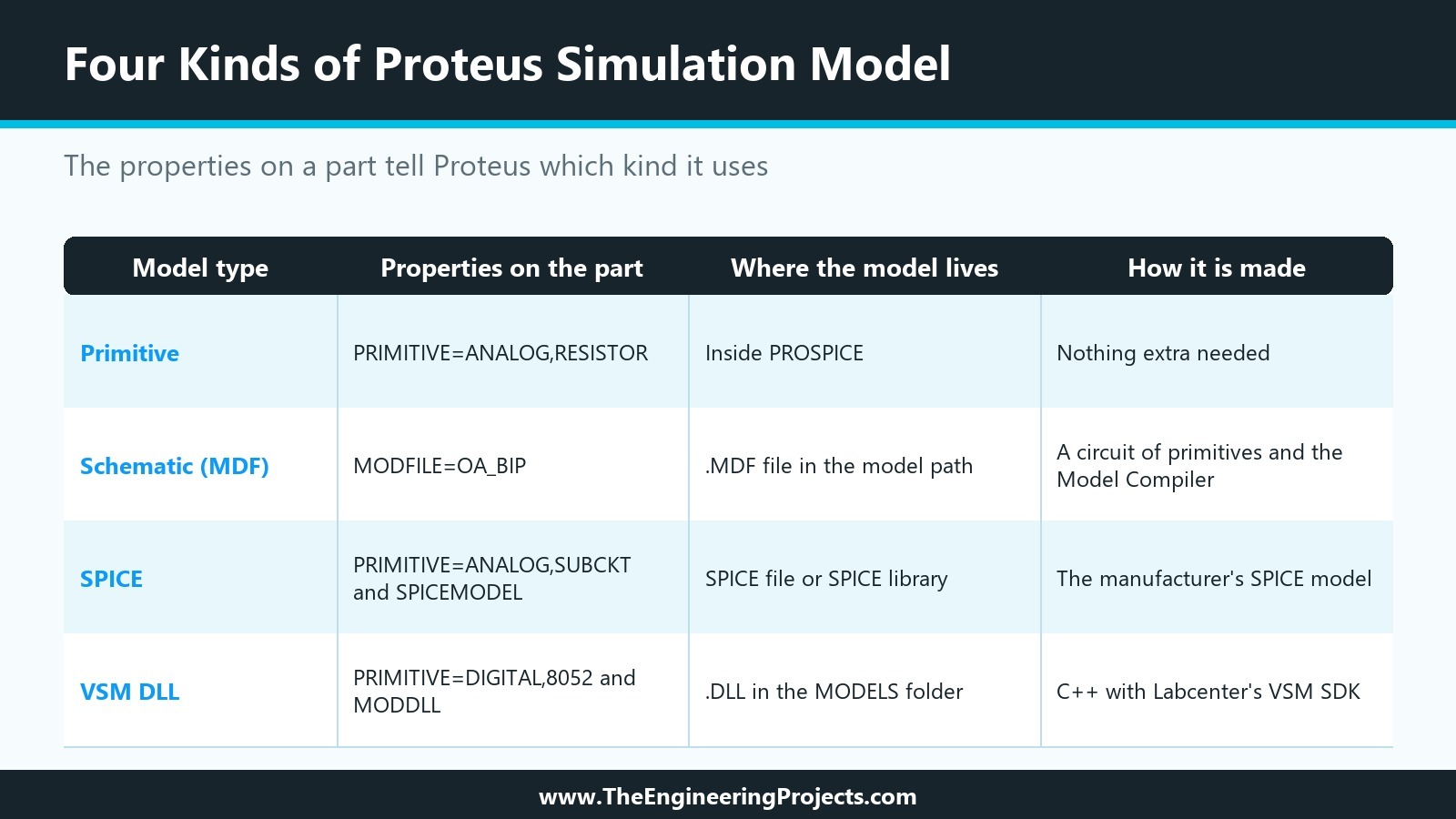
- Primitive models are built into PROSPICE, the Proteus simulator. Resistors, capacitors, diodes, transistors, gates, counters, latches and memories are primitives. A resistor carries the property
PRIMITIVE=ANALOG,RESISTORand needs no other file. The standard primitives are in the ASIMMDLS and DSIMMDLS libraries. - Schematic models are circuits of primitives drawn in Proteus and compiled into an MDF file. The part points to its model with
MODFILE; the 741 op-amp, for example, hasMODFILE=OA_BIP. One MDF file can model several devices through a parameter mapping table. - SPICE models come from component manufacturers. A subcircuit model has properties such as
PRIMITIVE=ANALOG,SUBCKTandSPICEMODEL=CA3140, and the model text is kept in a file named bySPICEFILEor in a SPICE library named bySPICELIB. - VSM models are primitives implemented in an external DLL instead of inside PROSPICE. They carry both
PRIMITIVEandMODDLL; the 8052 microcontroller, for example, hasPRIMITIVE=DIGITAL,8052andMODDLL=MCS8051. One DLL can implement several parts, and a VSM model can also drive the animation of its part.
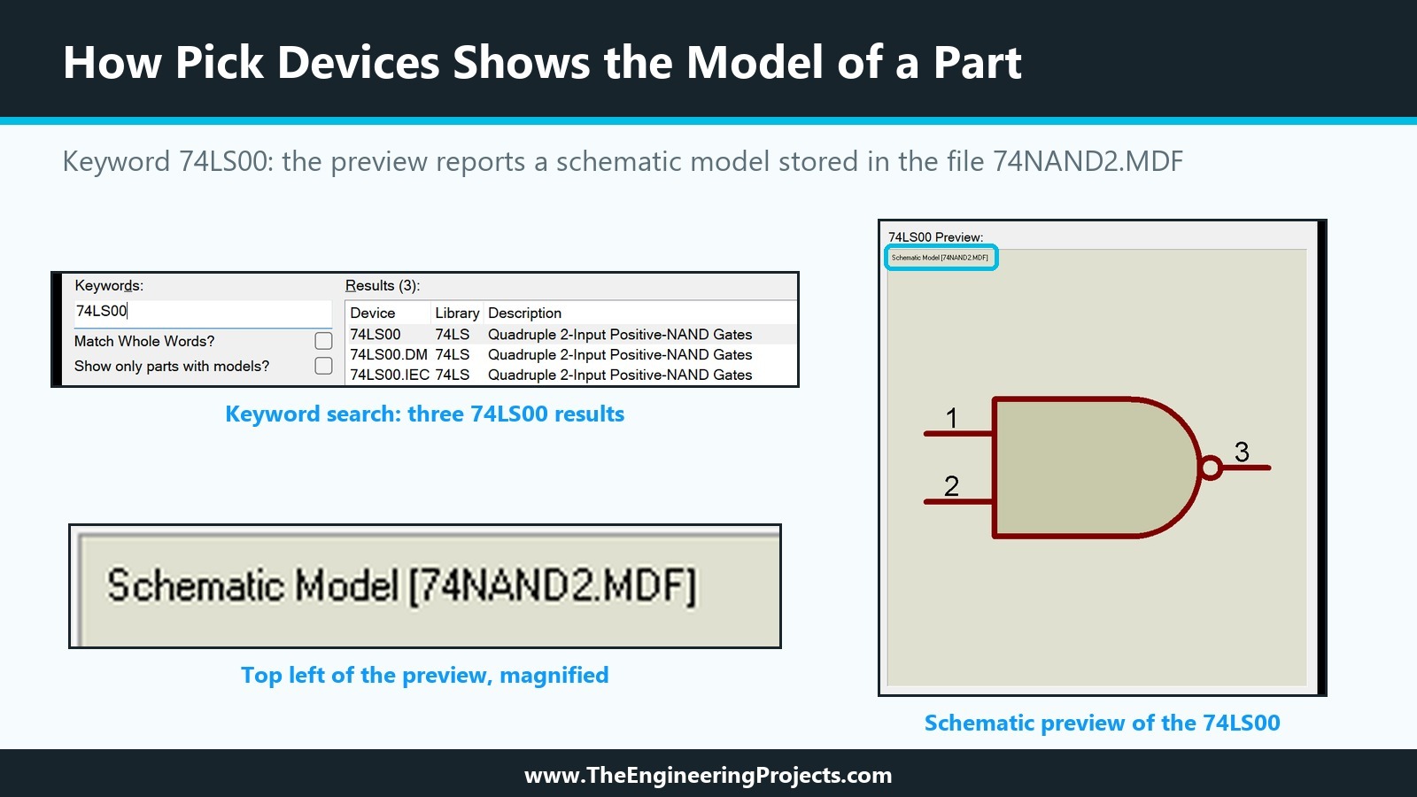
You can see which kind of model a part uses before you place it: Pick Devices shows the model type at the top left of its preview, for example "Schematic Model [74NAND2.MDF]" for the 74LS00, as the picture below shows. A part without a model is still perfectly useful for schematics and PCBs; the Proteus help points out that expecting a model for every part, down to large processors, would be unrealistic. If such a part ends up in a simulation and has no effect on it, like a connector, you give it PRIMITIVE=NULL and the simulator ignores it.
Most of our own libraries, and the Traffic Light Module of this series, use the last kind: a VSM model in a DLL. It is the only kind that can model a complete module with its own behaviour, its own messages and its own animated graphics.
A Real Example: The Script Inside Our HC-12 Library
When you decompose a device in Proteus (break it back into graphics and pins), you also get a text script with its name, prefix, packaging and default properties. The same script is stored inside the library file. Below is the script stored in TEPHC12.LIB, the library of our HC-12 433 MHz wireless serial module, exactly as it appears in the file.
{*DEVICE}
{PREFIX=U}
{ACTIVE=HC12TEP,0,DLL}
{*PROPDEFS}
{NAME="NAME",READONLY STRING}
{VERSION="VERSION",READONLY STRING}
{DES="Designed by",READONLY STRING}
{PRIMITIVE="Primitive Type",HIDDEN STRING}
{MODDLL="VSM Model DLL",HIDDEN STRING}
{BAUD="Stored baud rate (1200-115200)",FLOAT,1200,115200}
{FORMAT="Stored serial format (8N1, 8O1, 8E1, 8N2...)",STRING}
{CHANNEL="Stored channel (1-127)",FLOAT,1,127}
{MODE="Stored mode FU (1-4)",FLOAT,1,4}
{POWER="Stored power P (1-8 = -1 to +20 dBm)",FLOAT,1,8}
{STATE="Active state",HIDDEN STRING}
{*INDEX}
{CAT=Peripherals}
{SUBCAT=Wireless}
{MFR=The Engineering Projects}
{DESC=HC-12 433 MHz Wireless Serial Port Module - transparent 433 MHz serial link with SET pin, AT commands, FU1-FU4 and link budget; talks to every TEP HC-12 in the design}
{*COMPONENT}
{NAME=HC-12 433 MHz Wireless Serial Port Module}
{VERSION=1.0}
{DES=www.TheEngineeringProjects.com}
{PRIMITIVE=DIGITAL,HC12TEP}
{MODDLL=TEPHC12.DLL}
{BAUD=9600}
{FORMAT=8N1}
{CHANNEL=1}
{MODE=3}
{POWER=8}
{STATE=-1}
The Four Sections of a Device Script
The script is easy to read once you know its four sections.
{*DEVICE}holds the device settings: the reference prefix U, so the first module becomes U1, and the lineACTIVE=HC12TEP,0,DLL. That line carries the Active Component settings of the Make Device wizard: the symbol name stem HC12TEP, the number of states (none here) and the link to a model DLL. Our HC-12 does not use stored state symbols, because its DLL draws the animated antenna waves and the control panel itself.{*PROPDEFS}holds the property definitions: the text shown in the Edit Component dialogue, the type and the limits.CHANNELis a number from 1 to 127,FORMATis free text, andPRIMITIVE,MODDLLandSTATEare hidden, so they do not clutter the Edit Component dialogue and are not changed by accident.{*INDEX}holds the index data that Pick Devices searches: category, sub-category, manufacturer and description.{*COMPONENT}holds the default values that every new component receives.PRIMITIVE=DIGITAL,HC12TEPtells the simulator that this is a digital primitive called HC12TEP, andMODDLL=TEPHC12.DLLnames the file that implements it.BAUD=9600,CHANNEL=1and the other values are the module's settings at the start of a simulation, which users can change per component.
This is the whole link between a drawing and its behaviour: two properties name a primitive and a DLL, and the DLL brings the part to life. When we build the Traffic Light Module, its script will look much the same, only shorter.
What Happens When You Press Run?
Between pressing Run and seeing the first animation, Proteus goes through several stages. The help describes them for graph-based simulation, and the same model rules apply to an interactive simulation.
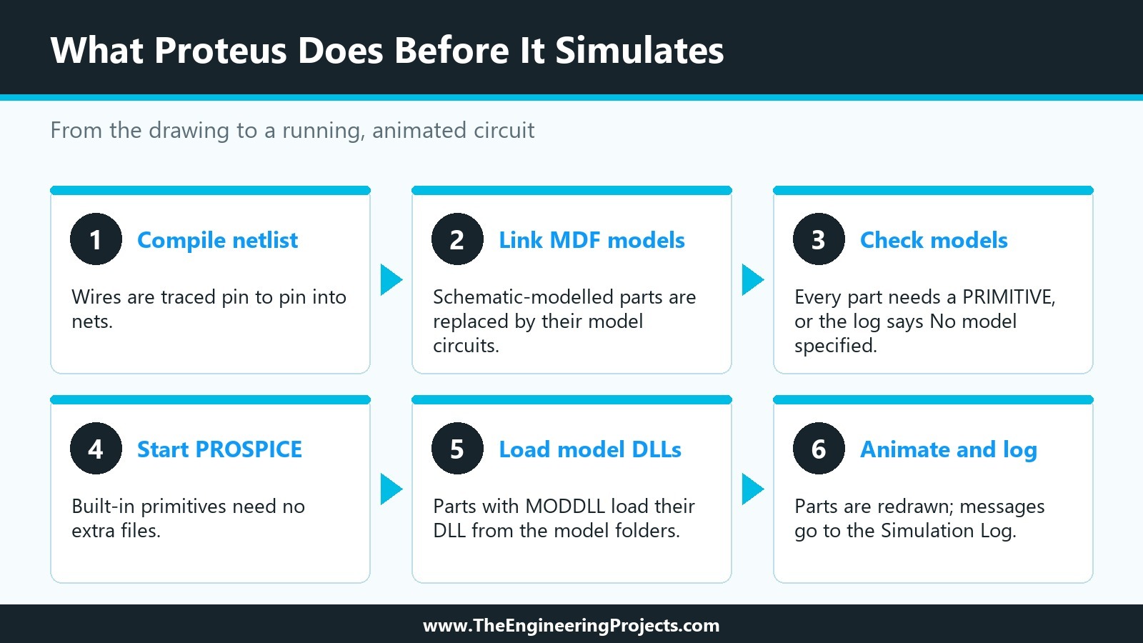
- Netlist compilation. Proteus traces the wires from pin to pin and builds a list of components and nets.
- Netlist linking. Parts with a schematic model are replaced by the circuit in their MDF file, with the model's inputs and outputs connected where the part's pins were. After this step, every part left in the netlist should have a
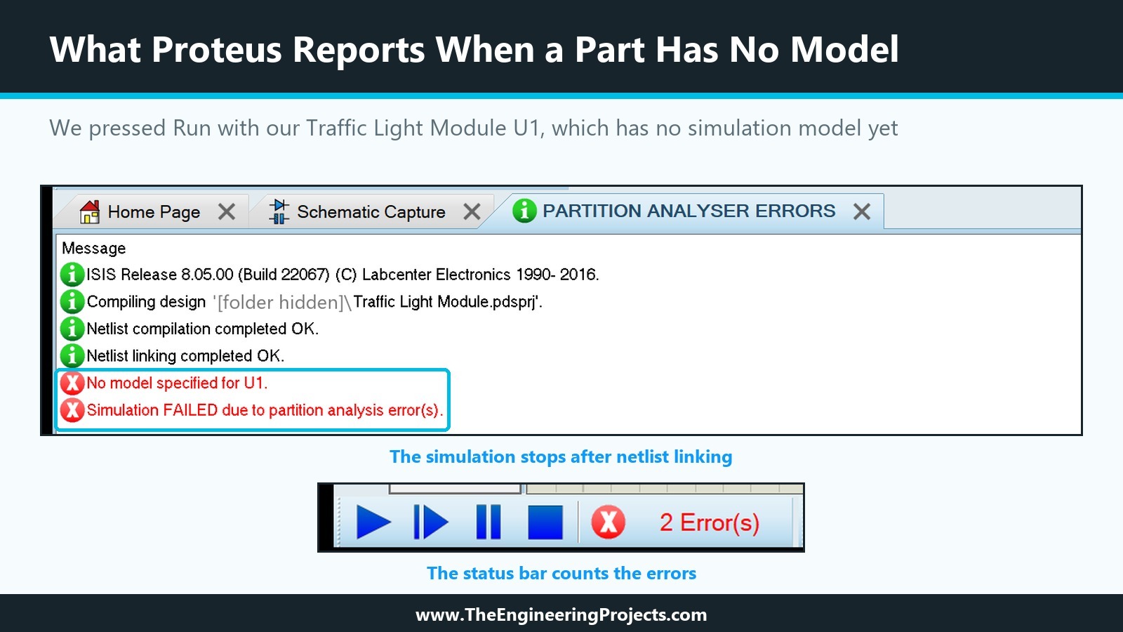
PRIMITIVEproperty. - Checking the models. During the partition analysis, a part with neither a primitive nor a model file stops the simulation. In Proteus 8.5, the message reads
No model specified for U1., followed by "Simulation FAILED due to partition analysis error(s)." - Partitioning. For graphs, Proteus works out which parts of the circuit must be simulated and in which order, and reuses earlier results where nothing changed.
- Simulation. PROSPICE simulates the circuit. Built-in primitives need no files; a VSM model is loaded from the DLL named in its
MODDLLproperty. - Animation and logging. Animated parts are redrawn as their states change, and every message from the simulator and from the models is written to the Simulation Log.
You can watch the first stages yourself. Our Traffic Light Module, which we build in this series, has no simulation model yet, so we placed it and pressed Run. Proteus compiled and linked the netlist without complaint, then stopped at the model check, opened a tab called PARTITION ANALYSER ERRORS and showed the error count in the status bar:
The Simulation Log and Its Messages
The Simulation Log is your best friend when you create a library. Messages from a model are prefixed with the component reference in square brackets, so you can tell which part spoke. During an interactive simulation, the log opens from the Debug menu. Our own models write to it on purpose: the HC-12 model, for example, reports when it starts, when it is not powered, and when a packet arrives but is too weak to be received.
| Message | What it means | What to check |
|---|---|---|
| No model specified | The part has no PRIMITIVE or MODFILE property and sits in the simulated circuit | Add a model, or PRIMITIVE=NULL for parts that do not take part |
| Model DLL not found | The DLL named in MODDLL is not in the current folder or a model folder | Copy the DLL into the MODELS folder; check the name |
| Value not found in parameter mapping table | The MDF file exists but does not model this part value | Use a modelled value, or extend the MDF file |
| Unresolved module pin (warning) | The part has a pin that its schematic model does not have | Often harmless; check it if a new model does not work |
| Cannot open SPICE source file | The file named in SPICEMODEL or SPICEFILE cannot be found | Put the file in the design folder or the model path |
How Does Animation Work in Proteus?
Animated parts are what make Proteus fun: LEDs glow, switches flip, LCDs show text. Proteus calls them Active Components, and their settings sit on the first page of the Make Device wizard.
The Active Component Settings
- Symbol Name Stem is the start of the names of the symbols that show the part's states. The symbols are named after the stem, an underscore and a number.
- No. of States is the number of states, and normally the number of state symbols you draw.
- Bitwise States is for parts made of several elements that are each on or off. Each element then needs an off and an on symbol, named STEM_N_0 and STEM_N_1, so the number of symbols doubles. Three independent lamps are a typical case.
- Link to DLL says whether a VSM model DLL drives the part.
Clickable Parts and Hot Spots
Clickable parts use two special markers, INCREMENT and DECREMENT, which define hot spots on the drawing: a click on them raises or lowers the part's state. Hot spots of this kind are what let you operate a part with the mouse while the simulation runs. A VSM model can go further and draw its own graphics while the simulation runs. The LCD models of Proteus work this way, and so do the antenna waves, phones and control panels of our module libraries.
One honest note: Labcenter provides the full details of Active Components only on a limited basis, under a non-disclosure agreement, as part of its VSM SDK. In the animation tutorials of this series, we will show what you can see and test in Proteus itself and in our own model code, and we will tell you where the SDK is needed.
Where Does Proteus Look for Library and Model Files?
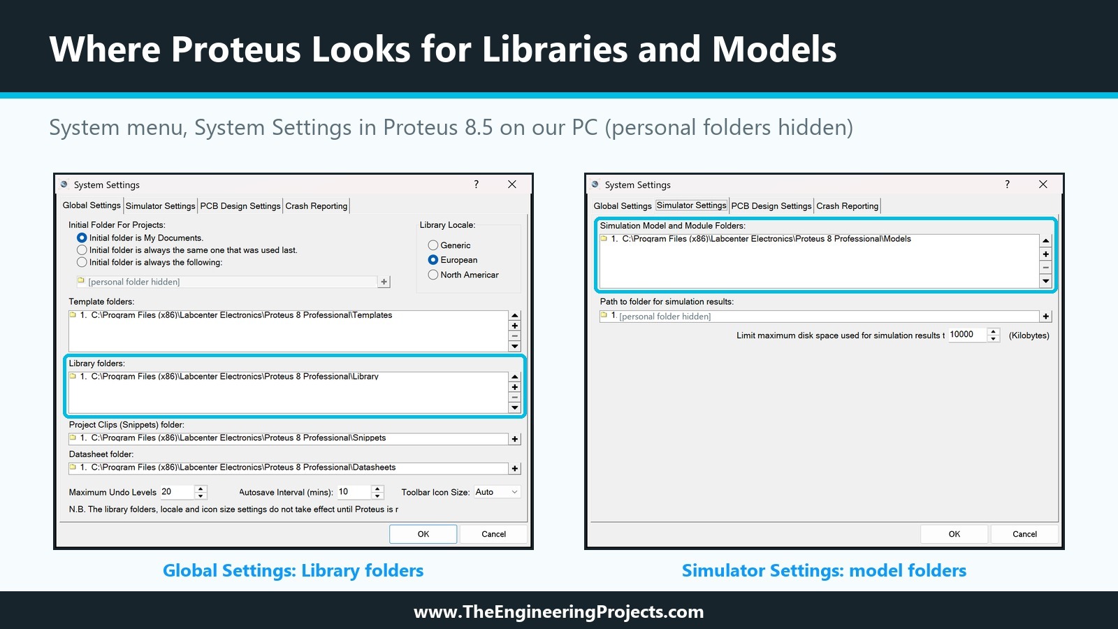
Proteus finds libraries and models through folder lists that you can see and change in System Settings on the System menu of the schematic editor. (Some help pages call this dialogue Set Paths.)
- Library folders, on the Global Settings tab, are where Proteus looks for .LIB files. According to the help, the installer puts the LIBRARY folder in the ProgramData branch; on our installation of Proteus 8.5, the tab shows the Library folder inside the Proteus folder under Program Files (x86). Always check the dialogue on your own PC before copying files. The dialogue also notes that a change of the library folders takes effect only after Proteus is restarted.
- Simulation Model and Module Folders, on the Simulator Settings tab, are where Proteus looks for model files (MDF, SPICE and DLL) before a simulation. On our installation, this is the Models folder next to the Library folder. You can add a folder of your own here if you want to keep your models apart from Labcenter's.
Two Warnings About Library Folders
Two warnings from the help are worth knowing early. If you use several library folders, no file name may appear in two of them, or nobody will know which one was loaded. And a library folder on a network must be fully read/write for every user, or Proteus will not work.
How to Install Someone Else's Library
Installing someone else's library follows directly from this. Our download packages ask you to close Proteus, copy the .LIB and .IDX files into the library folder and the model DLL into the models folder, and then start Proteus again. After that, the part appears in Pick Devices under its category, and the demo project runs. Our tutorial How to Add New Library in Proteus 8 shows this installation step by step.
Why Your Design Keeps Its Own Copy of Every Part
This point confuses many people the first time they edit a library part. A Proteus design file carries its own copies of the library parts it uses. If you change a part in a library, designs that already use it do not change. To bring the new version into a design, you pick the part again: when you pick a device that is already loaded into the schematic, Proteus updates it from the library on disk, matching pin positions or pin names so that the wiring stays connected. If two libraries contain a device with the same name, the Pick command loads the newer one, which is handy when you keep a modified copy of a Labcenter part in USERDVC.LIB.
Why Editing a Part Is Safe
The same idea makes editing safe. To change a part, you place it, tag it and use Decompose, which breaks it into graphics, pins and the property script we saw above. You edit the pieces and run Make Device again; if you tag the script as well, the properties come back without retyping. Proteus then offers to update every component in the open design. The properties of components that are already placed are not changed, because Proteus cannot know which values were edited by hand.
The Library Manager in Short
The Library Manager copies, moves and deletes parts between libraries, creates new library files and deletes old ones. It shows a source library and a destination library side by side, and a read-only library can only be a source. The count at the bottom of each list shows how many items a library holds and how many index entries remain. Labcenter warns that the Library Manager keeps no backups and has no undo, and recommends backing up your own libraries weekly and before any change. We will create our own library file with it in a later tutorial.
The Complete Workflow: From an Idea to a Shared Proteus Library
Putting it all together, creating a Proteus library follows the same path every time, and this series follows it step by step with the Traffic Light Module.
- Plan the component: size, pin order, colours and what it should do in a simulation.
- Draw the body with the 2D graphics tools and graphic styles, layer by layer.
- Place and annotate the pins: names, numbers and electrical types.
- Run Make Device: name, prefix, properties, index data and the target library.
- Create your own library file with the Library Manager.
- Add a PCB package if the part will be used on a board.
- Choose a simulation model: primitive, schematic, SPICE or a VSM DLL.
- Add animation and interactive controls.
- Test the part with an Arduino demo project and read the Simulation Log.
- Package the files with a README so that others can install them.
Newer Proteus releases add other ways to get parts. Labcenter's library page describes an automatic web search that imports parts from online part databases when the installed libraries have no match. Imported parts give you symbols and footprints; a simulation model for a new module is something you still have to create yourself, and that is where this series is heading.
What You Need for This Series
- Proteus 8 Professional. We use version 8.5, and every menu name in this series comes from it.
- A writable library. USERDVC.LIB is enough to start; later we create our own library file.
- Arduino IDE to build the HEX file of the demo sketch that drives the Traffic Light Module.
- For the DLL tutorials only: a C++ compiler such as Visual Studio and Labcenter's VSM SDK. The help in Proteus 8 says the SDK is supplied on request to Labcenter, with a signed non-disclosure agreement and a valid update service contract.
In the Next Tutorial
Now that you know the mechanism behind a Proteus library, we can start building one. In the next tutorial, How to Design a New Component in Proteus, we will plan the Traffic Light Module, decide its size, pin order and colours on the Proteus grid, and see how its drawing will be built up in layers before we draw the first line.
FAQ
What is the difference between a device and a component in Proteus?
A device is the part type stored in a library, such as the 74LS00. A component is one placed instance of a device on a schematic, such as U1 or U2. Many components can be built from one device.
What are the .LIB and .IDX files in Proteus?
The .LIB file stores the library objects: devices with their graphics, pins and properties, or symbols, or PCB footprints. The .IDX file stores the index data (category, sub-category, manufacturer and description) that Pick Devices searches.
Where is the library folder in Proteus 8?
It depends on the installation. Open System Settings on the System menu: the Library folders list on the Global Settings tab shows the folders Proteus uses for libraries, and the Simulation Model and Module Folders list on the Simulator Settings tab shows the folders for model files.
Why does Proteus say "No model specified"?
A part in the simulated circuit has no PRIMITIVE or MODFILE property, so the simulator does not know what it does. Use a part that has a model, add a model to your own part, or give a part that does not matter for the simulation, such as a connector, the property PRIMITIVE=NULL.
Can I edit the library parts supplied with Proteus?
Labcenter's libraries are read-only and are replaced by updates. Save your modified copy in USERDVC.LIB or in a library of your own; when two devices have the same name, the Pick command loads the newer one.
Do I need programming to create a Proteus library?
No, not for the symbol, pins, properties, packaging, schematic models or SPICE models. Programming is needed for a VSM model DLL, which is written in C++ with Labcenter's VSM SDK and is what makes a module like our HC-12 behave like the real one.
That is all for today. We now know what a Proteus library is made of and how Proteus uses it from Pick Devices to the Simulation Log. If you have any questions, ask in the comments. In the next tutorial, we will start designing our Traffic Light Module. Take care.
Comments
0