


How to Create a Schematic Simulation Model (MDF) in Proteus


Hello friends, I hope you are doing well. This is the fourteenth tutorial in our series on how to create a Proteus library. In the previous tutorial, How to Add a SPICE Model in Proteus, we gave our Traffic Light Module its first working model: a SPICE subcircuit with a resistor and an LED per lamp, linked to the part with four properties. Today, we build the same behaviour a different way, by drawing it. Our topic is how to create a schematic simulation model (MDF) in Proteus.
We will look inside two of Labcenter's own schematic models, draw the model of our module in a project of its own, compile it with the Model Compiler into an MDF file, attach it to our part with the MODFILE property and test it. On the way, we read the compiled file and find two mistakes before running a single simulation. Finally, we use the feature that makes schematic models worth the effort: properties of the part that flow into the model, so that each placed module can have its own resistor values.
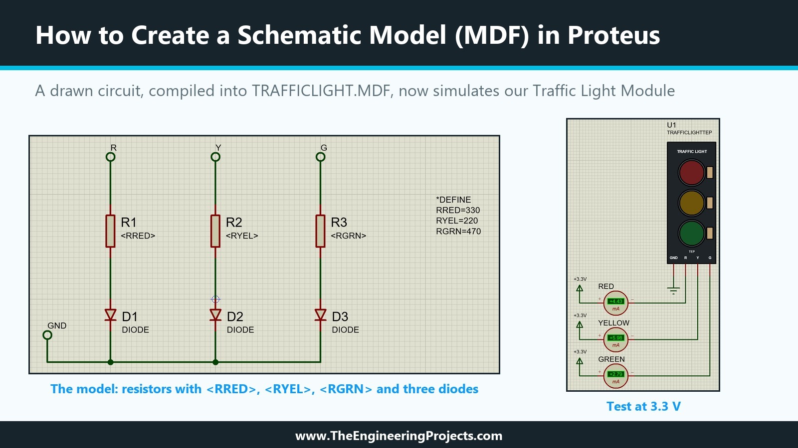
Everything here was done in Proteus 8.5 Professional on our PC, and every current in this tutorial was read from the simulation. The picture below shows the result: on the left, the model circuit as we drew it; on the right, our part using the compiled model in the test circuit from the previous tutorial.
What Is a Schematic Model in Proteus?
A schematic model is a circuit drawn in Proteus that describes how a part behaves. The help explains the idea: when a device is too complex for a single primitive, you draw a circuit of simulator primitives that mimics it. The circuit can be the real internal electronics, but more often it uses ideal sources and switches, because they simulate faster. A part points to its schematic model with the MODFILE property, which Labcenter makes read only by convention.
The drawing is not used directly. The Model Compiler turns it into a model file with the extension .MDF, and that file is what PROSPICE reads when the simulation starts. The help adds that further details of the process are in the VSM SDK documentation; on our PC, the installed VSM SDK help only explains how to request the SDK from Labcenter. Everything in this tutorial therefore comes from the general help, from Labcenter's own model files and from our own tests.
What Is Inside an MDF File?
An MDF file is plain text. Its first line reads LISA MODEL DESCRIPTION FORMAT 8.0, followed by the name of the design it was compiled from and four sections:
- *PROPERTIES: default values for properties the model uses.
- *MODELDEFS: named parameter sets for primitives, which the help describes for *MODELS script blocks; often empty.
- *PARTLIST: one line per part in the model, with its primitive and properties.
- *NETLIST: the connections. A net that carries the marker GT is a connection to the outside world, one of the pins of the part that uses the model.
Before we added ours, our Models folder held nine loose .MDF files, such as TURTLE.MDF, and 32 model libraries with the extension .LML. A model library simply holds many MDF texts in one file; ACTIVE.LML on our PC contains 41 of them, from ACIMETER to WMETER.
Two Labcenter Models as Examples
Reading Labcenter's models is the best way to learn what is possible. Two of them in ACTIVE.LML are worth a closer look.
LEDA, the Model of the Animated LED
In the twelfth tutorial, we saw that LED-RED uses the schematic model LEDA. Its MDF text shows how it works: a *PROPERTIES section with defaults such as VF=1.5 and IMAX=10mA, a series resistor whose value is <RS>, two voltage-controlled switches that turn on at <VF> and at the breakdown voltage, and a real-time current probe, RTIPROBE, with MAX=<IMAX>. The names in angle brackets are filled in from the part: LED-RED carries VF=2.2V, which, by the rule described below, replaces the default of 1.5 V in its model. The current probe is what lights the LED on the screen, and it is the subject of the next tutorial.
DCIMETER, the Model of the DC Ammeter
The DC ammeters we used in the last two tutorials have a schematic model too. With Edit all properties as text, our RED ammeter shows MODFILE=DCIMETER, MODDLL=READOUT for the display, and STATE=3, which is what the Display Range Milliamps stores. The DCIMETER text in ACTIVE.LML contains a current probe with SCALE=<SCALE> and a *MAPPINGS table on STATE that picks one of four scale factors; for STATE 3, it is 1000, which turns amps into milliamps. This is how one model serves all display ranges. The help describes the same mechanism for logic gates: a table placed on the model sheet selects timing values according to the value of the part, so that one gate model can serve the 7400, the 74LS00 and the 74S00.
What a Schematic Model Can Do That Our SPICE Model Cannot
Our SPICE subcircuit from the previous tutorial has its resistor values written into the file. A schematic model can take them from the part instead. The help explains the rule: a child sheet, and a model is one, inherits the properties of its parent object as sheet properties, and a property expression such as <RRED> in the model picks them up. If the same name is also defined on the model sheet, the value of the parent wins, so the model's own definitions act as defaults.
That gives our module something useful: boards from different makers use different resistors, and with a schematic model, each placed module can be set to match its board. A schematic model can also mix analogue and digital primitives and contain the real-time probes that drive animation, which we need for the lamps later.
How to Create a Schematic Model in Proteus: Step by Step
Creating the model and attaching it to our part took six steps: a new project for the model, the drawing, the defaults, compiling, checking the compiled file, and Make Device on our part.
Step 1: Start a Separate Project for the Model
The Model Compiler compiles the open design, so the model needs a project of its own; our test project, with its meters and terminals, would not do. We used File, New Project, named the project TRAFFICLIGHT and saved it in the same folder as our test project. In the wizard, we created a schematic from the DEFAULT template, no PCB layout and no firmware project.
The name matters more than it seems. When the Model Compiler saves the model, it proposes the name of the design as the file name, so a project called TRAFFICLIGHT becomes TRAFFICLIGHT.MDF without any typing.
Step 2: Draw the Model Circuit
The model is the same circuit as our SPICE subcircuit, drawn instead of written. You can see it on the left of the first picture.
Terminals for the Pins
Each pin of our part becomes a terminal in the model. We placed four DEFAULT terminals from the Terminals mode and labelled them R, Y, G and GND, exactly like the pins of TRAFFICLIGHTTEP. When a terminal is selected, the status bar reads Type=GT, the same marker that the MDF file uses for its outside connections.
Resistors with Property Names as Values
We placed three generic resistors, RES from the DEVICE library, and typed <RRED>, <RYEL> and <RGRN> into their Resistance fields instead of numbers. The schematic shows these names under the resistors; the numbers arrive only when the model is used.
Diodes with the LED Parameters
For the LEDs, we used the analogue diode primitive DIODE from the ASIMMDLS library, labelled Analogue Primitive [DIODE] in Pick Devices. It is the SPICE3F5 diode model, so it accepts the same IS, N and RS parameters as our .MODEL lines: 4E-13, 1E-13 and 3E-14 for IS, with N=3 and RS=10 for all three. Its Edit Component dialogue offers Saturation Current, Ohmic Resistance and Junction Capacitance under Advanced Properties, but not N, so we entered all four properties with the tick box Edit all properties as text, one property in braces per line, for example {IS=4E-13} and {N=3}.
Step 3: Give the Properties Their Defaults
If a placed part does not set RRED, the model still needs a value. We placed a script block with the Text Script mode and typed four lines: *DEFINE, then RRED=330, RYEL=220 and RGRN=470. In the Edit Script Block dialogue, Enter starts a new line; the help gives Ctrl+Enter as the shortcut for OK. These definitions become the *PROPERTIES section of the MDF file.
Step 4: Compile the Model with the Model Compiler
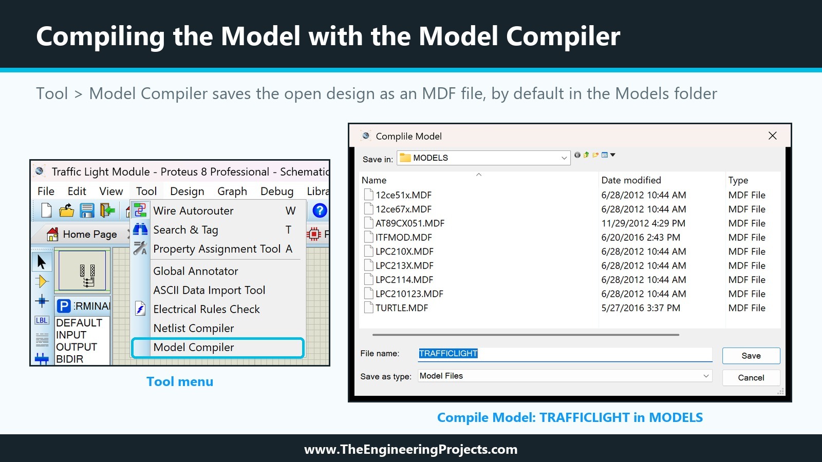
With the project saved, we chose Tool, Model Compiler. A dialogue titled Compile Model opened in the MODELS folder of the installation, with TRAFFICLIGHT already in the file name field and Model Files as the type. Save wrote TRAFFICLIGHT.MDF into the Models folder, which is exactly where PROSPICE looks for model files.
Step 5: Read the MDF File Before You Use It
Because an MDF file is text, you can open it in Notepad and check the model before simulating. Our first compiled file was 788 bytes long, and it showed two mistakes.
Mistake 1: The Diodes Were Upside Down
The netlist connected the bottom of R1 to pin K of D1 and the GND terminal to pin A: every LED pointed the wrong way. Unrotated, the DIODE symbol has its anode at the bottom, and we had placed it as if the anode were at the top. We deleted the three diodes, which also removed their wires, placed them again rotated by 180 degrees and wired them anew. In the simulation, reversed LEDs would simply have drawn almost no current; in the MDF file, the mistake was visible at a glance.
Mistake 2: Properties on One Line Became One Value
In the second compile, the part list read IS=4E-13N=3RS=10PRIMITIVE=ANALOGUE for D1, one property with a nonsense value. We had typed {IS=4E-13}{N=3}{RS=10}{PRIMITIVE=ANALOGUE} on a single line. On separate lines, Proteus stores four properties. In the first compile, D3, also typed on one line, had kept only IS=3E-14.
The Final Model File
After both fixes, the third compile produced this file of 817 bytes:
LISA MODEL DESCRIPTION FORMAT 8.0
=================================
Design:   TRAFFICLIGHT.pdsprj
Doc. no.: <NONE>
Revision: <NONE>
Author:   <NONE>
Created:  10/1/2026
Modified: 10/1/2026

*PROPERTIES,3
RGRN=470
RRED=330
RYEL=220

*MODELDEFS,0

*PARTLIST,6
D1,DIODE,DIODE,IS=4E-13,N=3,PRIMITIVE=ANALOGUE,RS=10
D2,DIODE,DIODE,IS=1E-13,N=3,PRIMITIVE=ANALOGUE,RS=10
D3,DIODE,DIODE,IS=3E-14,N=3,PRIMITIVE=ANALOGUE,RS=10
R1,RES,<RRED>,PRIMITIVE=ANALOG,PRIMTYPE=RESISTOR
R2,RES,<RYEL>,PRIMITIVE=ANALOG,PRIMTYPE=RESISTOR
R3,RES,<RGRN>,PRIMITIVE=ANALOG,PRIMTYPE=RESISTOR

*NETLIST,7
#00001,2
R1,PS,2
D1,PS,A

#00003,2
R2,PS,2
D2,PS,A

#00005,2
R3,PS,2
D3,PS,A

R,2
R,GT
R1,PS,1

Y,2
Y,GT
R2,PS,1

G,2
G,GT
R3,PS,1

GND,4
GND,GT
D3,PS,K
D2,PS,K
D1,PS,K
Everything is where it should be. The *PROPERTIES section holds the three defaults from our script block. The part list shows the diodes with all four properties and the resistors with <RRED>, <RYEL> and <RGRN> as values; RES itself is the same primitive as before, PRIMITIVE=ANALOG with PRIMTYPE=RESISTOR. The netlist connects each resistor to the anode of its diode, the nets R, Y, G and GND carry the GT marker, and the GND net joins the three cathodes. The model contains no pin numbers at all: the outside connections are matched by name, which is why the terminals must be named exactly like the pins of the part.
Step 6: Attach the Model with Make Device
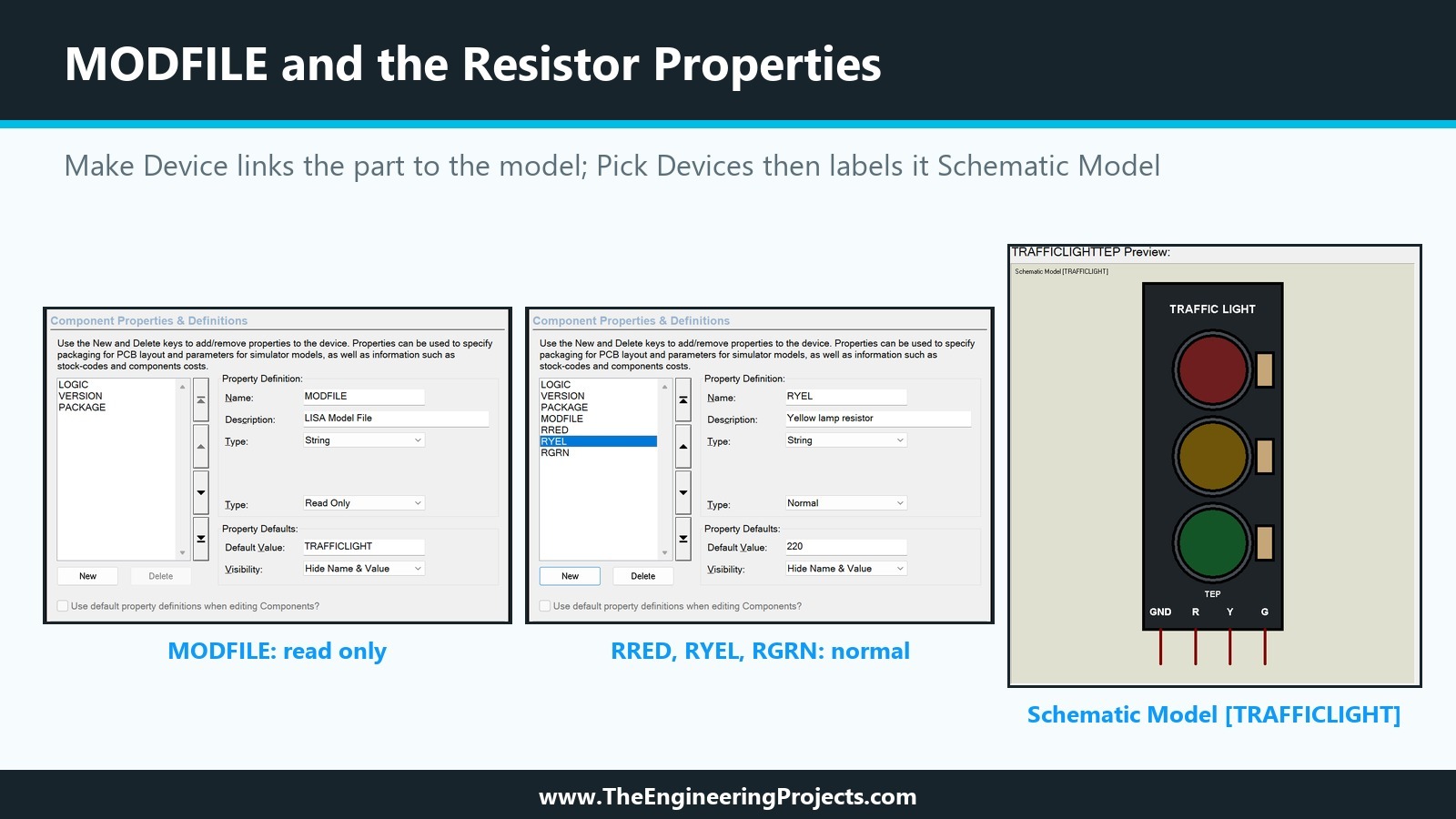
Back in our test project, we opened Make Device on U1, as in the previous tutorial, and changed the properties on the Component Properties and Definitions page:
- We deleted PRIMITIVE, SPICEMODEL, SPICEFILE and SPICEPINS. A part should point to one model only.
- We added MODFILE from the New list. Proteus filled in the description LISA Model File and the type Read Only, and we typed TRAFFICLIGHT as the default, the name of the model without the extension.
- We added three blank properties, RRED, RYEL and RGRN, with the descriptions Red lamp resistor, Yellow lamp resistor and Green lamp resistor, the type String, the behaviour Normal, and 330, 220 and 470 as defaults.
- We raised VERSION from 1.2 to 1.3.
We stored the part in TEPTUTORIAL as before, replaced the existing device and updated all instances. TEPTUTORIAL.LIB grew from 31,042 to 35,628 bytes. These are the property lines it now holds:
; TRAFFICLIGHTTEP version 1.3, read from TEPTUTORIAL.LIB after Make Device
{*PROPDEFS}
{LOGIC="Lamps light when the pin is",HILOW}
{VERSION="Library version",READONLY STRING}
{PACKAGE="PCB Package",PACKAGE,1,TRAFFICLIGHT-TEP}
{MODFILE="LISA Model File",READONLY STRING}
{RRED="Red lamp resistor",STRING}
{RYEL="Yellow lamp resistor",STRING}
{RGRN="Green lamp resistor",STRING}
{*COMPONENT}
{LOGIC=1}
{VERSION=1.3}
{PACKAGE=TRAFFICLIGHT-TEP}
{MODFILE=TRAFFICLIGHT}
{RRED=330}
{RYEL=220}
{RGRN=470}
We chose String rather than a numeric type for the resistor properties so that a user can type a value the way Proteus users usually do; in our test, 1k worked as well as 1000. In Pick Devices, the label at the top left of the preview now reads Schematic Model [TRAFFICLIGHT].
How to Test the Schematic Model
We kept the test circuit of the previous tutorial: three DC ammeters in milliamps between +3.3V terminals and the pins R, Y and G, and a ground terminal on GND.
The Same Currents as the SPICE Model
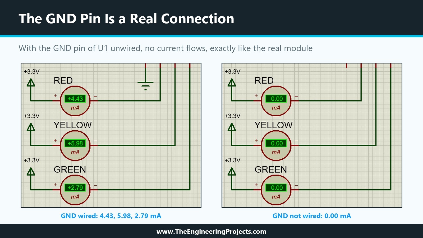
After Run, the ammeters showed 4.43 mA for red, 5.98 mA for yellow and 2.79 mA for green, exactly the values the SPICE model gave in the previous tutorial at 3.3 V. That is the expected result, because the circuit and the diode parameters are the same and both are simulated by the same SPICE engine. It is also a good habit: when you rebuild a model in a new form, compare it with the old one before you change anything else.
Changing a Property on the Placed Part
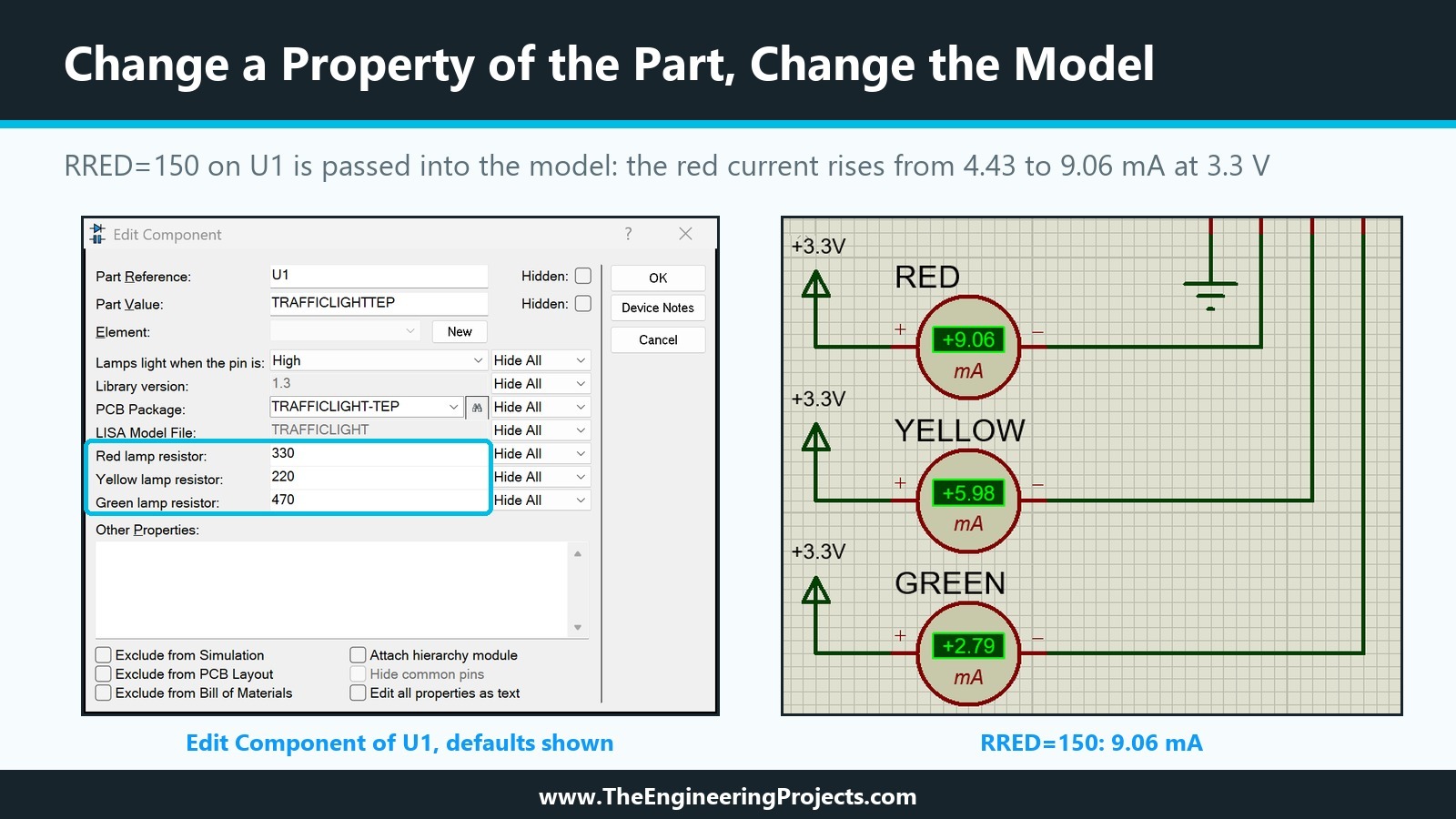
Now the new feature. In the Edit Component dialogue of U1, the three resistor properties appear under their descriptions, next to Library version 1.3 and the read-only LISA Model File. We changed Red lamp resistor from 330 to 150, as for a board with a smaller resistor, and ran the simulation again. The red current rose from 4.43 mA to 9.06 mA, while yellow and green stayed at 5.98 and 2.79 mA. Our own calculation with the LED parameters gives 9.06 mA for 150 ohm at 3.3 V, so the value really travelled from the part into the model. With 1k, the red current fell to 1.57 mA, again as calculated. Afterwards, we set it back to 330.
Testing the GND Connection
In the previous tutorial, we gave GND its own node so that the model would only work when the GND pin is wired. We checked the same for the schematic model: we deleted the ground terminal of U1 and pressed Run. All three ammeters showed 0.00 mA, and the simulation ran without an error message, just as a real module without ground would stay dark without complaining. After Undo, the currents returned. The GND terminal of the model is a real connection to the GND pin, not a hidden link to the ground of the circuit.
Where to Keep MDF Files
Like a SPICE file, an MDF file must be in one of the folders listed under Simulation Model and Module Folders in System Settings, which on our installation is the Models folder; the Model Compiler saved it there by default. Keep the model project, TRAFFICLIGHT.pdsprj, next to your library sources, because the MDF file cannot be turned back into a drawing: every change starts in the project and ends with a new compile.
The SPICE files of the previous tutorial, TRAFFICLIGHT.CIR and TEPTUTORIAL.SML, are still in our Models folder, but version 1.3 of the part no longer refers to them. When we package the library at the end of the series, only the files the part actually uses will go into it.
Parameter Mapping Tables: One Model for Several Parts
We did not need a mapping table for our module, but it is the other big advantage of schematic models, and the help gives the syntax. A script block that starts with *MAP ON VALUE, followed by lines such as 74LS00 : TDLH=10n,TDHL=6n, defines sheet properties according to the value of the part that uses the model. The primitives in the model then use <TDLH> and <TDHL>, and a DEFAULT line covers values that are not listed. When a part's value is missing from the table and there is no default, the simulation stops with the message we met in the twelfth tutorial: the value was not found in the parameter mapping table.
For our module, a mapping table could serve several board variants from one model, for example a value per maker with its own resistor set. The per-part properties we used are simpler, though, and let users enter any value.
Common Mistakes When Creating a Schematic Model in Proteus
| Problem | Cause | Solution |
|---|---|---|
| The MDF contains the test circuit too | The model was compiled from the test project | Draw the model in a project of its own |
| Almost no current through the LEDs | Diodes placed the wrong way round | Check A and K in the netlist of the MDF |
| A property with a strange value | Several properties typed on one line | One {NAME=value} per line, then check the MDF |
| A pin is not connected to the model | The terminal name differs from the pin name | Name each terminal exactly like its pin |
| Changes in the drawing have no effect | The part still uses the old MDF | Compile again after every change |
| The model ignores a placed part's value | The model uses a number instead of <NAME> | Use <NAME> in the model and define NAME on the part |
In the Next Tutorial
Our part now has a schematic model with adjustable resistors, and the lamps still stay dark. In the next tutorial, How to Create an Animated Component in Proteus, we finally make them light up: we draw the on and off states of the three lamps, declare them in Make Device, and add real-time probes to our model, the same kind of probe that drives Labcenter's LED.
FAQ
What is an MDF file in Proteus?
A schematic model compiled into text by the Model Compiler. It lists the model's parts, its connections and the default values of its properties. Parts use it through the MODFILE property.
How do I create an MDF model in Proteus?
Draw the model circuit in a project of its own, with terminals named like the pins of your part, then choose Tool, Model Compiler and save the file in the Models folder. Add MODFILE with the model name to the part in Make Device.
How do I pass a value from a part into its schematic model?
Give the part a property, for example RRED=330, and use <RRED> as a value inside the model. Define a default with a *DEFINE script block on the model sheet; the value on the placed part takes priority.
Can I edit an MDF file directly?
It is plain text, so you can read it, and reading it is a good way to find mistakes. Make your changes in the model project and compile again, though, so that the drawing and the file stay the same.
What is the difference between a schematic model and a SPICE model in Proteus?
A SPICE model is a netlist in SPICE syntax, usually from a manufacturer. A schematic model is drawn in Proteus and can use the part's properties, mapping tables, digital primitives and the real-time probes that animate parts.
That is all for today. Our Traffic Light Module now runs on a model we drew ourselves, and each placed module can match its own board. If you have any questions, ask in the comments. Take care.
Comments
0