


NEO-6M Library for Proteus V1.1 (GPS Module + Arduino)


Hello friends, I hope you all are doing great. Today, I am going to share the new NEO-6M GPS Library for Proteus V1.1. The u-blox NEO-6M is the GPS module most students start with: it is cheap, it talks to an Arduino over two wires, and it tells you where you are, how fast you move and the exact time. With this NEO-6M Library for Proteus, you can build and test your GPS project on your PC, without waiting next to a window for a satellite fix.
In this new version, you get two devices in one library: NEO-6M Simple, which draws a GPS screen on the schematic, and NEO-6M Advance, which opens a pop-up window with the GPS screen and four real GPS test tools (time to first fix, accuracy, NMEA check and route). I am also sharing a complete Arduino GPS Proteus simulation: one UNO prints the raw NMEA sentences, and the other reads the position with the popular TinyGPS++ library.
NOTICE: This library is very close to our hearts. Our GPS model does not just replay a recorded file: it moves 30 satellites over the sky, measures their signals, computes the fix and the HDOP from their geometry and answers the real u-blox commands, right inside Proteus. It took our team a lot of hard work, many test runs and many design changes, and this library is a tribute to that effort. Your feedback is the fuel that keeps us going, so please tell us what you think in the comments below or in the Proteus Libraries category of our forum. And if our free libraries help you in your studies or work, you can buy us a coffee (our donation page is coming soon). So, let's get started with the NEO-6M Library for Proteus:
What is the NEO-6M GPS Module?
The NEO-6M is a GPS receiver module made by u-blox. Most people buy it on the small blue GY-NEO6MV2 breakout board with a square ceramic patch antenna on a short cable. The receiver listens to the GPS satellites on 1575.42 MHz (the number printed on our patch), works out its position, and sends the result to your microcontroller as lines of text over a UART (the two-wire TX / RX serial port) at 9600 baud.
Besides the module, the breakout board carries a voltage regulator, a PPS LED, a small ML1220 backup cell and a 24C32 EEPROM for the settings. It is used in:
- GPS trackers and data loggers for cars, bikes and parcels,
- drones, robots and RC models that need to know where they are,
- clocks that take the exact UTC time from the satellites,
- student projects such as speedometers and "find my bag" devices.
GPS Terms You Will See in This Article
A GPS screen is full of short words. Here is what they mean:
| Term | Meaning |
|---|---|
| Fix | The receiver knows its position. A 2D fix (3 satellites) has no altitude; a 3D fix (4 or more satellites) has latitude, longitude and altitude. |
| TTFF | Time To First Fix: how long the receiver needs after power-up or a restart |
| Cold / warm / hot start | A restart that forgets everything / some / nothing about the satellites. A hot start is the fastest. |
| C/N0 (dB-Hz) | The signal strength of one satellite. Higher is better. |
| Satellites used / in view | Satellites in the fix / satellites above the horizon |
| HDOP, PDOP | "Dilution of precision": how good the satellite geometry is. About 1 is very good; larger numbers mean a less accurate position. |
| PPS | Pulse per second: the board's LED blinks once a second while there is a fix |
What are NMEA Sentences?
The NEO-6M reports everything as NMEA sentences: text lines that start with $GP, hold values separated by commas and end with * and a two-digit checksum. Every second, the module sends these six sentences:
| Sentence | What it carries |
|---|---|
| $GPRMC | The "recommended minimum": time, status (A = valid, V = no fix), position, speed in knots, course, date |
| $GPVTG | Course and speed over the ground, in knots and km/h |
| $GPGGA | Fix data: time, position, fix quality, satellites used, HDOP, altitude, geoid separation |
| $GPGSA | 2D or 3D fix, the satellites used, PDOP / HDOP / VDOP |
| $GPGSV | Satellites in view: number, elevation, azimuth and signal (four per sentence) |
| $GPGLL | Position and time |
| $GPTXT | Text messages, sent at start-up |
For example, this is one $GPGGA sentence from my simulation run:
$GPGGA,074303.00,5128.67267,N,00000.08962,W,1,09,1.00,45.9,M,45.4,M,,*71It says: at 07:43:03 UTC, the position is 51° 28.67267' north (51.477878°) and 0° 0.08962' west (0.001494°), fix quality 1 (a GPS fix), 9 satellites used, HDOP 1.00, altitude 45.9 m, geoid separation 45.4 m, and the checksum is 71. That is the Royal Observatory in Greenwich, the default home of our model.
What's New in NEO-6M Library for Proteus V1.1
- Two devices: NEO-6M Simple (
NEO6MTEP, GPS screen on the sheet) and NEO-6M Advance (NEO6MADVTEP, pop-up window), on one model (TEPNEO6M.DLL). - Close and reopen the Simple GPS screen: a red X on the screen, a PANEL button on the board.
- Board: a red PWR LED; the ceramic patch glows amber while acquiring and green with a fix; a SIMPLE / ADVANCE badge. The PPS LED still flashes once a second with a fix.
- Four GPS test tools in the Advance pop-up: TTFF, Accuracy, NMEA check and Route.
- TEP Serial Monitor in the demo instead of the Virtual Terminal. The second monitor also watches the GPS TX line, so you see the raw NMEA beside the TinyGPS++ output.
- Lighter package: about 1.5 MB, without the C++ source code.
NEO-6M Library for Proteus: Simple vs Advance
Both devices run the same GPS model; only the panel differs:
| Feature | Simple | Advance |
|---|---|---|
| Full NEO-6M model (NMEA, UBX commands, satellites, fix, HDOP) | ✔ | ✔ |
| PPS and PWR LEDs, glowing patch antenna, animated waves | ✔ | ✔ |
| GPS screen drawn on the schematic | ✔ | ✘ |
| GPS screen in a pop-up window you can move, resize and minimise | ✘ | ✔ |
| Location, motion, sky and cold start buttons | ✔ | ✔ |
| TTFF test (cold, warm and hot starts) | ✘ | ✔ |
| Accuracy test with CEP and 2DRMS | ✘ | ✔ |
| NMEA check and UBX configuration | ✘ | ✔ |
| Route test (walk or drive) | ✘ | ✔ |
| TEP Dark / Light theme, text size, Help page with Copy diagnostics | ✘ | ✔ |
| Same device name as v1.0 (old designs keep working) | ✔ | ✘ |
Pick Simple when you want to see the GPS screen on the sheet beside your circuit, and Advance when the sheet is crowded or you want to test your GPS code. The demo uses both.
Download NEO-6M Library for Proteus
Click the button below to download NEO-6M-GPS-Library-for-Proteus-v1.1.zip:
Download NEO-6M GPS Library for Proteus V1.1- README.txt: a detailed guide to the files.
- Proteus Library Files:
TEPNEO6M.LIB(both devices),TEPSERIALMON.LIBand our Arduino UNO libraryArduinoV3TEP.LIB/ArduinoV3TEP.IDX. - Proteus Model Files:
TEPNEO6M.DLLandTEPSERIALMON.DLL. - Proteus Simulation: the demo project, two .hex files and copies of both DLLs.
- Arduino Code: the two demo sketches, TinyGPS++ 1.0.3a (LGPL-2.1 licence) and AltSoftSerial 1.4 (MIT licence).
If you don't have Proteus yet, read How to Download and Install Proteus 7 and 8. New to libraries? Follow How to Install a New Library in Proteus.
How to Install NEO-6M Library for Proteus
- Close Proteus and extract the whole zip file.
- Copy the four files from Proteus Library Files into the LIBRARY folder, usually
C:\Program Files (x86)\Labcenter Electronics\Proteus 8 Professional\LIBRARY(on some PCsC:\ProgramData\Labcenter Electronics\Proteus 8 Professional\LIBRARY). - Copy
TEPNEO6M.DLLandTEPSERIALMON.DLLinto the MODELS folder. - Start Proteus, press P and search for NEO-6M. You get the Simple and the Advance device (category Peripherals > Wireless).
Updating from v1.0? Replace TEPNEO6M.LIB and TEPNEO6M.DLL, and delete any TEPNEO6M.IDX from the LIBRARY folder, or the parts list keeps showing the old device. The library was tested in Proteus 8.5; Proteus 7 is not supported.
NEO-6M GPS Module in Proteus
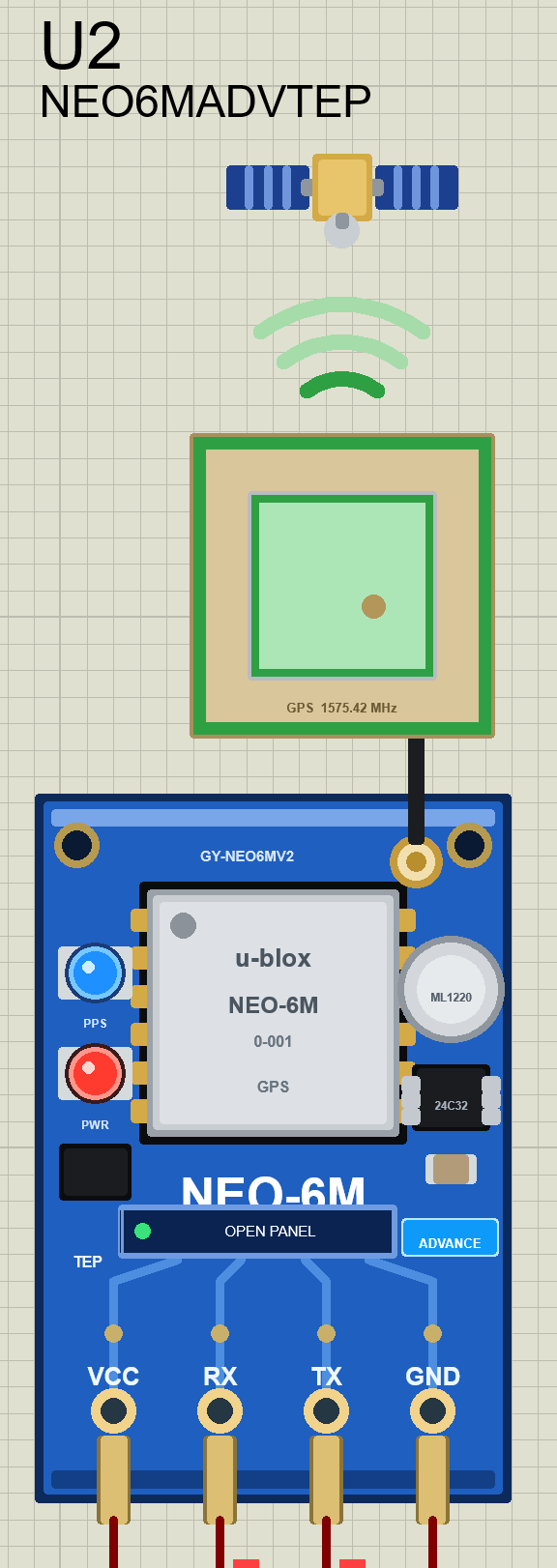
We designed the module as a clean TEP board in the blue of the real GY-NEO6MV2, with the u-blox module, the ML1220 cell, the 24C32 EEPROM, the PPS and PWR LEDs, and the ceramic patch antenna on its cable. A small satellite floats above the antenna. Here is the NEO-6M Advance in Proteus with a fix, caught at the moment its PPS LED flashed:
Pinout
The four pins are in the same order as on the real board:
| Pin | Function | Demo connection |
|---|---|---|
| VCC | Power supply | +5 V |
| RX | Serial input: UBX commands from the Arduino | Arduino D9 |
| TX | Serial output: NMEA sentences and UBX replies | Arduino D8 |
| GND | Ground | GND |
LEDs, Patch Antenna and Waves
| Indicator | What it shows |
|---|---|
| PPS LED | Flashes for 100 ms every second while there is a fix |
| PWR LED (red) | On while VCC and GND are powered |
| Patch antenna (amber, pulsing) | Satellites are tracked, but there is no fix yet |
| Patch antenna (green) | The module has a fix |
| Waves above the antenna | Green with a fix, amber while acquiring, grey without a signal |
The board button is PANEL on the Simple (green dot SHOWN, grey dot CLOSED) and OPEN PANEL on the Advance. The SIMPLE or ADVANCE badge tells you which device you placed.
Component Properties
Double-click the module to open Edit Properties. The properties are the same on Simple and Advance:
| Property | Meaning | Default |
|---|---|---|
| GPSLAT | Home latitude (degrees, + north) | 51.47788 |
| GPSLON | Home longitude (degrees, + east) | -0.00148 |
| GPSALT | Home altitude above sea level (m) | 46 |
| GPSGEOID | Home geoid separation (m) | 45.4 |
| GPSTTFF | Cold start time to first fix (s) | 10 (real module: 27) |
| GPSUTC | UTC at the start: PC or YYYY-MM-DD HH:MM:SS | PC |
| GPSBAUD | UART baud rate at power-up | 9600 |
Put your own city in GPSLAT / GPSLON, and the HOME button takes the module there. GPSTTFF is 10 s instead of the data sheet's 27 s, so your demos don't keep you waiting.
The GPS Screen: NEO-6M Simple
This is the part you will play with the most. Beside the Simple module, we have drawn a GPS screen that shows everything the receiver knows. Press Run, and for the first seconds the module is acquiring:
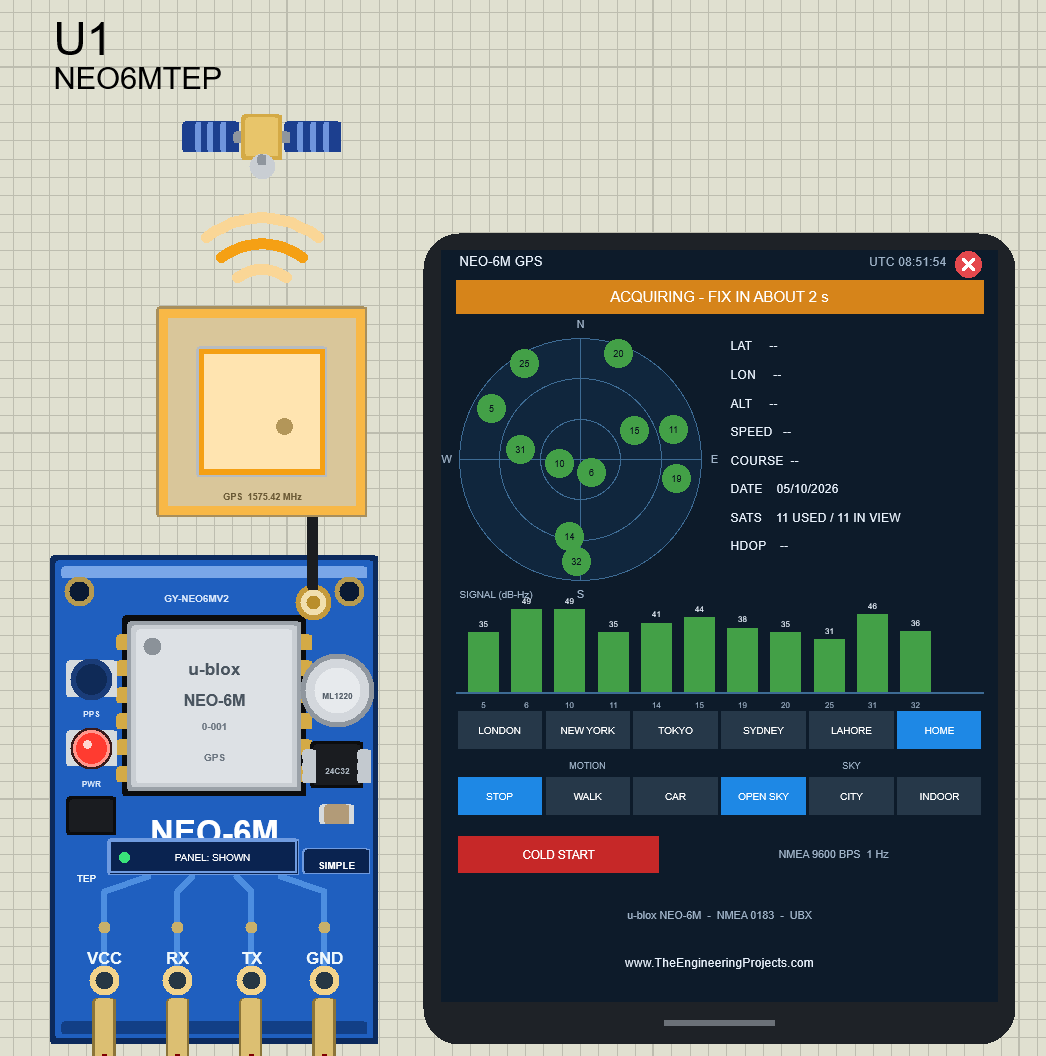
The banner says ACQUIRING - FIX IN ABOUT 2 s, the patch and the waves are amber, and the position fields are still empty ("--"). The sky plot and the signal bars already show the satellites, because the receiver hears them before it can compute a position. A few seconds later, the fix arrives:
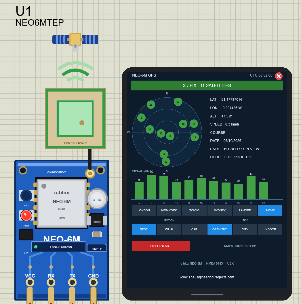
Every Part of the GPS Screen
| Part | What it shows |
|---|---|
| Banner | NO POWER, STARTING, SEARCHING FOR SATELLITES, ACQUIRING - FIX IN ABOUT n s, NO FIX - n OF m SATELLITES USABLE, NO SIGNAL - INDOOR, 2D FIX or 3D FIX - n SATELLITES |
| Sky plot | North is up. Green = used in the fix, amber = tracked but too weak for the fix, grey = in view with no signal |
| Data | LAT, LON, ALT, SPEED, COURSE, DATE, SATS (used / in view), HDOP and PDOP |
| Signal bars | C/N0 of every satellite in dB-Hz, with its number below |
| LOCATION | LONDON, NEW YORK, TOKYO, SYDNEY, LAHORE, HOME |
| MOTION | STOP, WALK (5 km/h on a 100 m circle), CAR (50 km/h on a 500 m circle) |
| SKY | OPEN SKY; CITY (buildings block satellites below 25°, 6 dB weaker); INDOOR (26 dB weaker) |
| COLD START | Clears everything; the next fix takes GPSTTFF |
| Red X | Closes the screen |
In this image, the module reports 51.477870 N, 0.001486 W, 47.5 m above sea level, 11 satellites used out of 11 in view, HDOP 0.76 and PDOP 1.30. That is an excellent fix, like a real receiver under an open sky.
Driving Through Tokyo
Now click TOKYO in the location row and CAR in the motion row. The module jumps to Tokyo and starts driving at 50 km/h on a 500 m circle:
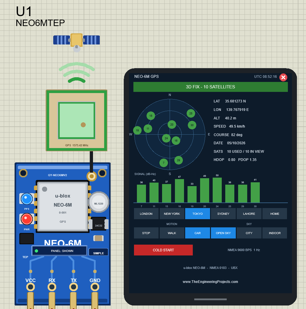
The screen shows 35.681273 N, 139.767919 E, a speed of 49.5 km/h and a course of 82° (heading east), with 10 satellites. The sky plot changed too, because Tokyo sees a different part of the sky. In the same moment, the Arduino receives these values in the NMEA sentences, so your sketch "drives" with the module.
Going Indoors
Click INDOOR. Every signal becomes 26 dB weaker, like inside a building. In my run, only three satellites stayed strong enough (20 dB-Hz or more), so the fix dropped to a 2D FIX - 3 SATELLITES: the altitude shows "-- (2D)" and the HDOP jumped to 3.90. Most of the time indoors, a real NEO-6M loses its fix completely, and so does our model.
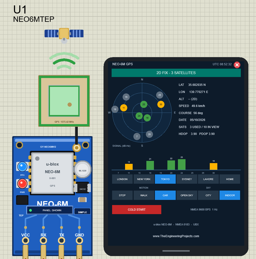
This teaches you one of the most important GPS lessons: a GPS antenna needs a view of the sky. Click OPEN SKY again, and the 3D fix comes back within a second or two.
Closing and Opening the GPS Screen
Need room on the sheet? Click the red X on the GPS screen. Only the board stays, and its button says PANEL: CLOSED with a grey dot. Click PANEL to bring the screen back. The module keeps working while the screen is closed.
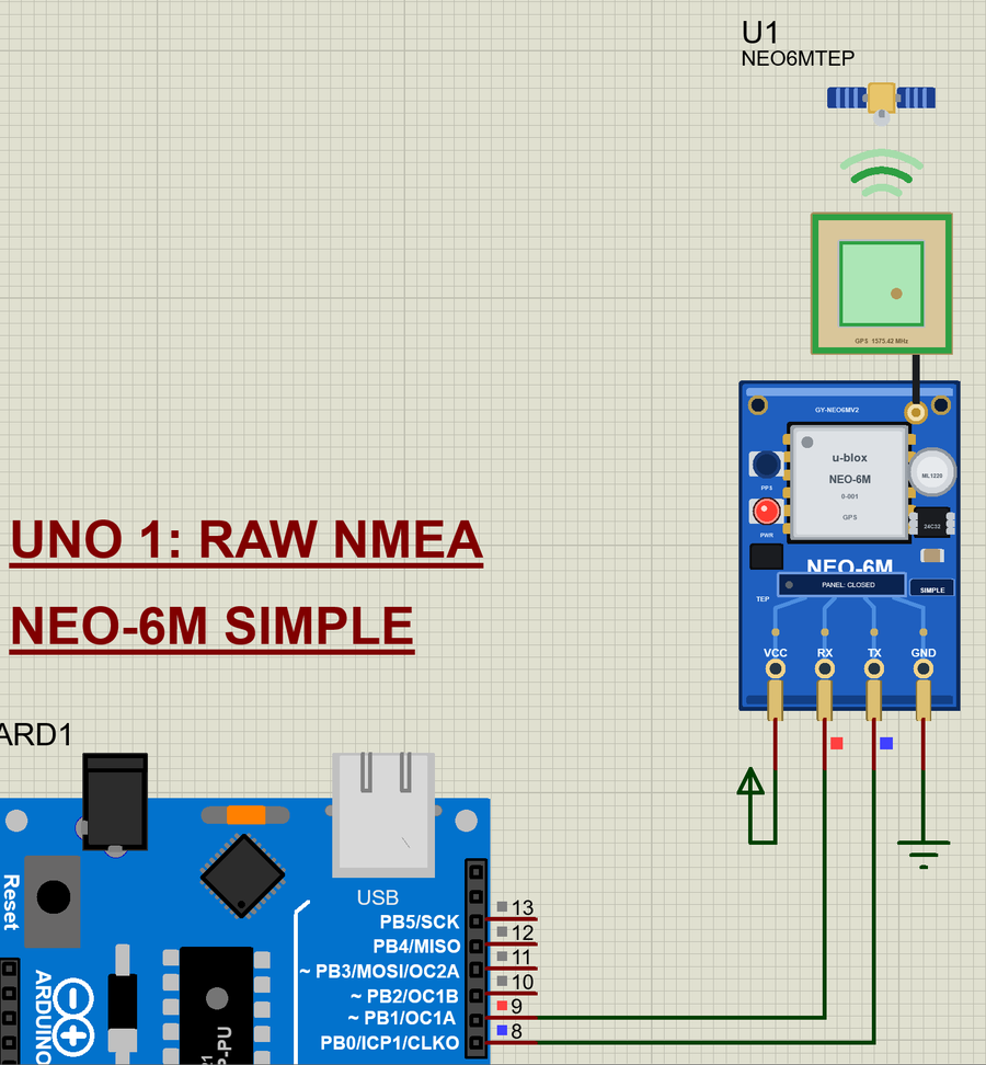
NEO-6M Advance: The Pop-Up Panel
The Advance device keeps only the board on the schematic. At Run, a TEP pop-up window opens with the look of our TEP Serial Monitor. Move it by its header, resize or minimise it, and reopen it with OPEN PANEL after you close it. The header shows the part and its state (for example U2 · 3D FIX), the tabs GPS and Test, and the theme, Settings (gear) and Help (?) icons.
The GPS Page
The GPS page is the same GPS screen, redrawn for a window: a big banner, the sky plot, a POSITION AND TIME card, the signal bars and the scenario buttons. Here it is a moment before the fix:
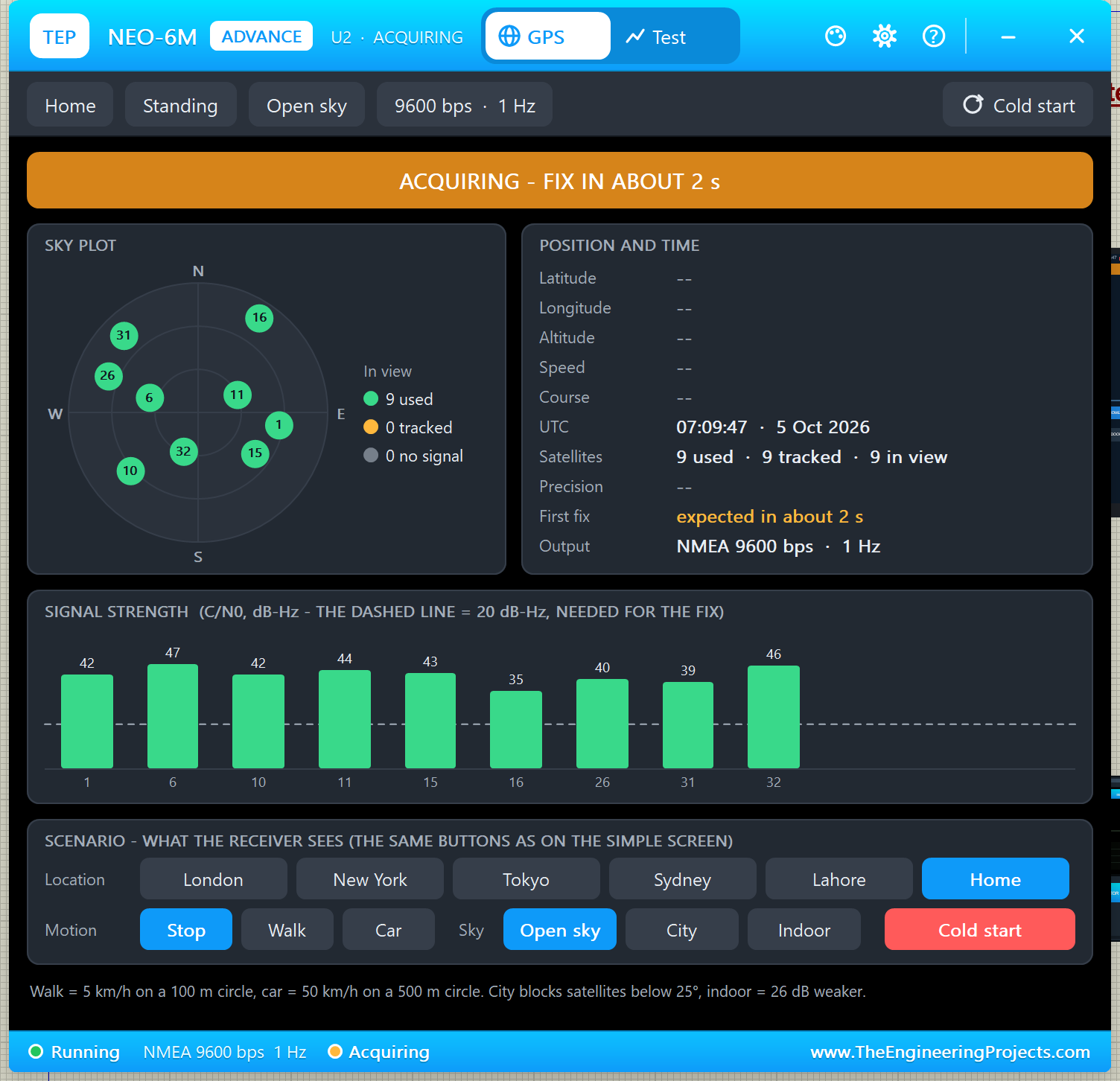
The toolbar chips show the scenario (Home, Standing, Open sky), the output (9600 bps · 1 Hz) and a Cold start button. The signal chart has a dashed line at 20 dB-Hz: a satellite needs at least that much to be used in the fix. After the fix:
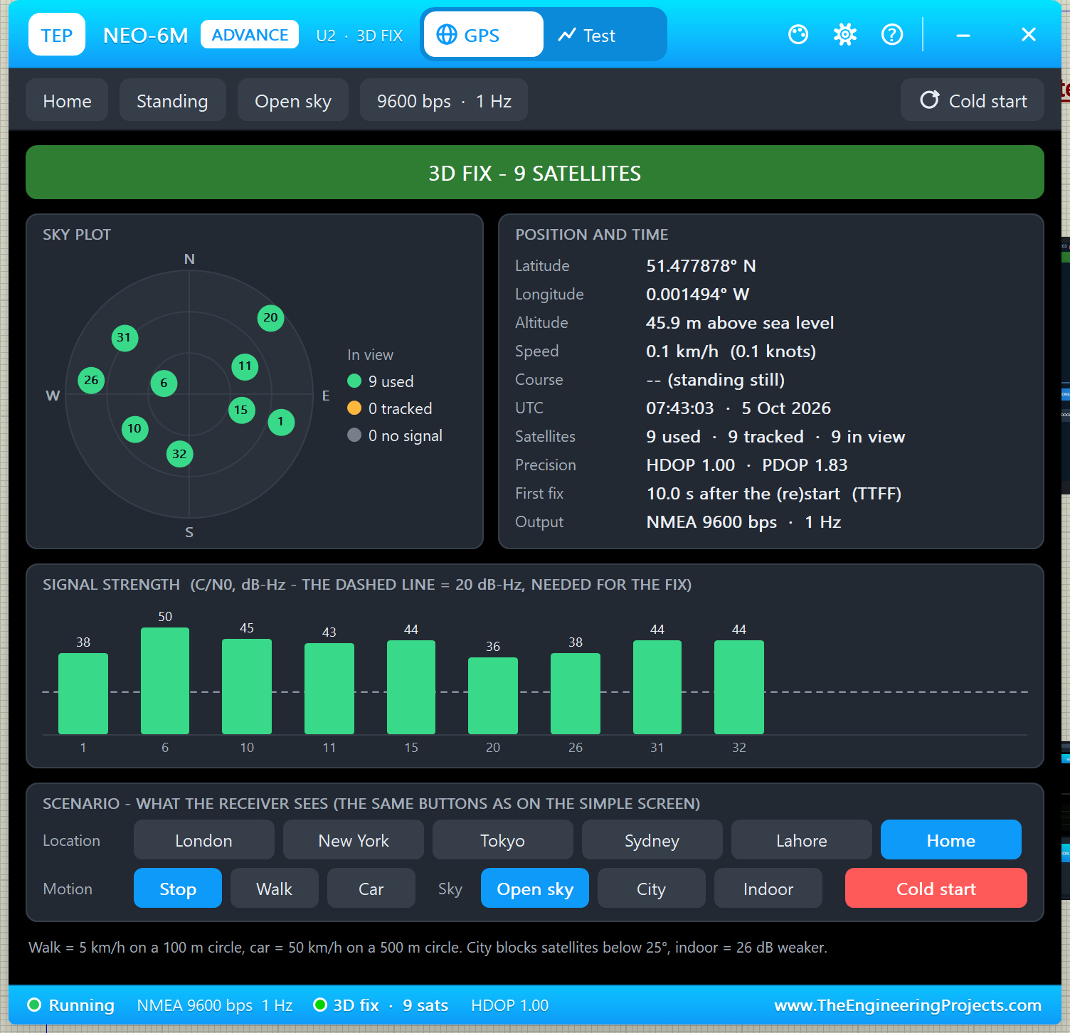
- Position: 51.477878° N, 0.001494° W, 45.9 m above sea level, 0.1 km/h (standing still).
- Satellites: 9 used · 9 tracked · 9 in view; HDOP 1.00 · PDOP 1.83.
- First fix: 10.0 s after the (re)start (TTFF), the value of GPSTTFF.
- Output: NMEA 9600 bps · 1 Hz.
The scenario buttons (Location, Motion, Sky and Cold start) work exactly like on the Simple screen.
The Test Page: GPS Test Tools
The Test page is what makes the Advance device special. It has four tools, and every number on it is measured on the running model, the same data your Arduino receives.
1. TTFF: Time to First Fix
Choose Cold, Warm or Hot, then 3, 5 or 10 runs, and click Run test. Each run really restarts the receiver, like the u-blox command CFG-RST, and times the first fix. Your sketch sees the fix drop and come back. Here is a cold start, three times:
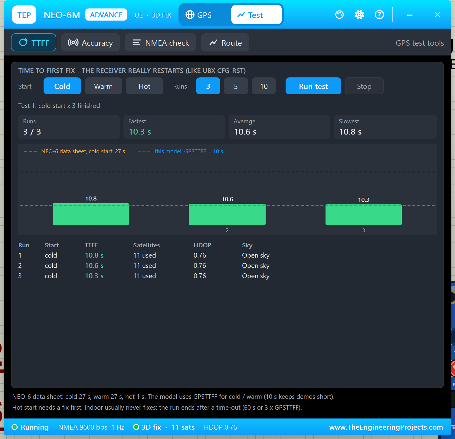
Each bar is one run, the blue dashed line is our model's GPSTTFF (10 s) and the amber one is the NEO-6 data sheet (27 s for a cold start). Now the same test with Hot, which keeps the satellite data:
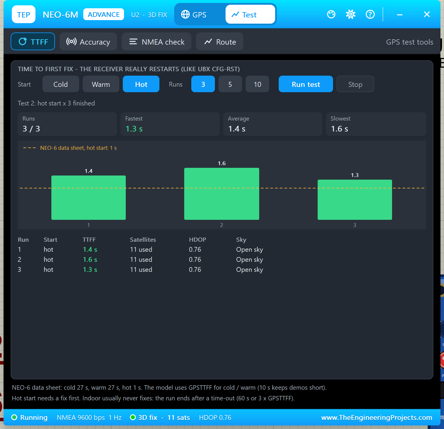
A hot start took only 1.3 to 1.6 s (data sheet: 1 s). Good for: testing how your sketch behaves while there is no fix, and understanding why a GPS that was switched off for a long time takes longer.
2. Accuracy
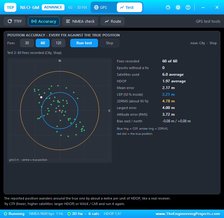
Choose 30, 60 or 120 fixes and click Run test. The tool compares every reported position with the true one and draws them on a scatter plot:
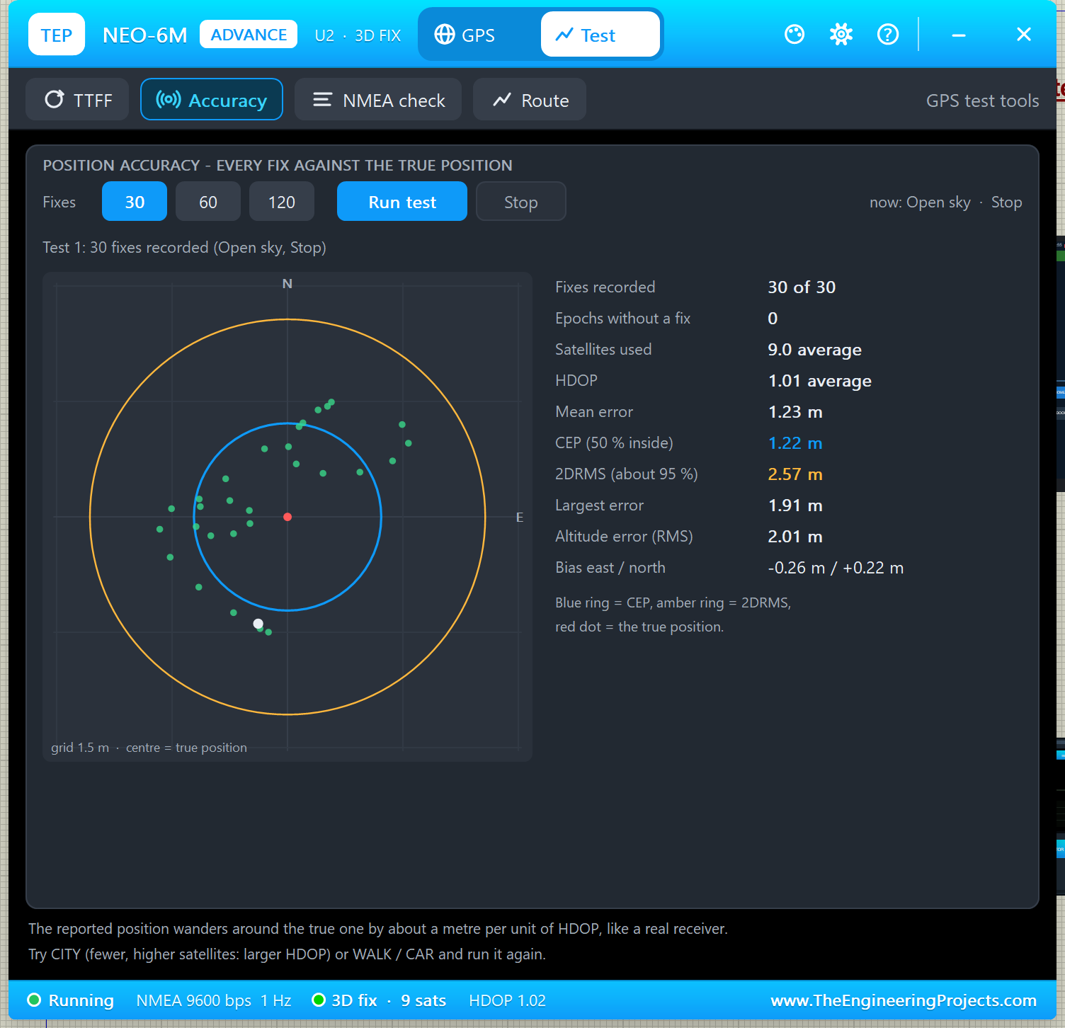
- CEP 1.22 m (blue ring): half of the fixes were within 1.22 m of the true position.
- 2DRMS 2.57 m (amber ring): about 95 % of the fixes were within 2.57 m.
- Mean error 1.23 m, largest error 1.91 m, altitude error 2.01 m, bias -0.26 m east / +0.22 m north.
- 30 of 30 fixes, 9 satellites and HDOP 1.01 on average.
The position wanders by about a metre per unit of HDOP, like a real receiver. Try it again with CITY on the GPS page: with fewer, higher satellites, the HDOP and the errors grow. In this PC render of the window, the city test gave HDOP 1.97 with 6 satellites, CEP 2.21 m and 2DRMS 4.78 m:
3. NMEA Check
The NMEA check reads the bytes that leave the TX pin again and checks every sentence:
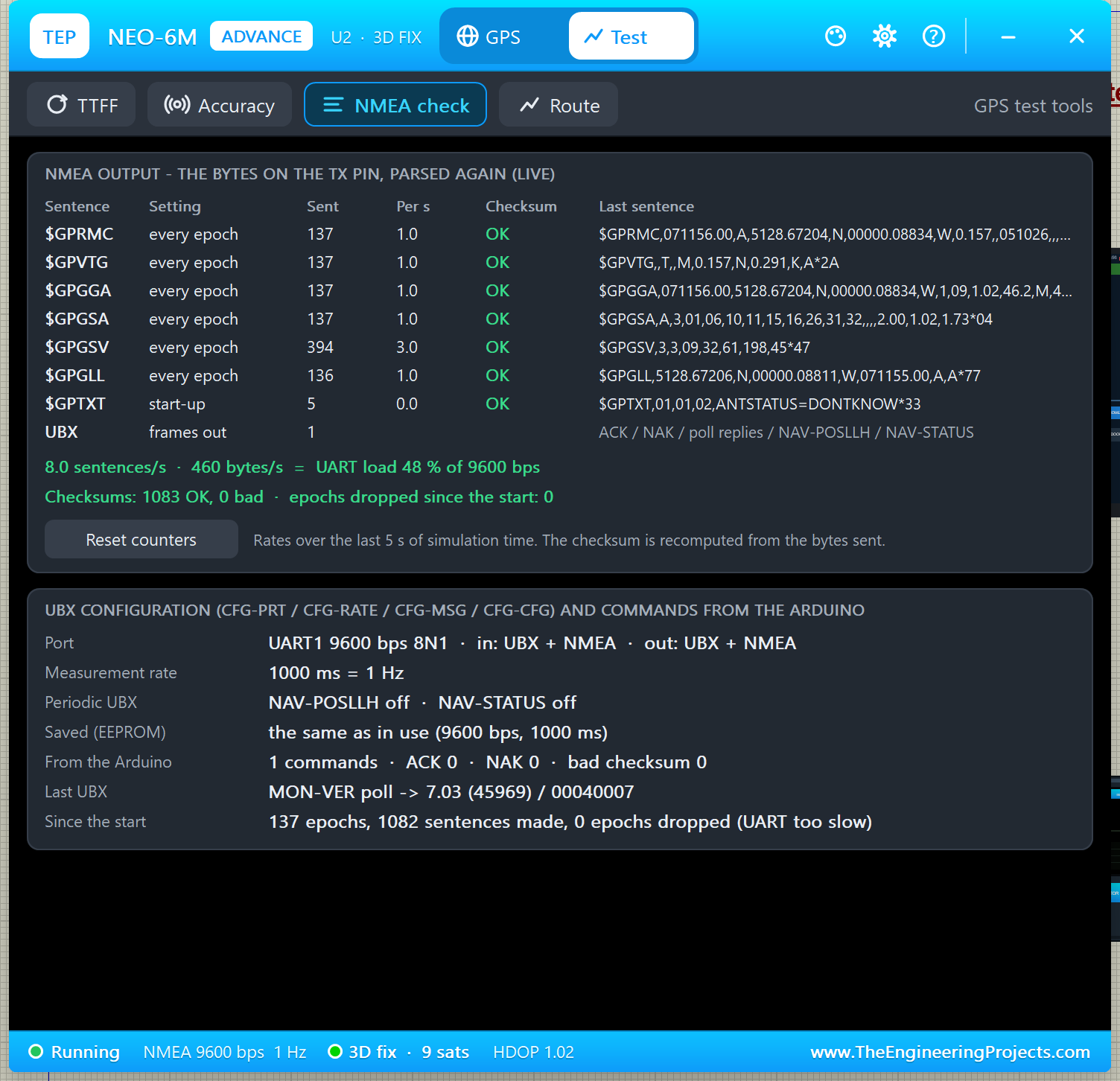
In my run: RMC, VTG, GGA, GSA and GLL once per second, GSV three times per second, five $GPTXT lines at start-up, 8.0 sentences/s and 460 bytes/s, which is a UART load of 48 % of 9600 bps. Checksums: 1083 OK, 0 bad, and no epoch dropped. The lower card shows the UBX configuration (UART1 9600 bps 8N1, measurement rate 1000 ms = 1 Hz, what is saved in the EEPROM) and the commands from the Arduino: the demo sketch's MON-VER poll was answered with "7.03 (45969) / 00040007".
Why does the UART load matter? If you raise the rate to 5 Hz with CFG-RATE and keep all six sentences at 9600 baud, the line is full. The real module then drops whole epochs, and so does our model:
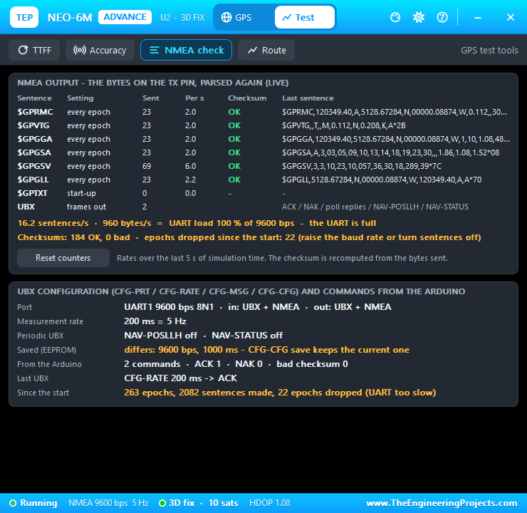
The fix is to raise the baud rate with CFG-PRT or turn sentences off with CFG-MSG. Good for: checking that your UBX set-up code really changed the module.
4. Route
The route test sets the motion to WALK (5 km/h) or DRIVE (50 km/h), records every fix for 30 s, 60 s or one lap, and compares the distance from the fixes with the true distance. I drove for 30 s:
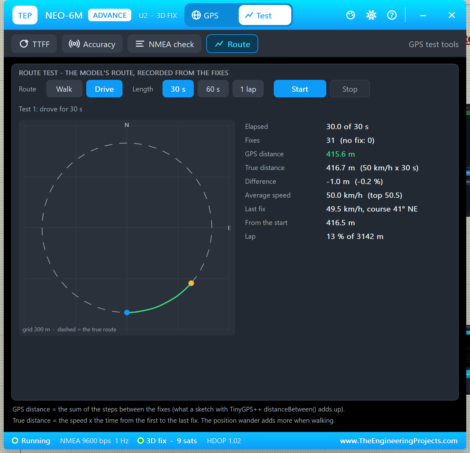
31 fixes, a GPS distance of 415.6 m against a true distance of 416.7 m (50 km/h x 30 s), a difference of only -0.2 %, an average speed of 50.0 km/h, and 13 % of the 3142 m lap. The GPS distance is the sum of the steps between the fixes, the same value a sketch gets by adding TinyGPS++ distanceBetween(). Choose 1 lap to drive the whole circle:
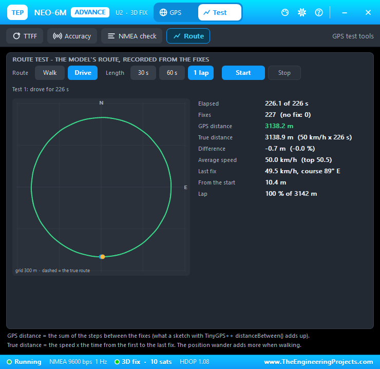
When walking, the GPS distance comes out a little longer than the true one, because the small position wander adds up when you move slowly. That is a real GPS effect too. After the test, the motion goes back to STOP.
Settings and Help
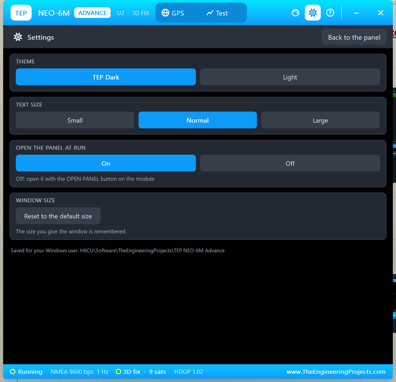
These pages work like in our HC-12 Library for Proteus and HC-05 Library for Proteus. The gear icon opens Settings: theme (TEP Dark or Light), text size, open the panel at Run (On / Off) and the window size, saved for your Windows user.
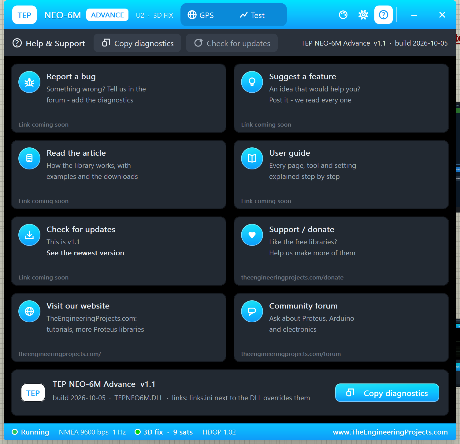
The ? icon opens Help & Support: eight cards (report a bug, suggest a feature, read the article, user guide, check for updates, support / donate, our website, community forum) and Copy diagnostics, which copies the state, position, configuration and test results for a bug report.
NEO-6M with Arduino in Proteus
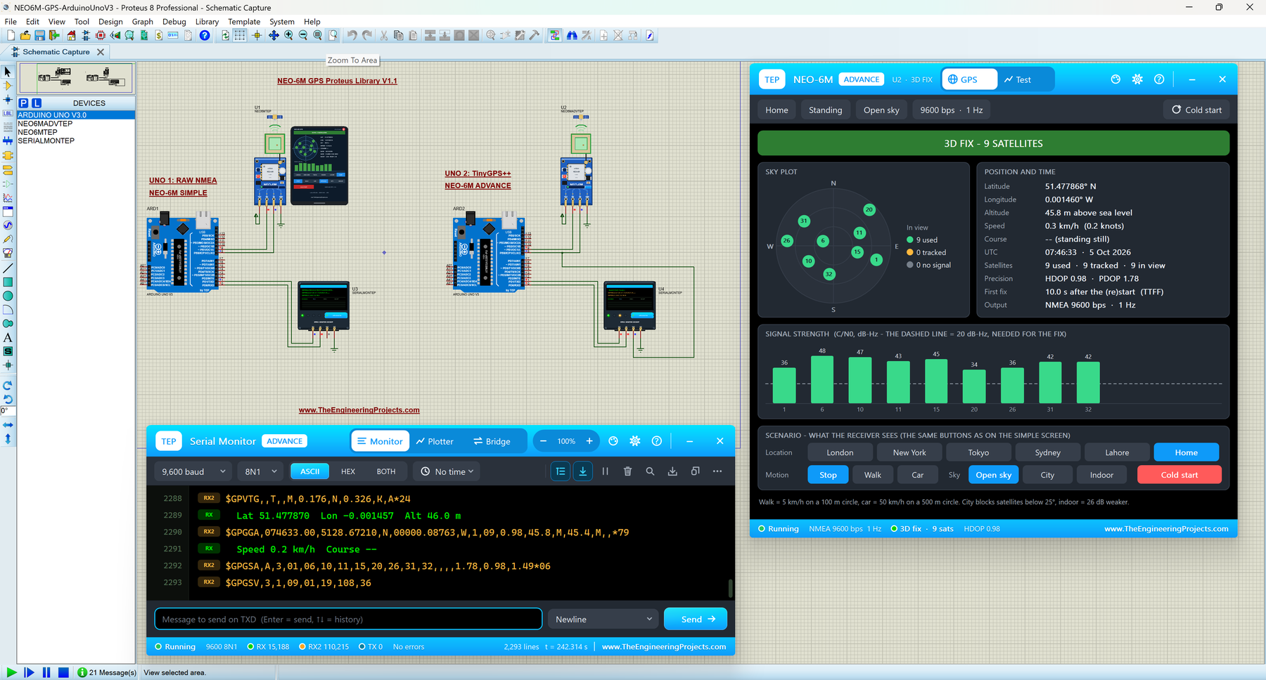
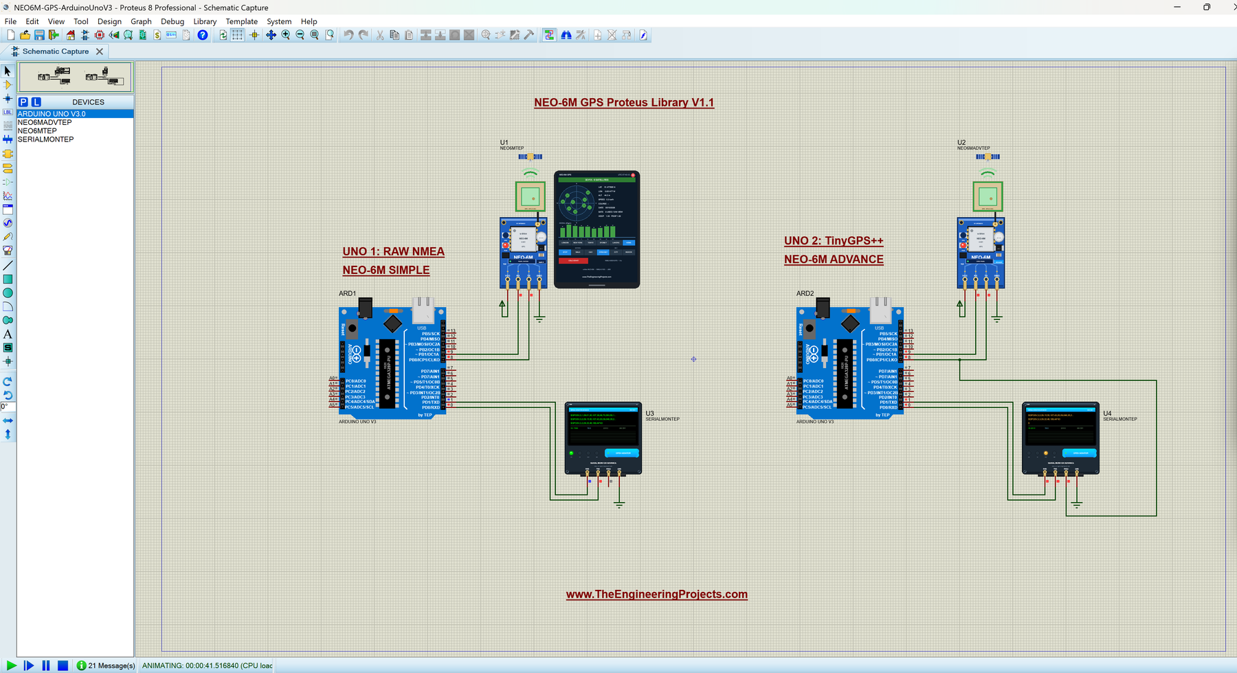
Now let's connect the GPS to an Arduino. Open NEO6M-GPS-ArduinoUnoV3.pdsprj from the Proteus Simulation folder. It has two Arduino UNOs from our Arduino Library for Proteus V3.0:
- UNO 1 (ARD1) runs
NEO6M_Raw_NMEAwith the NEO-6M Simple (U1) and Serial Monitor U3. - UNO 2 (ARD2) runs
NEO6M_TinyGPSwith the NEO-6M Advance (U2) and Serial Monitor U4.
Wiring
| From | To | Why |
|---|---|---|
| NEO-6M TX | Arduino D8 | AltSoftSerial RX: the NMEA sentences |
| NEO-6M RX | Arduino D9 | AltSoftSerial TX: the UBX commands |
| NEO-6M VCC / GND | +5 V / ground | Power |
| Serial Monitor RXD | Arduino D1 (TX) | Shows what the Arduino prints |
| Serial Monitor TXD | Arduino D0 (RX) | Sends what you type |
| U4 RXD2 | NEO-6M TX (the D8 net) | Watches the raw NMEA beside the TinyGPS++ output |
| Serial Monitor GND | Ground | Common ground |
Want to know more about these pins? Read our Introduction to Arduino UNO.
Why AltSoftSerial and Not SoftwareSerial?
Most NEO-6M examples use SoftwareSerial. In Proteus 8.5, it can send but cannot receive: it needs pin-change interrupts, which the Proteus 8.5 ATmega328P model never runs. Your GPS would work on its screen, but the Arduino would receive nothing. AltSoftSerial (Paul Stoffregen, MIT licence) uses Timer1 instead, works in Proteus and on real boards, and always uses D8 (RX) and D9 (TX) on the UNO. Don't use D10 while it runs. You can also use the hardware Serial port or an Arduino Mega (Serial1 to Serial3).
Sketch 1: Raw NMEA
The first sketch, NEO6M_Raw_NMEA.ino, simply copies every byte from the GPS to the Serial Monitor:
AltSoftSerial gpsSerial;               // RX = D8 (from GPS TX), TX = D9 (to GPS RX)

void setup() {
  Serial.begin(9600);
  gpsSerial.begin(9600);               // NEO-6M default: 9600 bps 8N1
  Serial.println(F("NEO-6M raw NMEA output (9600 baud):"));
}

void loop() {
  while (gpsSerial.available()) Serial.write(gpsSerial.read());
}
This is the best first test with any GPS module: if you see the sentences, the wiring and the baud rate are right.
Sketch 2: TinyGPS++
The second sketch, NEO6M_TinyGPS.ino, uses TinyGPS++ by Mikal Hart to decode the sentences:
AltSoftSerial gpsSerial;               // RX = D8 (from GPS TX), TX = D9 (to GPS RX)
TinyGPSPlus gps;
TinyGPSCustom satsInView(gps, "GPGSV", 3);   // field 3 of $GPGSV: satellites in view
At start-up, it asks the module for its firmware with the u-blox UBX command MON-VER. UBX is u-blox's binary protocol; its frames start with the bytes B5 62:
  const byte monVer[] = {0xB5, 0x62, 0x0A, 0x04, 0x00, 0x00, 0x0E, 0x34};
  gpsSerial.write(monVer, sizeof(monVer));
In loop(), every byte goes to TinyGPS++, and every 2 seconds the sketch prints a status block. When there is a valid, fresh location, it prints the fix:
  if (gps.location.isValid() && gps.location.age() < 3000) {
    Serial.print(F("  fix, "));
    Serial.print(gps.satellites.value());
    Serial.print(F(" satellites, HDOP "));
    Serial.println(gps.hdop.hdop());
    Serial.print(F("  Lat "));
    Serial.print(gps.location.lat(), 6);
    Serial.print(F("  Lon "));
    Serial.print(gps.location.lng(), 6);
Notice gps.location.age() < 3000: it treats a position older than 3 s as lost, so the sketch notices when the fix drops (try INDOOR or a TTFF test). If you change a sketch, compile it and load the new HEX file into the UNO; see How to get the HEX file from Arduino. New to Arduino? Start with our Arduino Tutorial for Beginners.
How to Run the Demo
- Open
Proteus Simulation\NEO6M-GPS-ArduinoUnoV3.pdsprj(keep the two .hex files and both DLLs beside it). - Press Run. Both Serial Monitors open at 9600 baud, and so does U2's pop-up.
- Wait for the fix (GPSTTFF = 10 s of simulation time; Proteus runs this design at about half real speed). Both GPS screens say 3D FIX, the PPS LEDs flash and the patches turn green.
- On U1's screen, click TOKYO and CAR, then INDOOR and OPEN SKY, and watch U3.
- In U2's pop-up, open the Test tab and try the four tools while you watch U4.
Simulation Results
Here is the demo after the fix, with the Advance GPS page on the left, U3 (UNO 1) at the top right and U4 (UNO 2) below it:
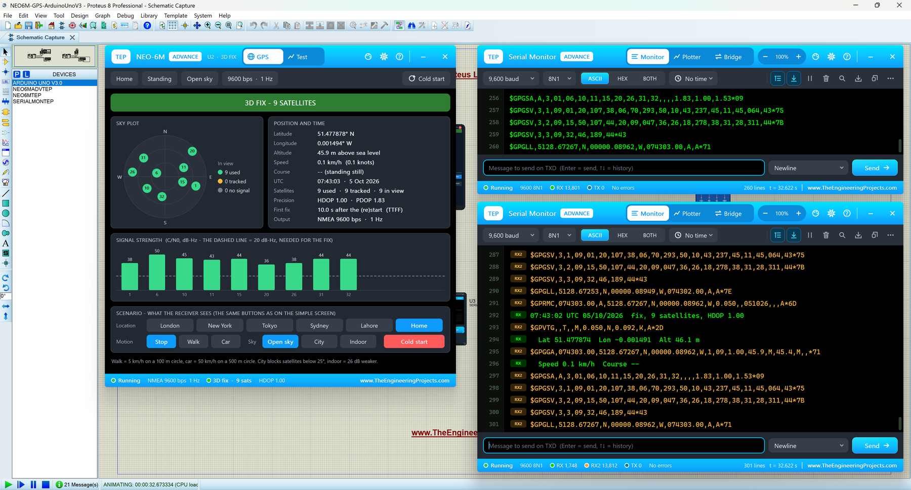
U3 starts with the u-blox start-up lines and the empty no-fix sentences, then fills in after the fix:
NEO-6M raw NMEA output (9600 baud):
$GPTXT,01,01,02,u-blox ag - www.u-blox.com*50
...
$GPRMC,,V,,,,,,,,,,N*53
...
$GPGSA,A,3,01,06,10,11,15,20,26,31,32,,,,1.83,1.00,1.53*09
$GPGSV,3,1,09,01,20,107,38,06,70,293,50,10,43,237,45,11,45,064,43*75
$GPGSV,3,2,09,15,50,107,44,20,09,047,36,26,18,278,38,31,28,311,44*7B
$GPGSV,3,3,09,32,46,189,44*43
$GPGLL,5128.67267,N,00000.08962,W,074303.00,A,A*71
U4 prints the firmware from MON-VER, then a status block every 2 s:
NEO-6M + TinyGPS++
u-blox firmware: 7.03 (45969), hardware: 00040007
--:--:-- UTC  no fix - 0 satellites in view
...
07:43:02 UTC 05/10/2026  fix, 9 satellites, HDOP 1.00
  Lat 51.477874  Lon -0.001491  Alt 46.1 m
  Speed 0.1 km/h  Course --
Between these lines, U4 shows the module's own sentences in amber with an RX2 tag, for example $GPGGA,074303.00,5128.67267,N,00000.08962,W,1,09,1.00,45.9,M,45.4,M,,*71. So you see what the GPS sends and what TinyGPS++ makes of it in one window. Read all about the monitor in TEP Serial Monitor Advance for Proteus.
Viewing the NMEA Data with TEP Serial Monitor Expert
Reading NMEA sentences by eye is hard. Our TEP Serial Monitor Expert for Proteus has an NMEA viewer that decodes them for you. To try it, install the Expert library, replace U3 or U4 with Serial Monitor Expert (device SERIALMONXTEP, the same four pins) and wire it the same way. For U4, set its BAUD2 to 9600, like the demo's monitor. At Run, click the panel button at the right of the Monitor toolbar and pick the NMEA page.
Here is U4 as a Serial Monitor Expert while U2 drives with CAR. The NMEA viewer reads the sentences on RX2, while the log shows the TinyGPS++ lines (RX, green) between them:
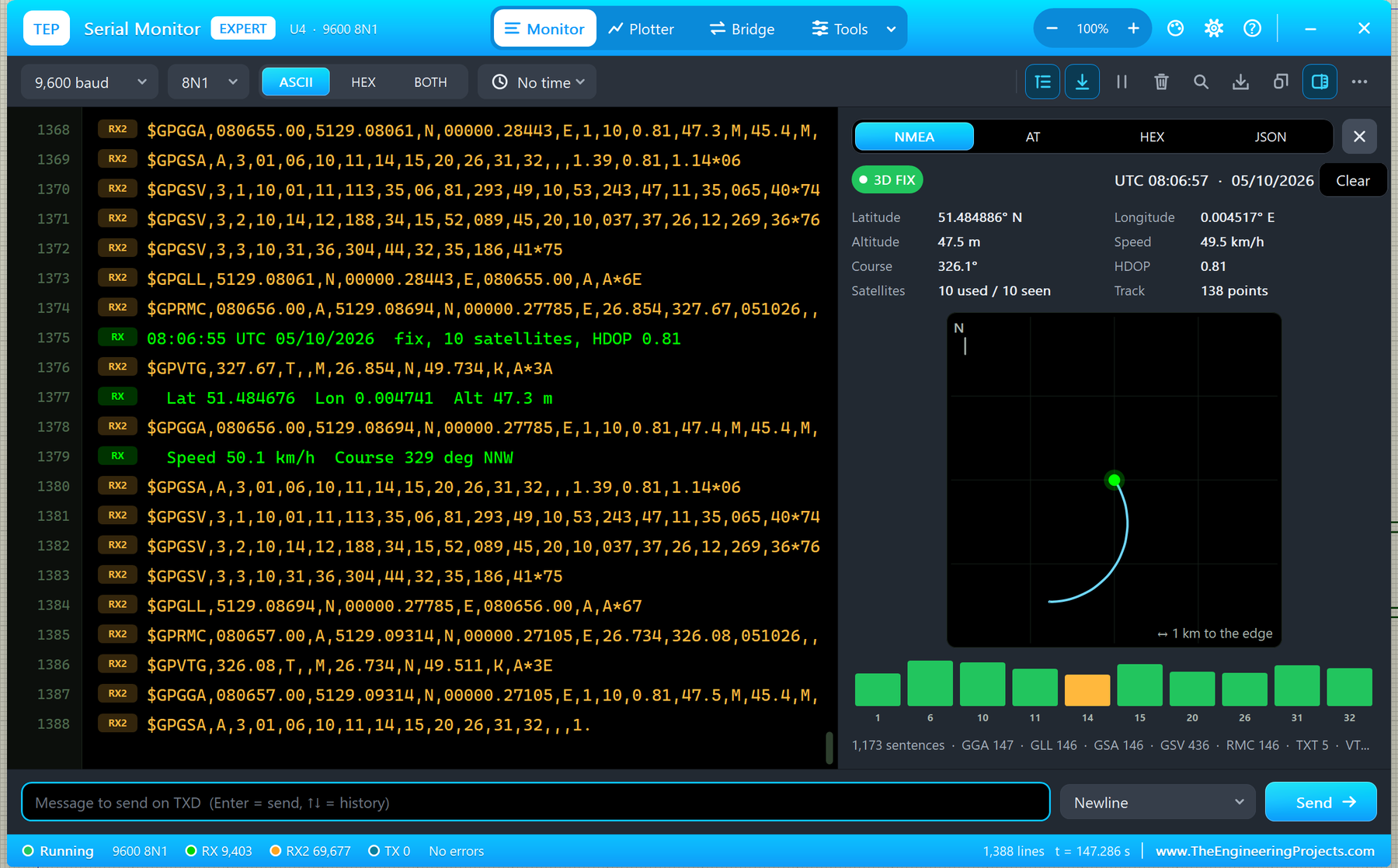
- Fix and time: a 3D FIX chip and UTC 08:06:57 · 05/10/2026.
- Values: 51.484886° N, 0.004517° E, 47.5 m, 49.5 km/h, course 326.1°, HDOP 0.81, 10 used / 10 seen.
- Track map: 138 points of the car's circle; the scale grows by itself ("1 km to the edge").
- Satellite bars: green from 35 dB-Hz, amber from 25, red below that.
- Counters: 1,173 sentences · GGA 147 · GLL 146 · GSA 146 · GSV 436 · RMC 146 · TXT 5, and any bad checksum.
And here is U3 as a Serial Monitor Expert, with the raw NMEA of UNO 1 standing at HOME. The track map zooms in to "20 m to the edge", so you can see how the position wanders around the true point:
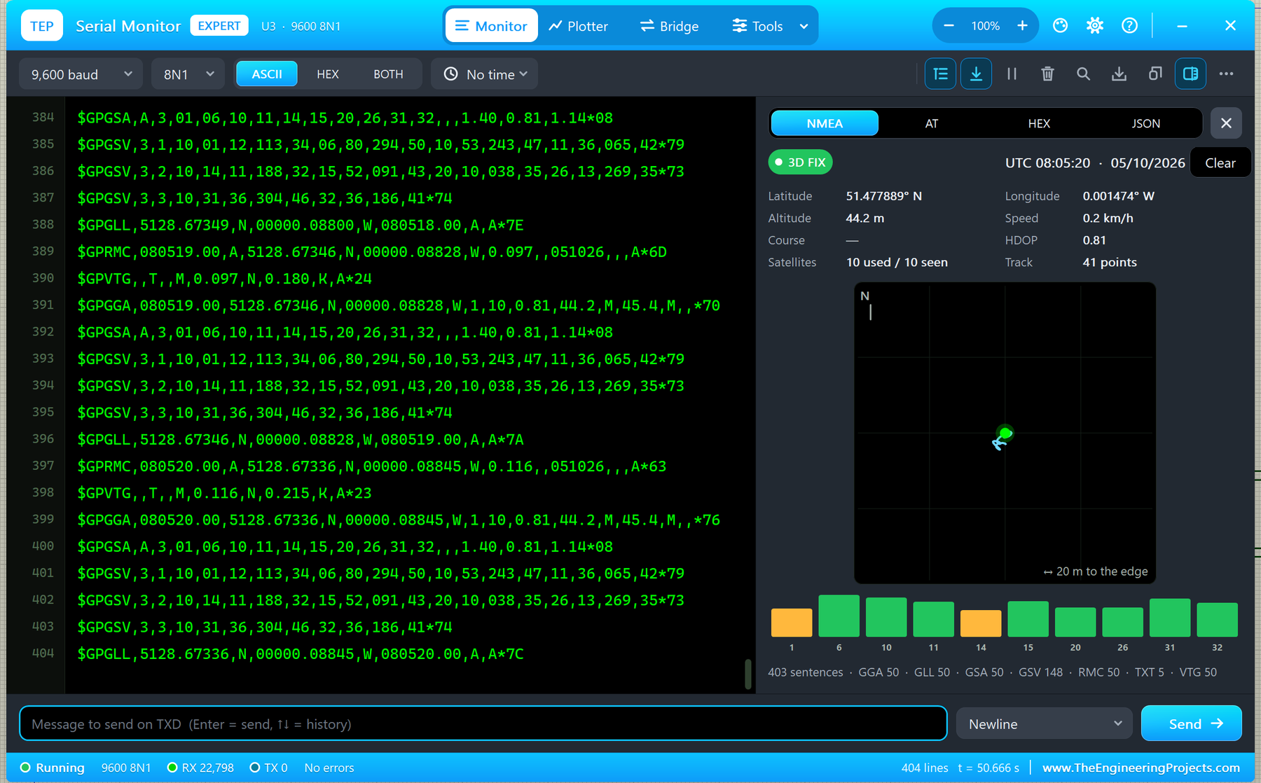
This makes a great pair: the GPS screen shows what the module thinks, and the NMEA viewer shows what your Arduino actually receives. If they disagree, look at your wiring or your sketch.
UBX Commands Supported by the NEO-6M Model
Besides NMEA, the module answers these u-blox UBX commands on its RX pin (frames start with B5 62, and the checksum is checked):
| Command | What it does |
|---|---|
| CFG-PRT (06 00) | Poll, or set the UART baud rate (4800 - 230400, 8N1) and the protocols; the ACK comes at the old speed, then the module switches |
| CFG-RATE (06 08) | Poll, or set the measurement rate: 200 ms (5 Hz) and slower; faster gives a NAK |
| CFG-MSG (06 01) | Poll, or set the rate of GGA, GLL, GSA, GSV, RMC, VTG, NAV-POSLLH and NAV-STATUS |
| CFG-RST (06 04) | Hot, warm or cold start, or a restart; no acknowledge, like the real one |
| CFG-CFG (06 09) | Clear, save or load the configuration (EEPROM) |
| MON-VER (0A 04) | Poll: "7.03 (45969)", "00040007" |
| NAV-POSLLH (01 02), NAV-STATUS (01 03) | Poll or periodic |
| Other CFG commands | NAK |
Changed the baud rate? After the ACK, your sketch must switch gpsSerial to the new speed, or it reads garbage.
Troubleshooting
No Fix
Wait GPSTTFF seconds of simulation time, and check that SKY is not INDOOR.
The Monitor Shows Nothing from the GPS
The GPS TX must go to D8 (not D0), and the sketch must use AltSoftSerial, the hardware Serial port or a Mega, not SoftwareSerial.
"No reply to MON-VER"
The Arduino's D9 must go to the module's RX pin.
No GPS Screen, No Pop-Up or No Monitor
TEPNEO6M.DLL or TEPSERIALMON.DLL is missing from MODELS and the project folder. For the Advance, click OPEN PANEL or turn "Open the panel at Run" back on in Settings.
The Red X Does Not Close the Screen
Your design still holds the v1.0 symbol. Replace TEPNEO6M.LIB, delete TEPNEO6M.IDX and pick the part again.
Things to Know Before Using a Real NEO-6M
- Power: GY-NEO6MV2 boards take 3.3 - 5 V on VCC (there is a regulator on the board).
- 3.3 V logic on RX: the module's RX is a 3.3 V input. Use a 1 k / 2 k divider from the Arduino's 5 V D9: 1 k from D9 to RX, and 2 k from RX to GND.
- Sky view: put the patch antenna under the open sky, facing up. Indoors, a real NEO-6M usually gets no fix.
- First fix: the data sheet gives 27 s for a cold start; our model uses 10 s (GPSTTFF) to keep demos short.
- Backup cell: on the real board, the ML1220 keeps data for faster restarts. Our model does not simulate it, so every power-up is a cold start.
Limitations of the Simulation
- The satellites are a simplified GPS constellation (30 satellites in 6 planes), not the real sky of that day; the satellites and DOP values are realistic in kind.
- Warm and cold start take the same time, as in the NEO-6 data sheet.
- Not modelled: SBAS / DGPS, power save modes, the antenna supervisor, the other ports (USB, SPI, I2C), other UBX messages, $PUBX commands and the supply current.
- Tested in Proteus 8.5 (the demo and every Proteus screenshot in this article) and with 672 automatic checks on the PC; Proteus 7 is not supported.
Want to send your GPS position over the air? Try our HC-12 Library for Proteus or our HC-05 Library for Proteus.
So, that was all about the NEO-6M GPS Library for Proteus V1.1. I hope the GPS screen, the test tools and the NMEA viewer make GPS projects much easier to understand. Please share your feedback in the comments or in our forum, and if you have any questions, ask in the comments and I will help you out. Till the next tutorial, take care and have fun!
Comments
0