


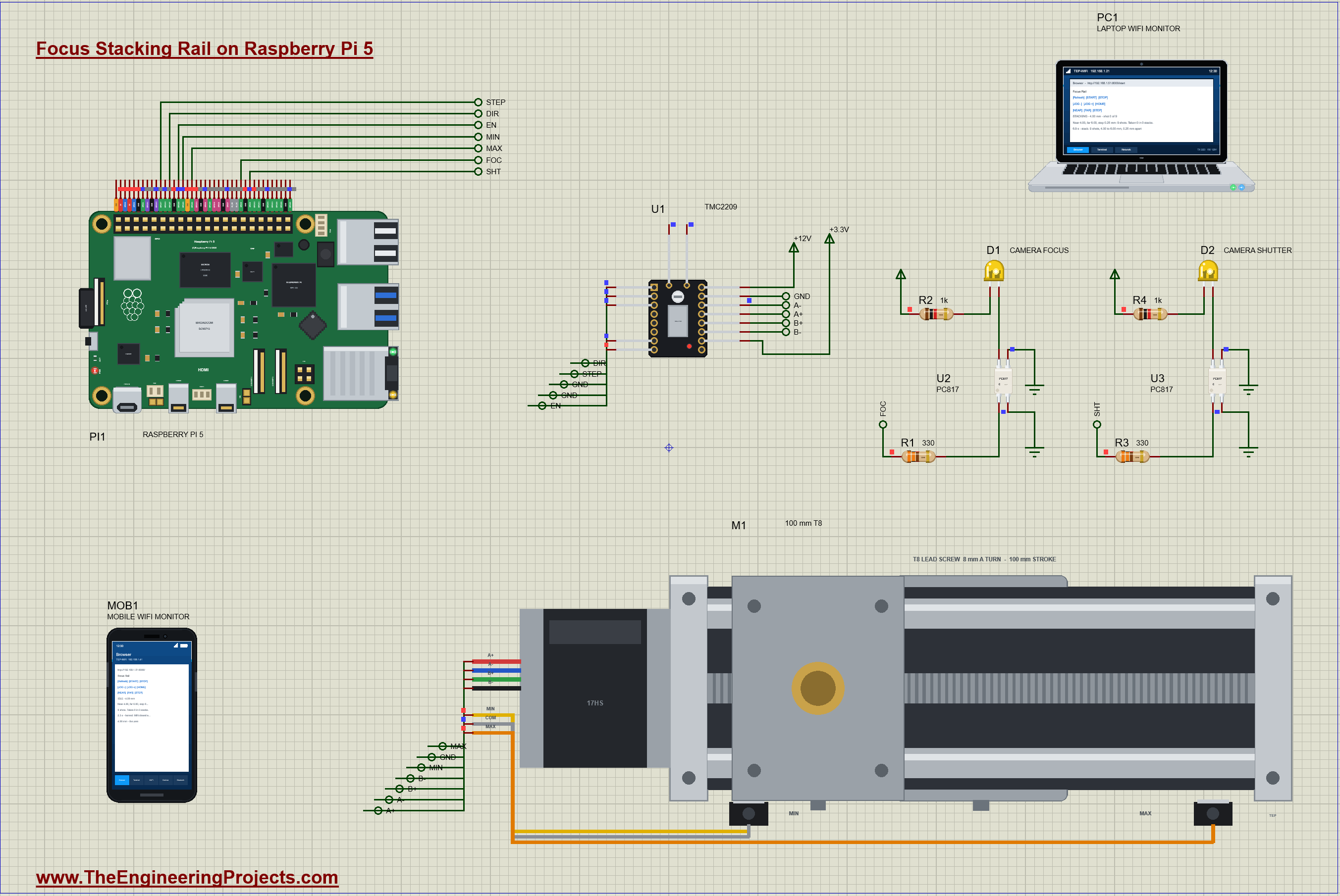
Focus Stacking Rail on Raspberry Pi 5: Proteus Simulation Project


Hello friends, I hope you all are doing great. Today, I am going to share the Focus Stacking Rail on Raspberry Pi 5: Proteus Simulation Project, the thirty-eighth project of our IoT Projects series. If you have searched for a Proteus simulation of a Raspberry Pi stepper motor project for macro photography, here is a complete one. A Raspberry Pi 5 drives a TMC2209 stepper driver and a NEMA 17 linear stage that carries a camera in steps of a few microns, finds its zero on an end switch, and takes a photo at every step through two PC817 optocouplers wired like a camera's remote cable. A live web dashboard, on a laptop or a phone, sets the near and far ends and the step, and starts or stops the stack.
Anyone who has photographed a fly's eye or the pins of a chip knows the problem: up close, only a sliver of the subject is sharp, often less than half a millimetre. Focus stacking solves it by taking many photos, each focused a little deeper, and merging the sharp parts in software. Doing that by hand is slow and shaky, so macro photographers use a motorized focus rail. In this tutorial, we will go through the circuit, work out how many shots a subject needs from the depth of field, learn how a lead screw and microstepping give 5 micron steps, home the rail on its end switch, trigger a camera safely through optocouplers, walk through the Python program, and then run the simulation: homing, a 9-shot stack with the camera's LEDs caught mid-shot, new settings from the phone, and a stack stopped halfway. At the end, you can download the project with the program, every library file and the Python runtime the Pi needs.
NOTICE: Our team has put a lot of effort into this project: the circuit, the code and every part in the simulation are our own work, and you get them all free. Your feedback is the fuel that keeps us going, so please tell us what you think in the comments below. And if our free projects help you, you can buy us a coffee. So, let's get started with the Focus Stacking Rail on Raspberry Pi 5: Proteus Simulation Project:
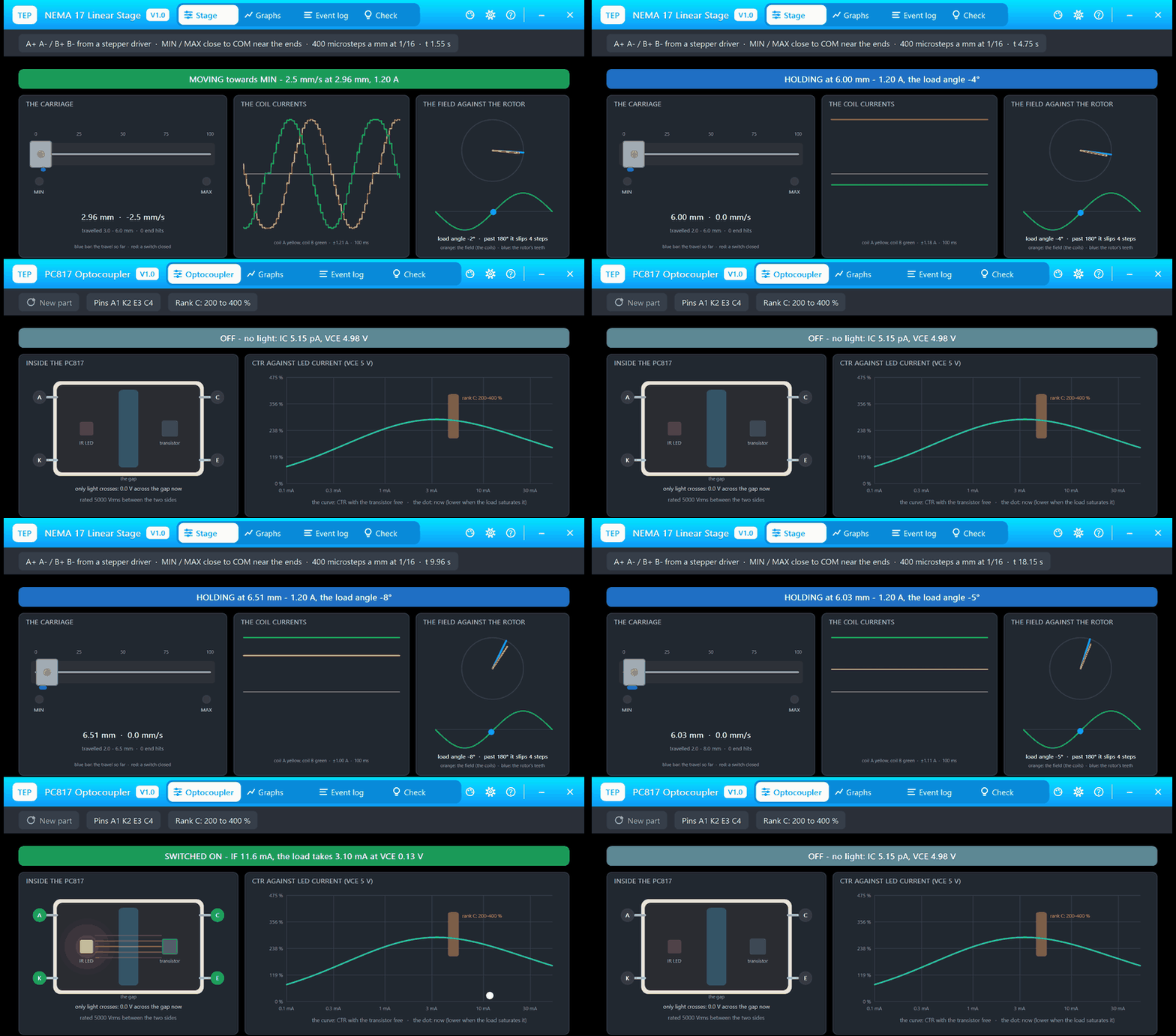
What Does This Focus Stacking Rail Do?
- Moves a camera in tiny steps: 5 microns a pulse along a 100 mm stage, from 0.05 to 0.5 mm a shot.
- Finds its own zero: at power-up the rail homes on its MIN switch, fast first and then slowly for a repeatable zero.
- Takes the photos: at each step it waits for the rail to settle, half-presses FOCUS, presses SHUTTER and waits for the exposure.
- Keeps the camera isolated: two PC817 optocouplers press the camera's buttons; the Pi and the camera share no wire.
- Holds still: the TMC2209 stays on between shots, so the motor's holding torque keeps the camera exactly in place.
- A dashboard: START, STOP, JOG, HOME, set NEAR and FAR from the position, choose the STEP, from a laptop or a phone.
It is a great project for learning how stepper motors and lead screws make precise motion, how a driver turns STEP pulses into microsteps, how to home a machine on a switch, and how to switch another device safely through an optocoupler. In the simulation, the stage's pop-up shows the carriage moving on its track, the TMC2209's pop-up shows the coil currents, and the camera's focus and shutter inputs are two yellow LEDs.
Components Used in the Proteus Simulation
All the parts come from our Proteus libraries, each with its own tutorial. The project zip at the end includes every LIB and DLL file.
| Part | Proteus device | Library post | Connection |
|---|---|---|---|
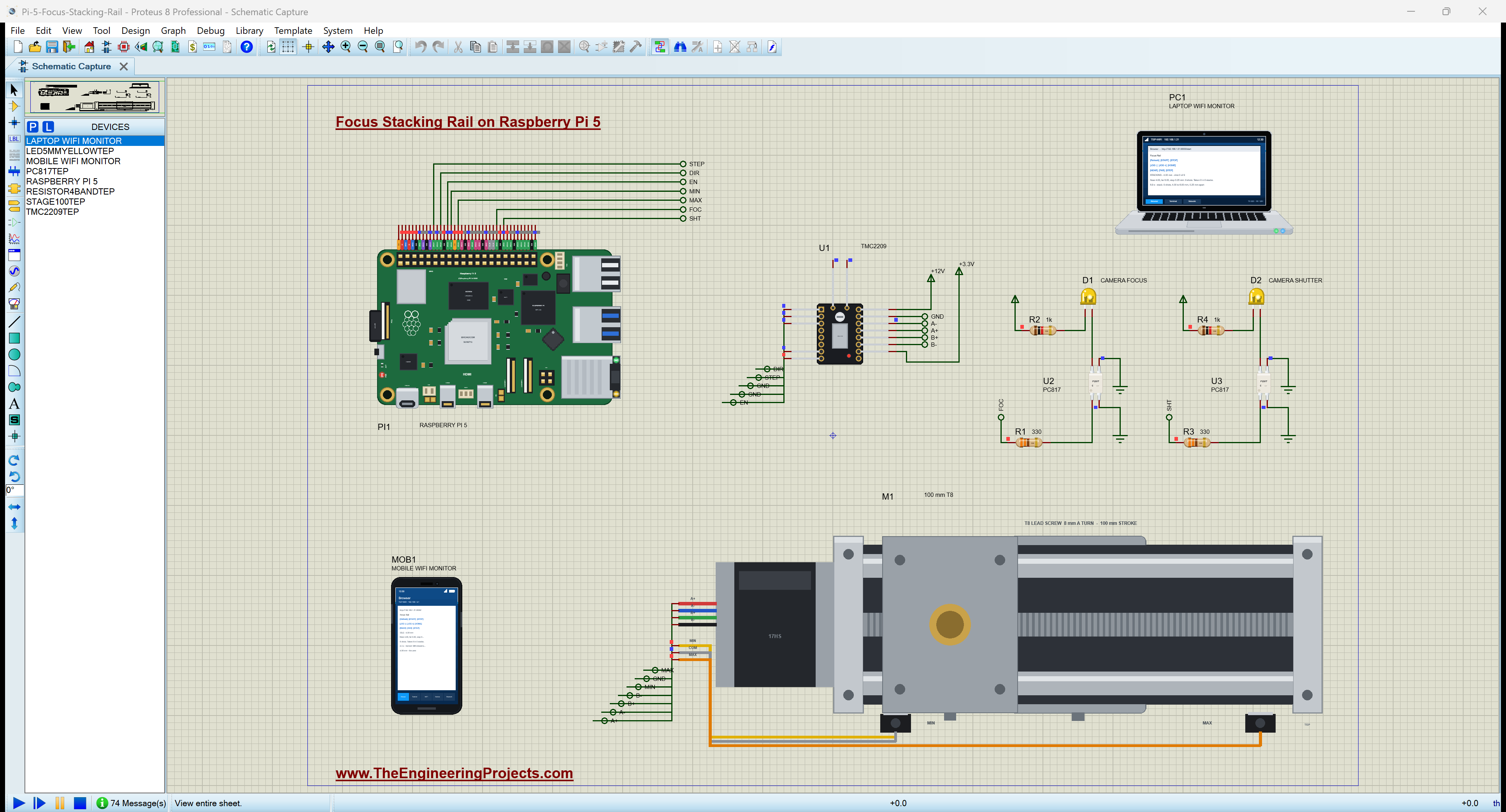
| Raspberry Pi 5 | RASPBERRY PI 5 | Raspberry Pi 5 Library for Proteus | PI1, Ethernet 192.168.1.51 |
| TMC2209 stepper driver | TMC2209TEP | TMC2209 Stepper Driver Library for Proteus | U1, STEP GPIO17, DIR GPIO27, EN GPIO22 |
| NEMA 17 linear stage, 100 mm | STAGE100TEP | NEMA 17 Linear Stage Library for Proteus | M1, MIN GPIO23, MAX GPIO24 |
| PC817 optocoupler x 2 | PC817TEP | PC817 Optocoupler Library for Proteus | U2 FOCUS GPIO5, U3 SHUTTER GPIO6 |
| Yellow LEDs x 2 | LED5MMYELLOWTEP | 5mm LED Library | D1 / D2, the camera's inputs |
| Resistors 330 and 1k | RESISTOR4BANDTEP | Resistor Library | R1 - R4 |
| Laptop WiFi Monitor | LAPTOP WIFI MONITOR | Laptop WiFi Monitor | PC1 |
| Mobile WiFi Monitor | MOBILE WIFI MONITOR | Mobile WiFi Monitor | MOB1 |
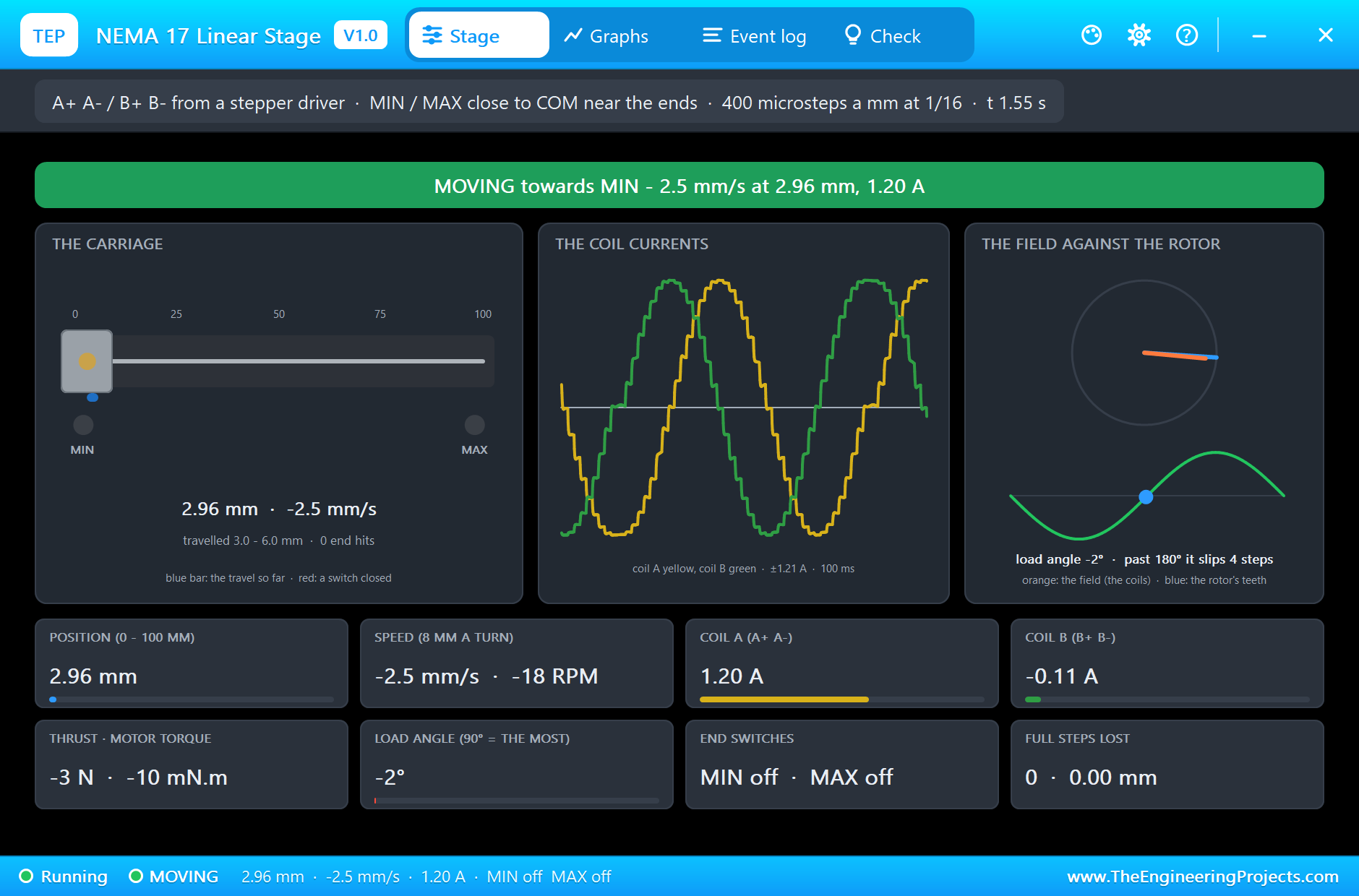
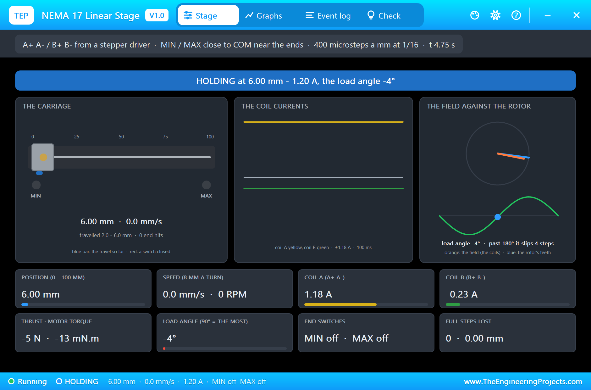
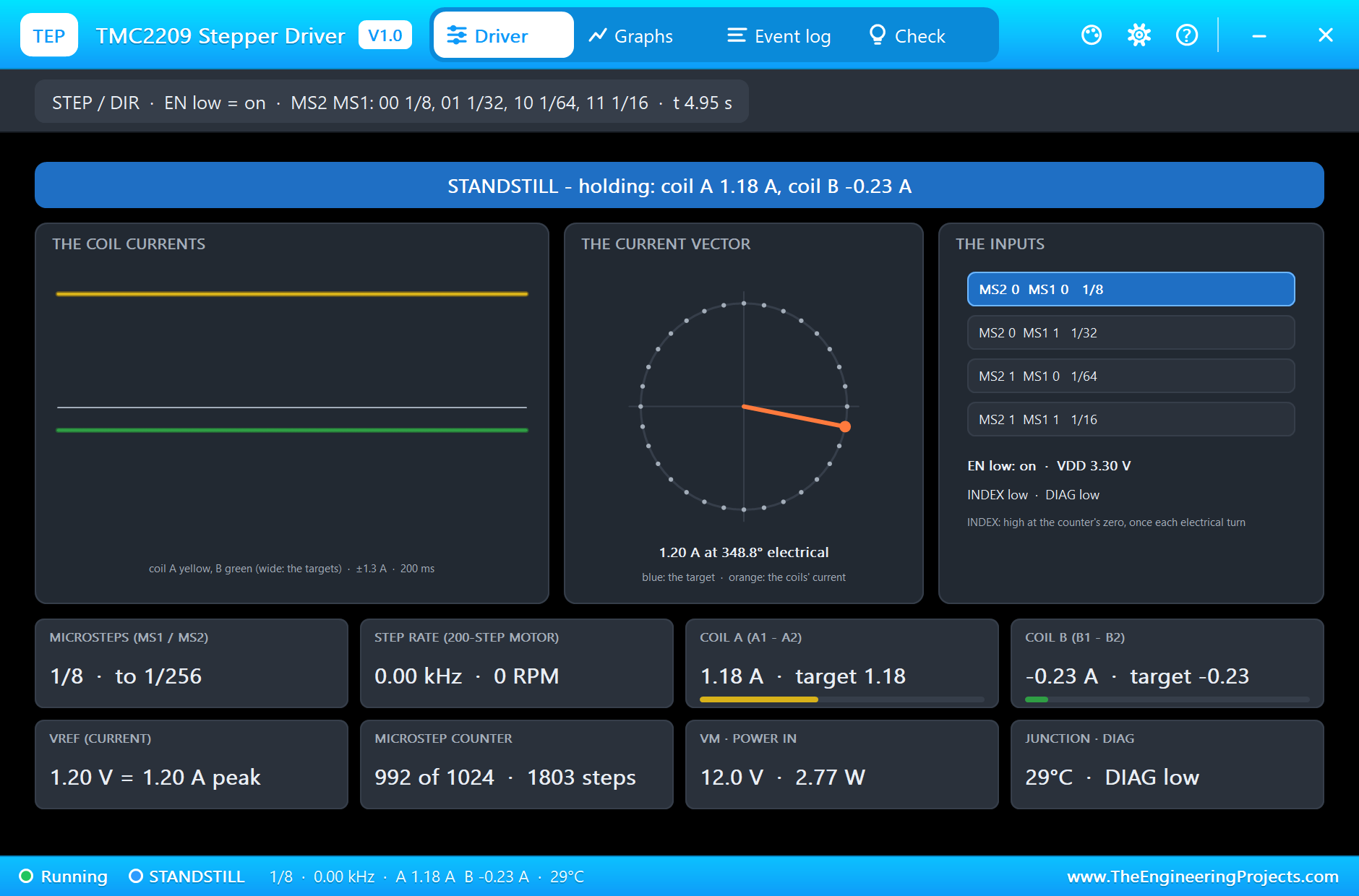
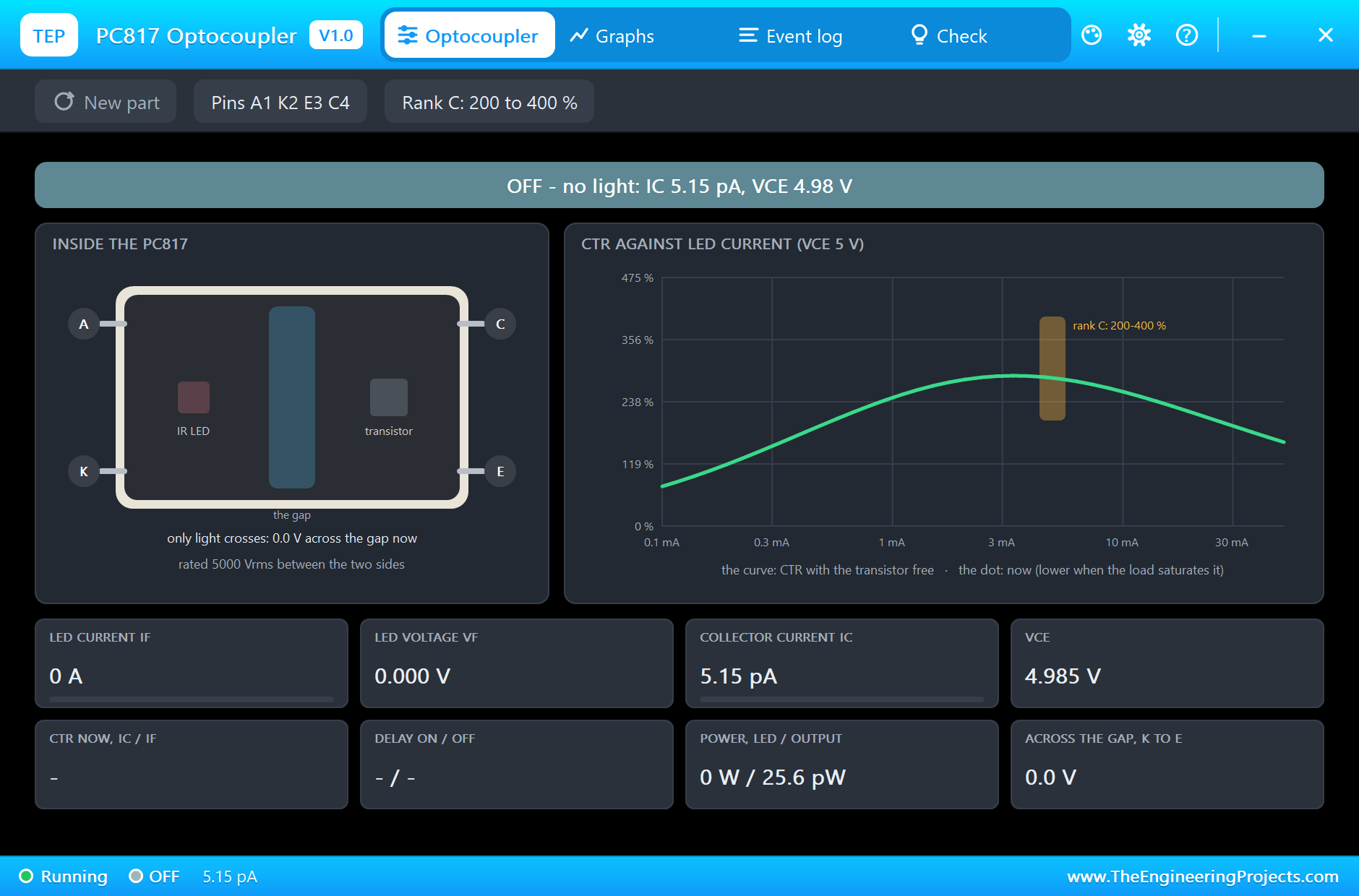
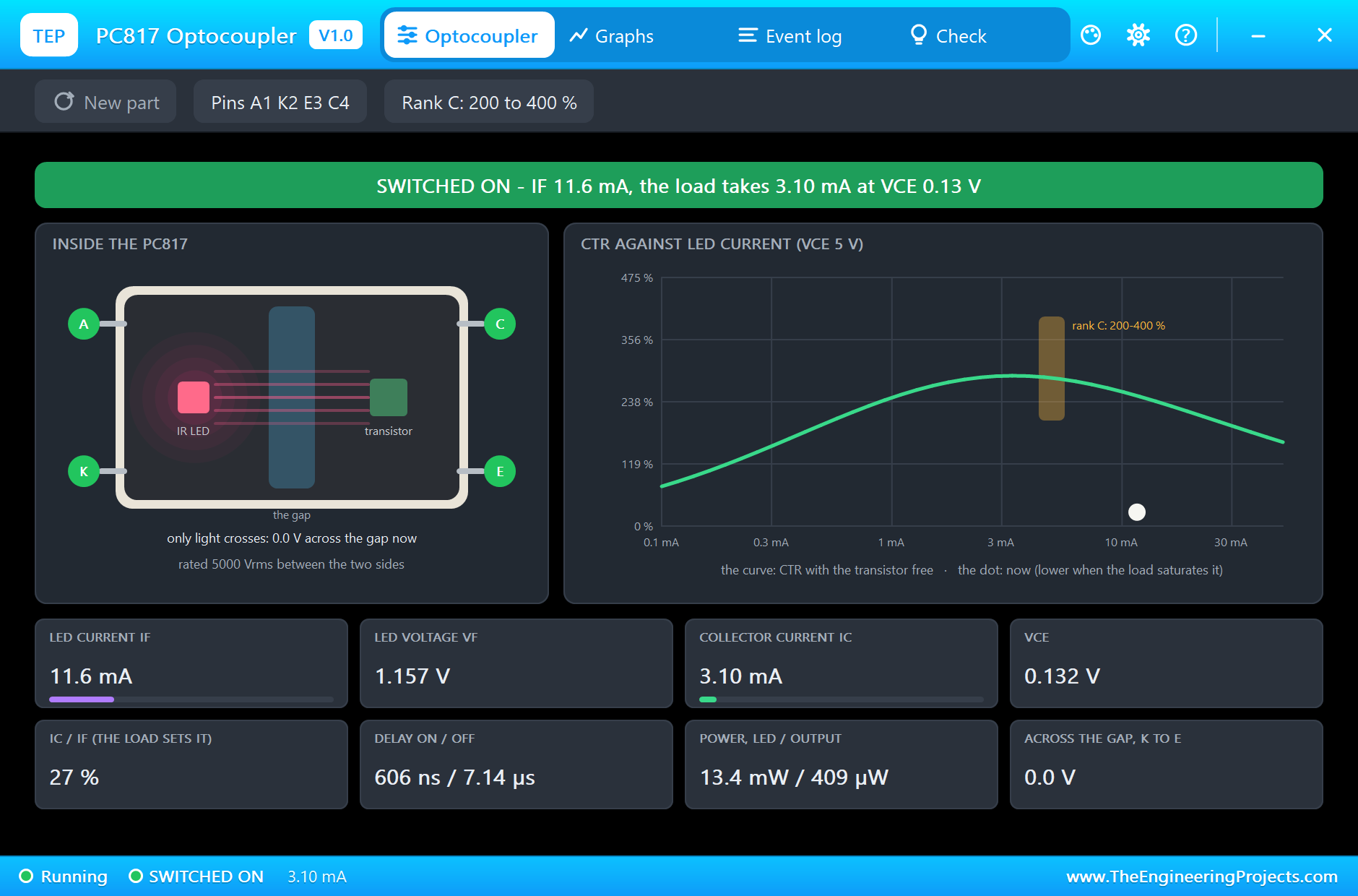
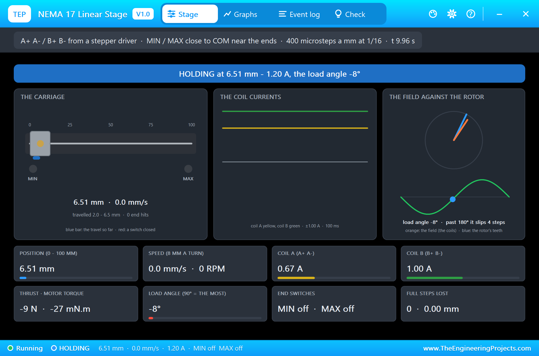
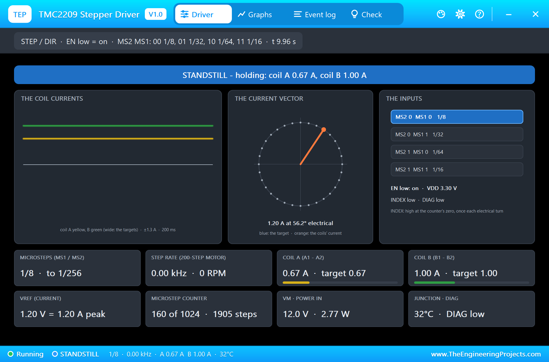
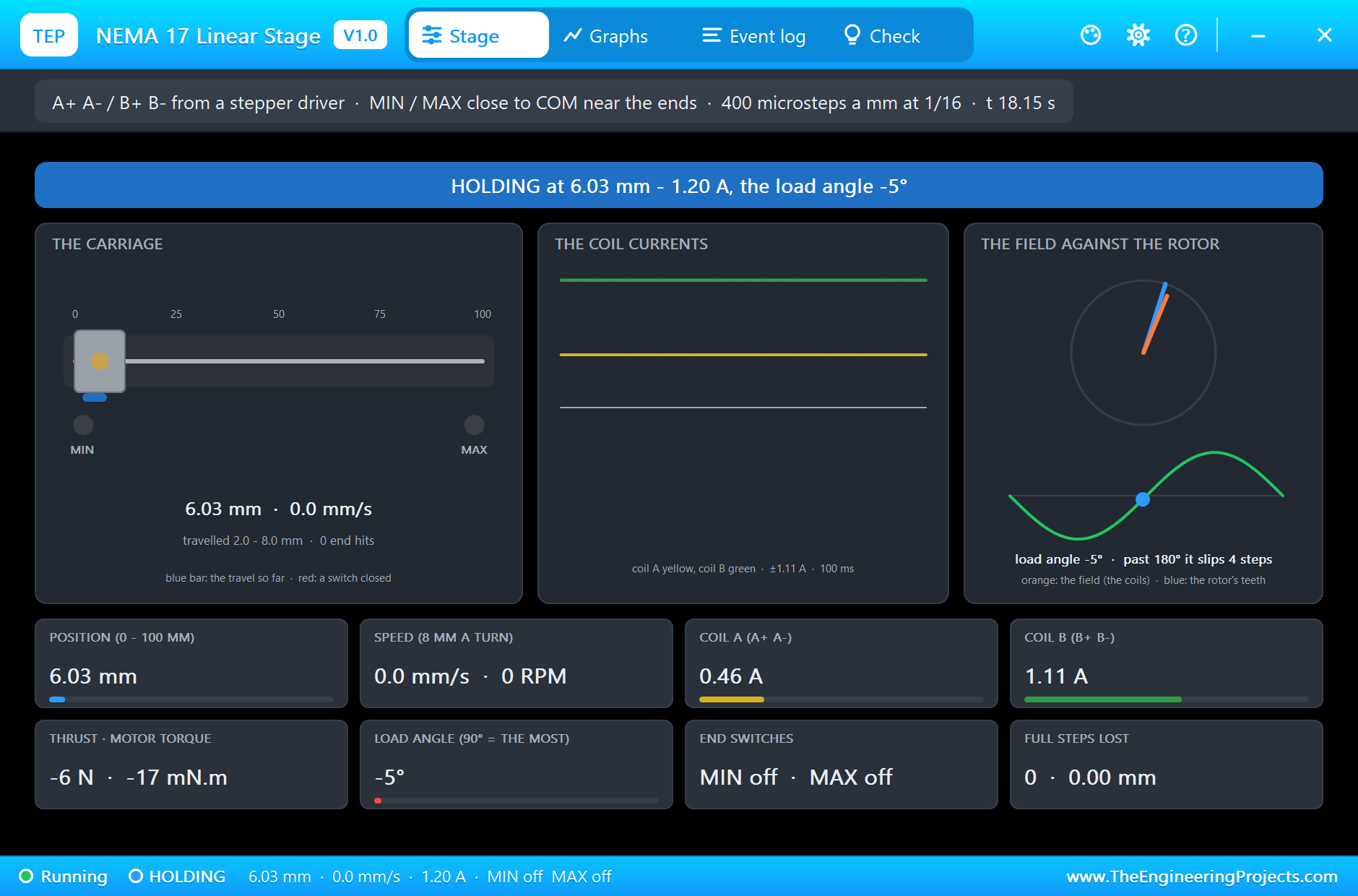
The TMC2209, the stage and the PC817s are models with pop-ups. The stage's pop-up draws the carriage on its 100 mm track with the switches, the two coil currents, the field against the rotor and the steps lost. The TMC2209's pop-up shows the coil currents against their targets, the current vector on its microstep circle and the MS1 / MS2 table. The PC817's pop-up shows the LED, the phototransistor and the current transfer ratio.
Proteus Simulation of the Focus Rail: the Circuit
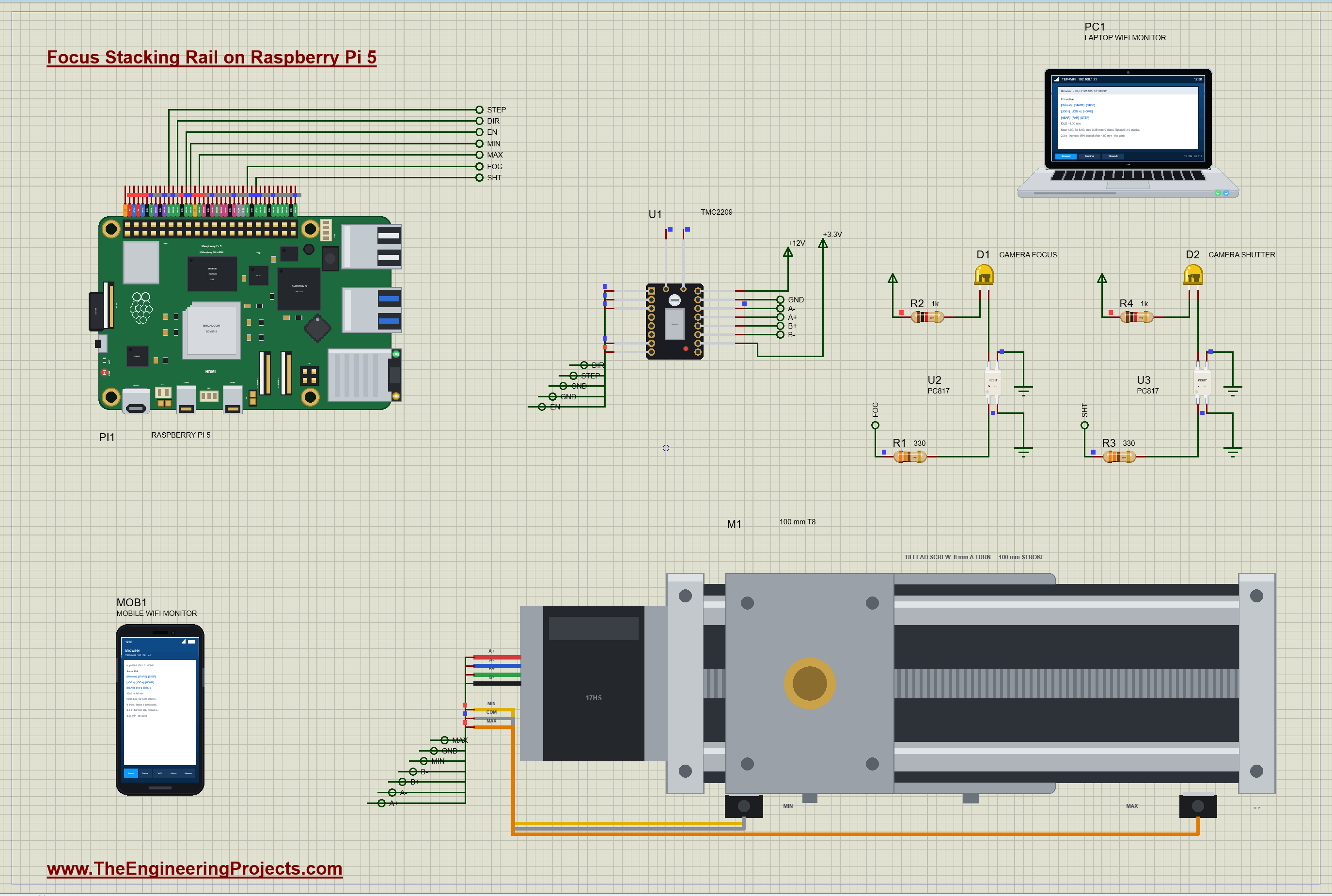
| Part | Pins | Raspberry Pi 5 header / other |
|---|---|---|
| U1 TMC2209 | STEP / DIR / EN | GPIO17 (pin 11) / GPIO27 (pin 13) / GPIO22 (pin 15) |
| U1 TMC2209 | MS1, MS2 / VM / VDD | GND (1/8 microsteps) / +12 V / +3.3 V |
| U1 to M1 | A1 A2 B1 B2 | the stage's A+ A- B+ B- |
| M1 stage | MIN / MAX / COM | GPIO23 (pin 16) / GPIO24 (pin 18), the Pi's pull-ups / GND |
| U2 / U3 PC817 | A / K | GPIO5 (pin 29) / GPIO6 (pin 31) through 330 ohm / GND |
| U2 / U3 PC817 | C / E | the camera's input (a yellow LED from 5 V through 1 kohm) / GND |
The stage is drawn at its true size, so it takes the whole bottom of the sheet: the NEMA 17 motor on the left, the two plates, the guide rods, the T8 lead screw and the carriage with its brass nut, the MIN and MAX switches below. The camera would sit on the carriage. Each PC817's transistor stands where a real remote cable's switch would be, between the camera's focus or shutter line and its ground.
How the Focus Stacking Rail Works
How Many Shots? The Depth of Field
In macro photography the depth of field is roughly 2 x N x c x (m + 1) / m squared, where N is the aperture, c the circle of confusion (about 0.03 mm on a full-frame sensor) and m the magnification. Worked example: at 2 times life size and f/8, it is 2 x 8 x 0.03 x 3 / 4 = 0.36 mm. A rail step of 0.25 mm keeps about a third of each slice overlapping the next, so the stacking software has sharp detail to join. A subject 2 mm deep, an insect's head, then needs 2 / 0.25 + 1 = 9 shots: exactly the stack this rail is set to at power-up, from 4.00 to 6.00 mm.
From Pulses to Microns: the Lead Screw and the TMC2209
The stage's motor is a 1.8 degree NEMA 17: 200 full steps a turn. The TMC2209 divides each step into microsteps by its MS1 and MS2 pins; both tied to ground give 1/8, so one turn takes 1600 STEP pulses. The T8 lead screw moves the carriage 8 mm a turn, so one millimetre is 200 pulses and one pulse is 5 microns. Worked example: the move from one shot to the next at 0.25 mm is 50 pulses; at 1000 pulses a second, 5 mm/s or 37.5 turns a minute, it takes 50 ms. The driver's VREF of 1.2 V sets 1.2 A peak in the coils, 70 % of the motor's 1.7 A rating, enough to push a 0.8 kg camera smoothly and cool enough to stay on all the time.
Homing on the MIN Switch
A stepper motor only counts steps; it has no idea where it is when the power comes on. So the rail homes: it moves back towards MIN in 0.2 mm bites at 3 mm/s, checking the switch after each bite. When MIN closes it backs off 0.5 mm and comes back in 10 micron bites at 0.5 mm/s, and the moment the switch closes again is the zero. The slow second approach makes the zero repeatable to a few microns, because the switch always closes at the same slow speed. In the simulation the stage starts with the carriage at 6 mm, and MIN closes 2 mm from the end of the track, so the program reports 4.00 mm of travel to the zero.
Triggering the Camera through Optocouplers
A camera's wired remote has three contacts: ground, focus and shutter. Shorting focus to ground is a half-press of the button, which wakes the camera and focuses; shorting shutter too is a full press. Inside the camera those lines are pulled up to a few volts, and the remote only needs to sink a fraction of a milliampere. A PC817 does exactly that, with light: the Pi lights its infrared LED with (3.3 - 1.2) / 330 = 6.4 mA, and its phototransistor, which can pass at least half of that at the PC817's lowest current transfer ratio, shorts the camera's line. The camera and the Pi stay electrically separate, so a fault in one cannot reach the other. In the simulation each camera input is a yellow LED from 5 V through 1 kohm, 2.8 mA when the optocoupler conducts.
The Python Code Explained
The whole program is included in the download. It uses lgpio for the GPIO pins and its tx_pulse function for the STEP pulses, a worker thread with a queue so the motor gets one job at a time, and the standard library's http.server for the dashboard. At the top are the scale and the speeds:
PER_MM = 200                                          # pulses a millimetre: 200 steps x 8 microsteps / 8 mm lead
MOVE_HZ, HOME_HZ, CREEP_HZ = 1000, 600, 100           # pulses a second: 5 mm/s moves, 3 mm/s homing, 0.5 mm/s for the last approach
The end switches use the Pi's own pull-up resistors, so a closed switch reads 0:
lgpio.gpio_claim_input(chip, MIN_SW, lgpio.SET_PULL_UP)The Pulses
lgpio's tx_pulse sends a train of n pulses timed by the Pi itself, far steadier than toggling the pin from Python; the program waits until the train is out:
lgpio.tx_pulse(chip, STEP, half, half, 0, n) lgpio.gpio_write(chip, DIR, 1 if n > 0 else 0)Homing
    while lgpio.gpio_read(chip, MIN_SW) == 1 and travel < 110 * PER_MM:
        drive(-40, HOME_HZ); travel += 40
drive(100, HOME_HZ) # off the switch: 0.5 mmThe Stack
n = int(round(abs(far - near) / step)) + 1 go_to(near + way * k * step) lgpio.gpio_write(chip, FOCUS, 1); time.sleep(FOCUS_S) # the half-press: the camera wakes up
lgpio.gpio_write(chip, SHUTTER, 1); time.sleep(SHUTTER_S) # the full press: the pictureBefore each shot the program checks the STOP flag that the dashboard sets, so a stack can be stopped cleanly between two photos:
if stop.is_set():The web server and the motor never work in the same thread. A page request only puts a job, a stack, a jog or a homing, into a queue, or sets the STOP flag; one worker thread takes the jobs out one at a time and drives the motor. That way two buttons pressed quickly on the laptop and the phone can never send the rail two orders at once, and a slow page never delays a STEP pulse. The dashboard ignores START, JOG and HOME while the rail is busy, so a queued job cannot surprise the camera halfway through a stack, and STOP is the only button that works during one.
The pages are / (the dashboard), /start and /stop, /home, /jog_back and /jog_fwd (0.5 mm), /near and /far (the position now), /step and /data (JSON). The dashboard puts its nine links first, three to a row, because the WiFi Monitors show one screen of a page.
How to Run the Proteus Simulation
- Download the project zip below and install the library files and the TEPPi folder (the steps are under the download button).
- Open Pi-5-Focus-Stacking-Rail.pdsprj from the Proteus Simulation folder. Keep focus_rail.py and the DLL files next to it.
- Press Play. The rail homes on MIN and goes to NEAR, 4 mm.
- Open the Laptop WiFi Monitor (PC1) or the Mobile WiFi Monitor (MOB1), press Go and then START: the yellow LEDs flash at every step.
- JOG, NEAR, FAR and STEP set a new stack; STOP ends one between two shots.
Simulation Results: the Focus Rail in Proteus
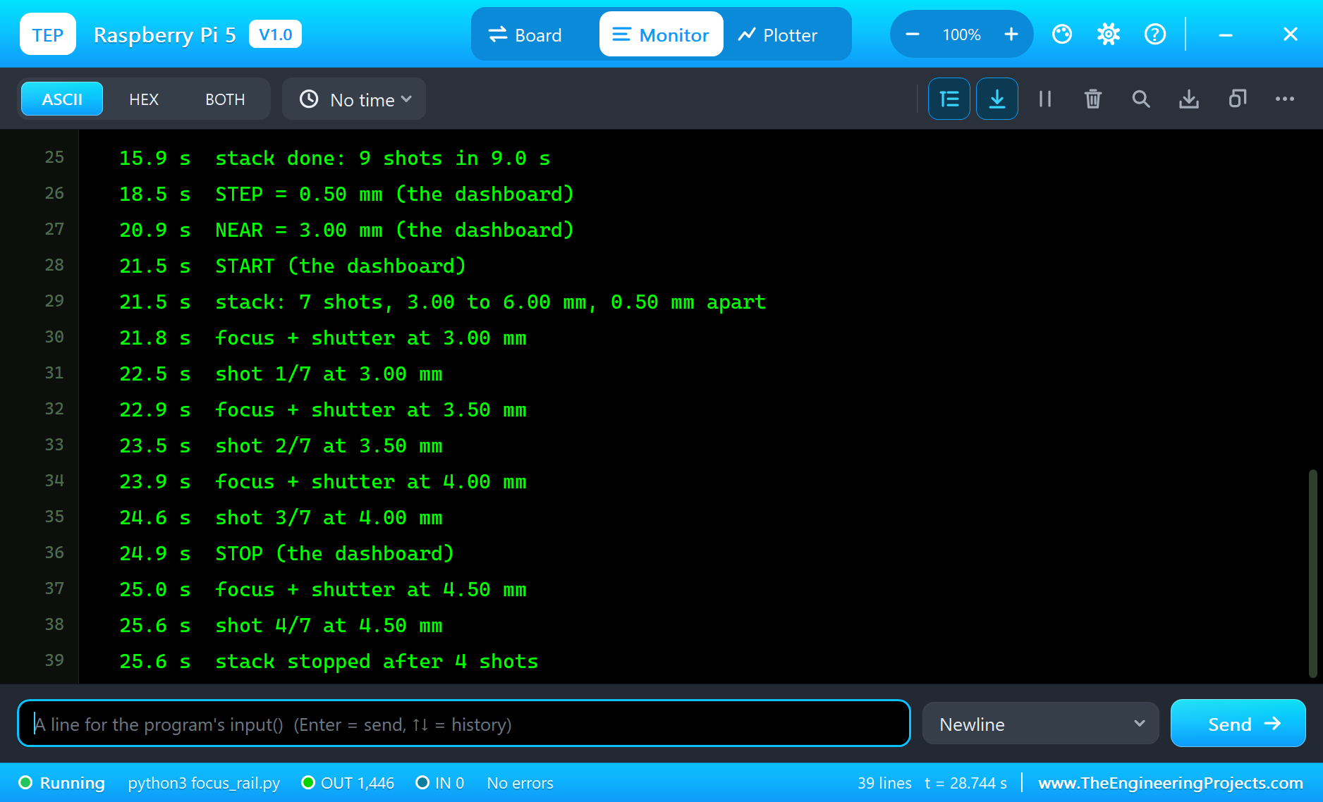
Here is the run that made the screenshots of this tutorial, 28.8 seconds of simulation. The times are the program's own, the seconds since it started, as it printed them in the Pi's terminal.
Homing
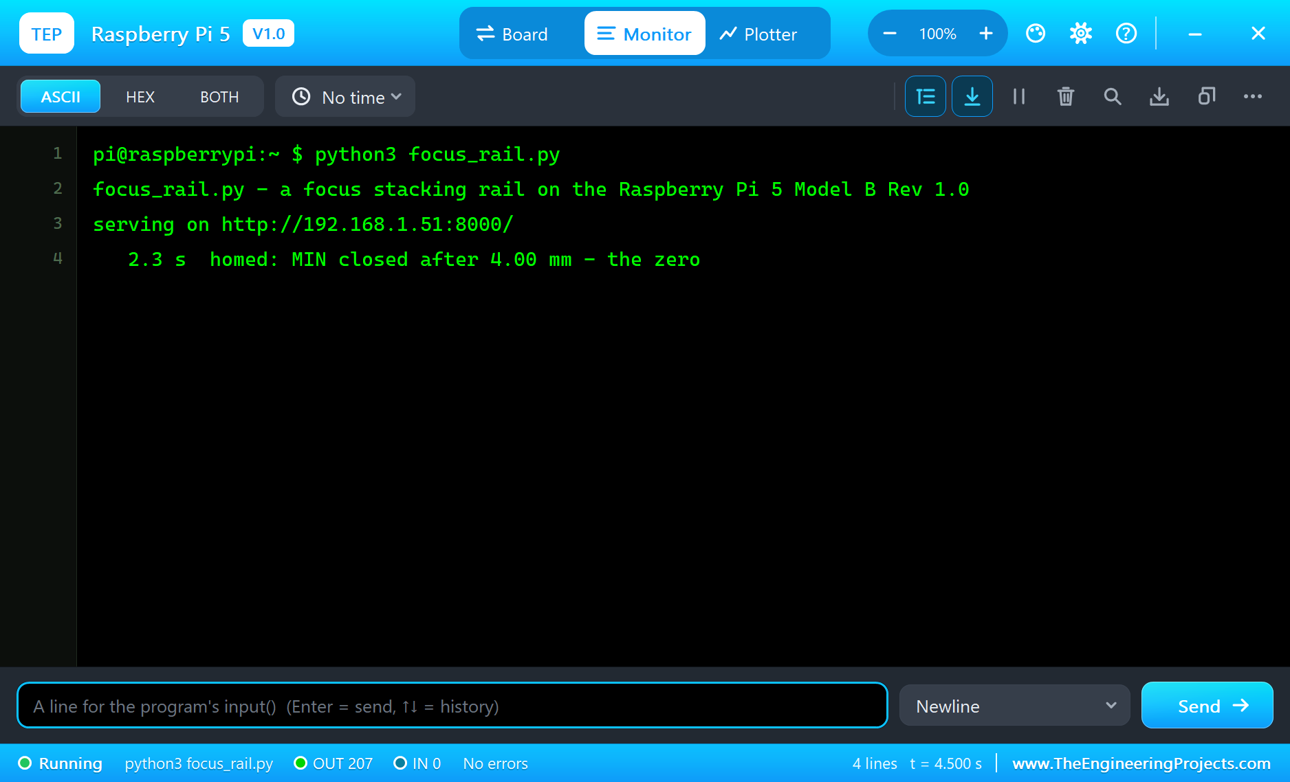
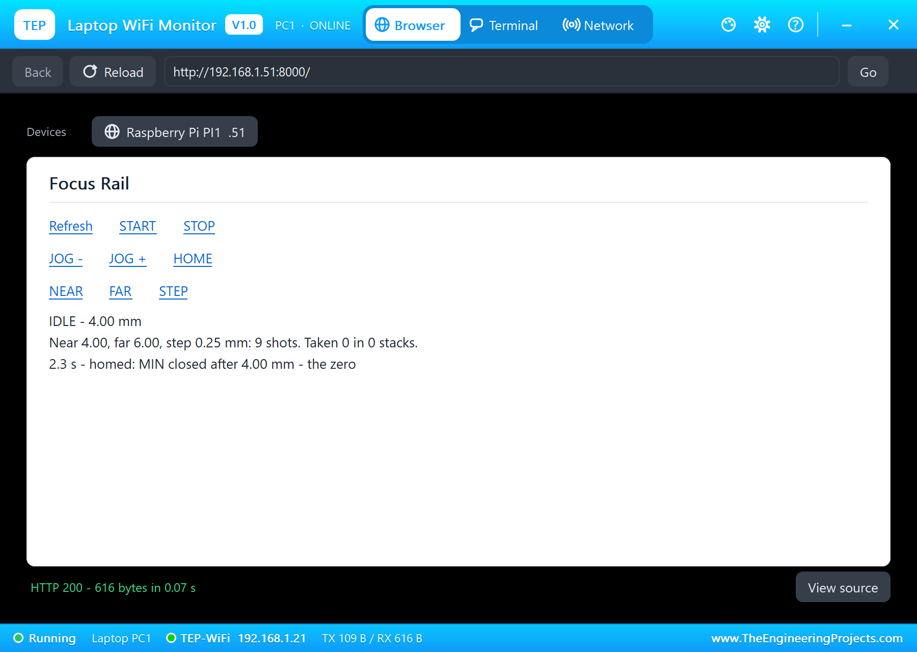
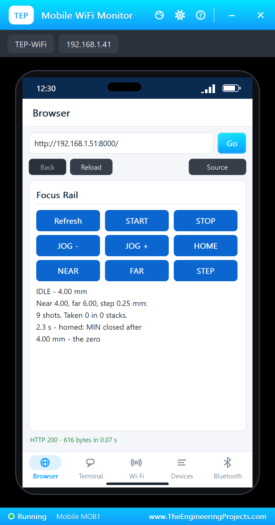
The carriage starts at 6 mm on the stage's own scale. As soon as the program runs it heads for MIN: the stage's pop-up catches it at 2.96 mm, moving towards MIN at 2.5 mm/s on average (3 mm/s inside each 0.2 mm bite) with 1.20 A in the coils. At 2.3 s the terminal prints "homed: MIN closed after 4.00 mm - the zero": MIN closes 2 mm from the end of the track, exactly where the model puts it. Then the rail moves out to NEAR, 4.00 mm from the zero, and the TMC2209 holds it there.
A Nine-Shot Stack
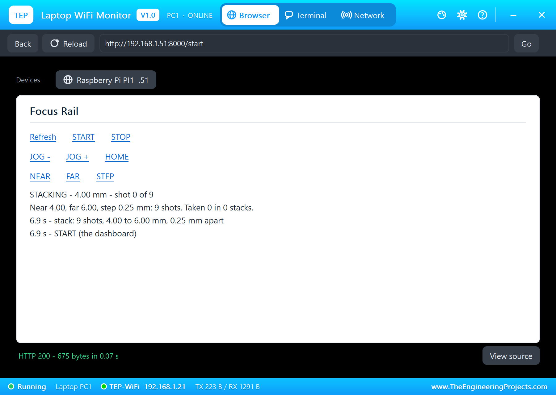
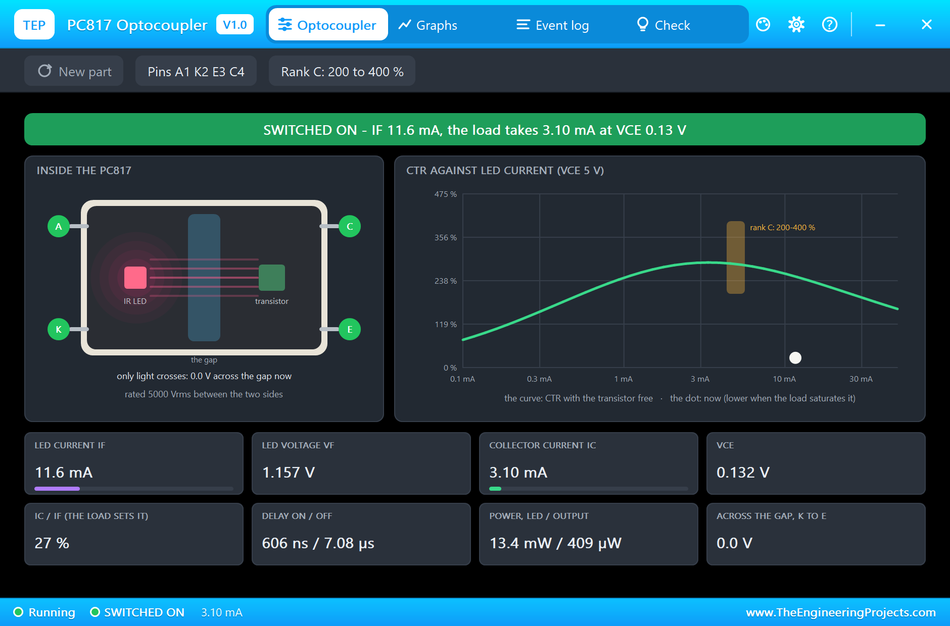
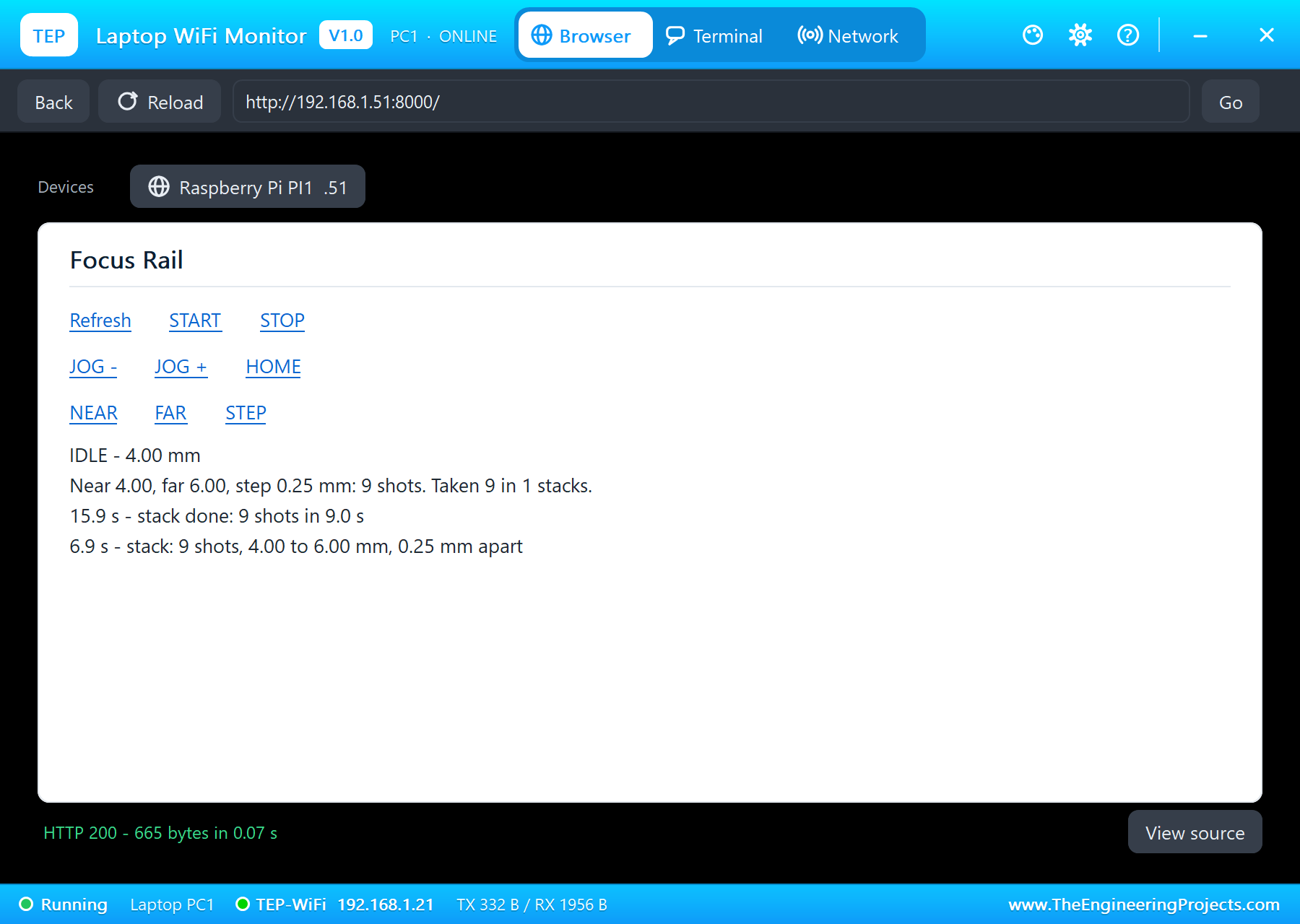
At 6.9 s START on the laptop begins "stack: 9 shots, 4.00 to 6.00 mm, 0.25 mm apart". Every second the rail moves 0.25 mm in 50 ms, settles for 0.3 s, and the program prints "focus + shutter at 4.50 mm" as it presses the camera's buttons. The run pauses during the third shot: both yellow LEDs are lit, the camera focused and its shutter pressed. The shutter PC817 is SWITCHED ON and its transistor takes 3.10 mA from the camera's line at only 0.13 V, a firm press. Its LED takes 11.6 mA in the simulation; the simulated GPIO drives it harder than a real Pi's 3.3 V pin, where it would be about 6.4 mA, and either is far inside the PC817's ratings. Between the moves the TMC2209 holds the motor at 1.20 A, standing still, at 32 C. At 15.9 s: "stack done: 9 shots in 9.0 s", and the rail returns to NEAR for the next one.
New Settings from the Phone, and STOP
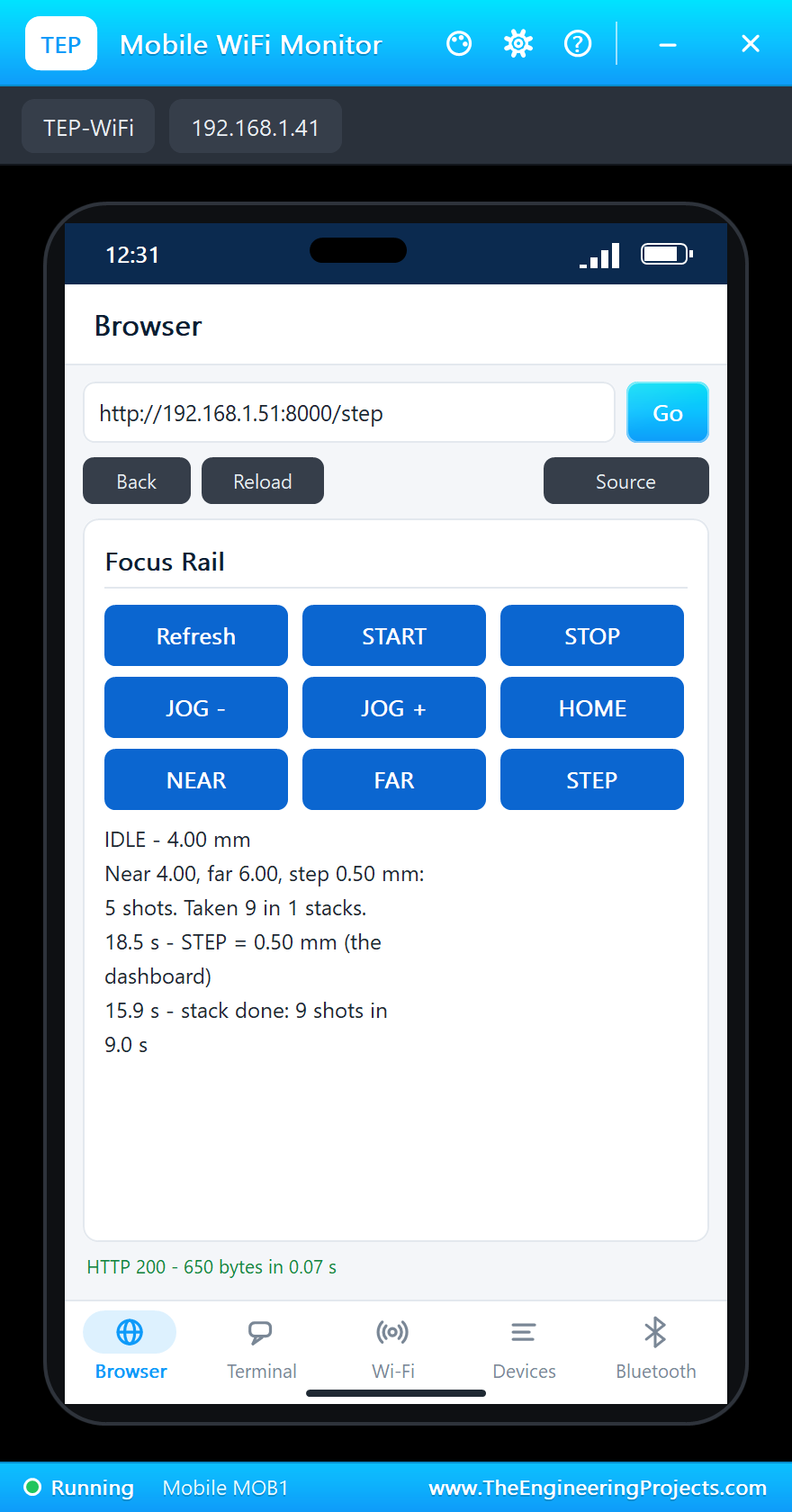
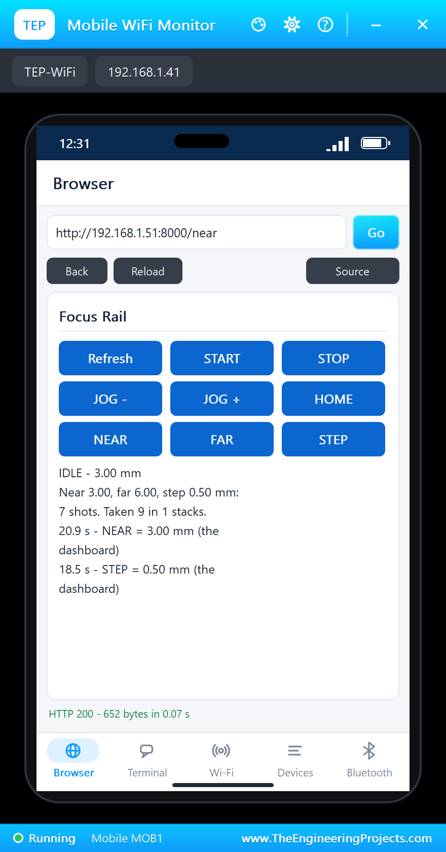
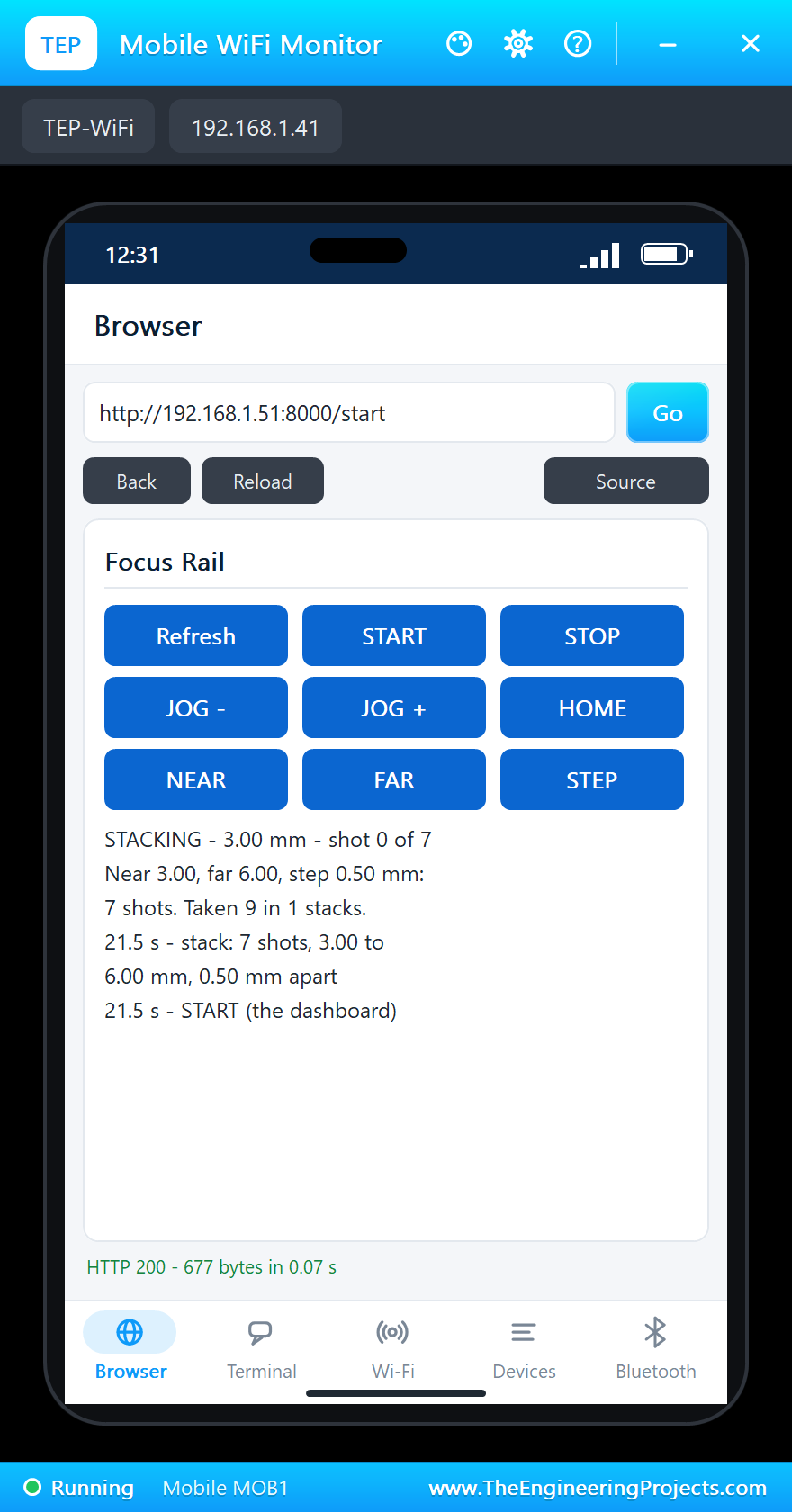
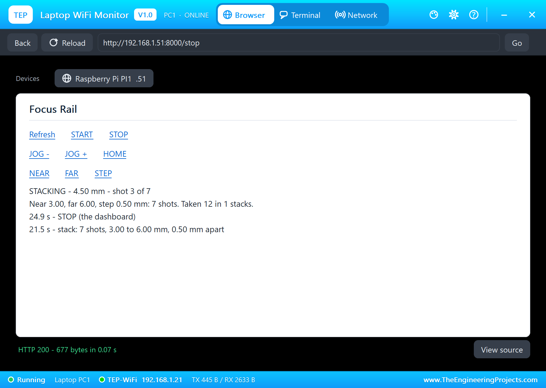
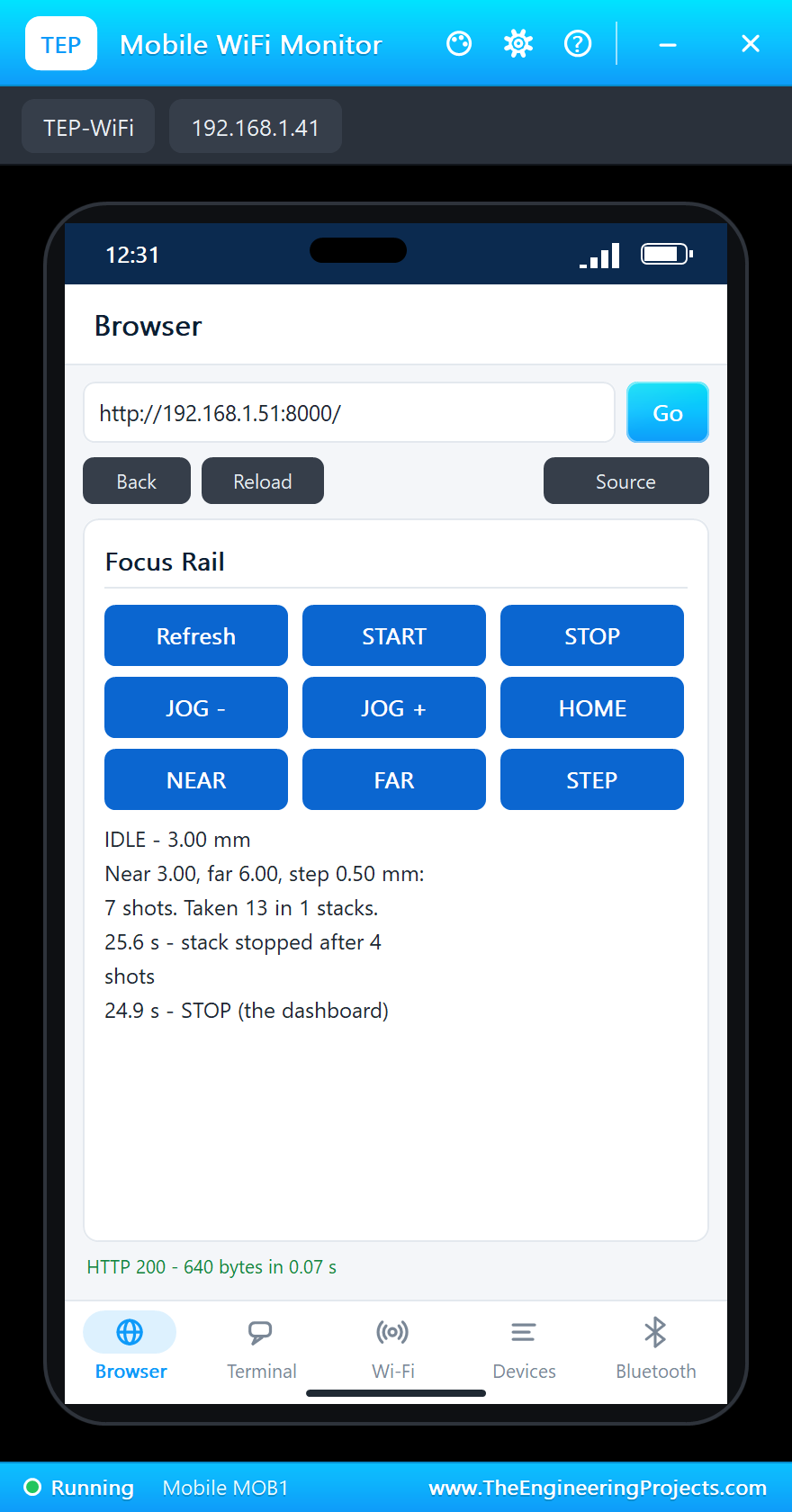
At 18.5 s STEP on the phone changes the step to 0.50 mm. JOG - twice moves the rail back 1 mm, and at 20.9 s NEAR takes the position: "NEAR = 3.00 mm". START at 21.5 s plans "7 shots, 3.00 to 6.00 mm, 0.50 mm apart". At 24.9 s STOP on the laptop arrives while the fourth shot is under way: the program lets that photo finish, never stopping the rail between the shutter and the end of the exposure, and then reports "stack stopped after 4 shots" and returns to NEAR.
The Numbers of the Run
| What | Result |
|---|---|
| Homing | MIN after 4.00 mm at 2.3 s |
| Stack 1 | 9 shots, 4.00 to 6.00 mm by 0.25 mm, in 9.0 s |
| A shot | FOCUS 0.15 s, SHUTTER 0.2 s; the PC817 3.10 mA at 0.13 V |
| Holding | 1.20 A at standstill, 32 C, no steps lost |
| Stack 2 | 7 planned at 0.50 mm from 3.00 mm; stopped after 4 |
| Simulation | 28.8 s of simulation |
Download the Project Files
Click the button below to download Focus-Stacking-Rail-Raspberry-Pi-5-Proteus-Simulation-v1.0.zip (about 14.3 MB, without the source code of the models):
Focus Stacking Rail on Raspberry Pi 5: Proteus Simulation Project V1.0- Proteus Simulation: Pi-5-Focus-Stacking-Rail.pdsprj, the program focus_rail.py and copies of the models.
- Python Code: focus_rail.py, the complete program.
- Proteus Library Files: the LIB files of the Raspberry Pi 5, the TMC2209, the linear stage, the optocouplers, the LED, the resistor and the two WiFi Monitors.
- Proteus Model Files: the DLL models and the TEPPi folder, the Python 3.11 and the runtime that the Pi board runs.
- README.txt: the installation steps, the properties, the test results and the links to every library post.
No Proteus yet? Read How to Download and Install Proteus 7 and 8. New to libraries? Follow How to Install a New Library in Proteus.
How to Install the Project Files
- Close Proteus and extract the whole zip file, for example to your Desktop.
- Copy the files from Proteus Library Files into the LIBRARY folder of Proteus.
- Copy everything in Proteus Model Files, the DLL files and the TEPPi folder, into the MODELS folder.
- Start Proteus and open the project from the Proteus Simulation folder.
Changing the Code
The program is plain Python 3: edit focus_rail.py beside the project and press Play again; the Pi board runs the new file. The speeds, the scale and the timings are at the top. The same program runs on a real Raspberry Pi 5 with Raspberry Pi OS and lgpio. For our other Raspberry Pi 5 project with stepper motors and homing on a sensor, see the Split-Flap Message Board with Raspberry Pi 5.
Ideas to Extend the Project
- Take up the lead screw's backlash: approach NEAR from the same side every time, overshooting by 0.5 mm and coming back.
- Add the camera's exposure time and a flash recycle delay to the dashboard.
- Ramp the speed up and down for heavy cameras, so the motor never loses steps.
- Use the TMC2209's UART to lower the holding current between moves and read its StallGuard load.
- Send the photos to a stacking program over the network when the stack is done.
- Add a second axis for focus bracketing across a wide subject.
From Simulation to Real Hardware
- Vibration: mount the rail on a heavy, stiff base and give the camera a longer settle time; at macro scale a footstep blurs a shot.
- The camera's connector: check your camera's remote pinout; most use a 2.5 mm jack (tip shutter, ring focus, sleeve ground) or a brand connector.
- Power: feed the TMC2209 from its own 12 V supply and keep VDD on the Pi's 3.3 V so the logic levels match.
- Set VREF: turn the TMC2209's trimmer for the current your motor needs, measuring VREF with a meter.
- Electronic shutter: use the camera's silent or electronic-first-curtain shutter so the shutter itself does not shake the shot.
Troubleshooting
- HOMING FAILED: MIN never closed - the switch or COM is not wired, or DIR moves away from MIN; swap A+ with A-.
- The rail moves the wrong way: swap A+ with A-, or invert DIR in the program.
- Lost steps: the stage's pop-up counts them; lower MOVE_HZ or raise VREF.
- The camera does not fire: the PC817's A and K swapped, or the camera's focus and shutter lines mixed up.
- The terminal cannot start Python: the TEPPi folder is not in MODELS.
Limitations of the Simulation
- The camera is two LEDs: the simulation shows when it would focus and fire, not the photos.
- The stage model has no backlash in its nut; a real T8 nut has a little unless it is an anti-backlash nut.
- The network is simulated: the dashboard travels between the Pi and the two monitors inside Proteus; the times in this tutorial are simulation time.
- Raspberry Pi is a trademark of Raspberry Pi Ltd; the TMC2209 is made by Analog Devices (Trinamic) and the PC817 by Sharp and others. This project is not made or endorsed by them or by Labcenter.
So, that was all about the Focus Stacking Rail on Raspberry Pi 5: Proteus Simulation Project. I hope it helps you build your own rail: a depth of field that tells you the step, a lead screw and microstepping that give 5 microns a pulse, a homing routine that finds a repeatable zero, and optocouplers that press the camera's buttons without touching its electronics, all tested in a simulation before you mount a camera on a single real rail. More IoT projects with the ESP32 and the Raspberry Pi 5 are coming in this series. If you have any questions, ask in the comments and I will help you out. Till the next tutorial, take care and have fun!

Comments
0