


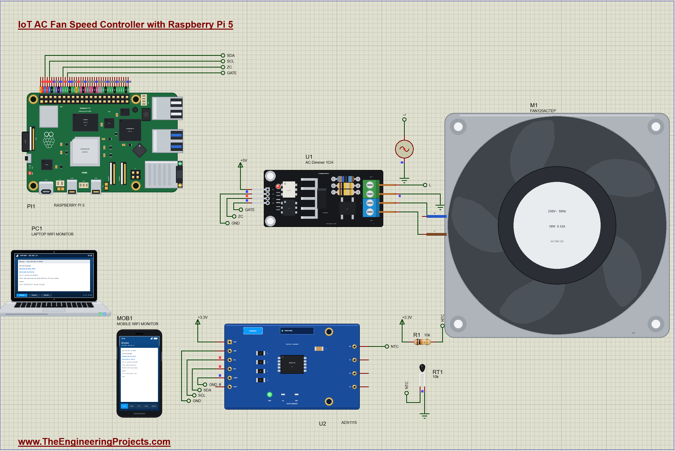
IoT AC Fan Speed Controller with Raspberry Pi 5 - Proteus Simulation


Hello friends, I hope you all are doing great. Today, I am going to share the IoT AC Fan Speed Controller with Raspberry Pi 5 - Proteus Simulation, the thirty-second project of our IoT Projects series. If you have searched for a Proteus simulation of a Raspberry Pi controlling an AC fan with a triac dimmer, here is a complete one. A Raspberry Pi 5 sets the speed of a 120 mm 230 V AC fan by phase-angle control through an AC dimmer module, measures the mains frequency from the dimmer's zero-cross pulses, reads the room's temperature from an NTC thermistor through an ADS1115, speeds the fan up as the room warms, and serves a live web dashboard that you can open on a laptop or a phone.
A PWM pin can dim an LED or slow a DC motor, but an AC fan runs straight from the mains, and there the trick is different: you cannot chop 230 V with a transistor at a few kilohertz, so you choose the moment in each half cycle at which a triac switches the mains on. In this tutorial, we will go through the circuit, learn how a zero-cross detector and a triac work together, why a fan needs a longer gate pulse than a lamp, how to turn a power level into a firing delay, how an NTC thermistor and an ADS1115 measure the temperature, walk through the Python program, and then run the simulation: the fan off in a cool room, starting by itself as the air warms, fixed speeds from the dashboard, and slowing down again as the room cools. At the end, you can download the project with the program, every library file and the Python runtime the Pi needs.
NOTICE: Our team has put a lot of effort into this project: the circuit, the code and every part in the simulation are our own work, and you get them all free. Your feedback is the fuel that keeps us going, so please tell us what you think in the comments below. And if our free projects help you, you can buy us a coffee. So, let's get started with the IoT AC Fan Speed Controller with Raspberry Pi 5 - Proteus Simulation:
What Does This AC Fan Controller Do?
- Controls a mains fan: a 120 mm 230 V AC fan through an AC dimmer module, by phase-angle control.
- Finds every zero of the mains: the dimmer's zero-cross pulse, 100 times a second at 50 Hz, on GPIO17.
- Fires the triac at the right moment: a delay after each zero that gives the power asked, from GPIO27.
- Measures the mains: the frequency from the time between zero crosses.
- Reads the temperature: a 10 k NTC thermistor in a divider, read by an ADS1115, because the Pi has no analog input.
- AUTO mode: off below 24 degrees C, 30 % at 24 degrees, rising to 100 % at 36 degrees.
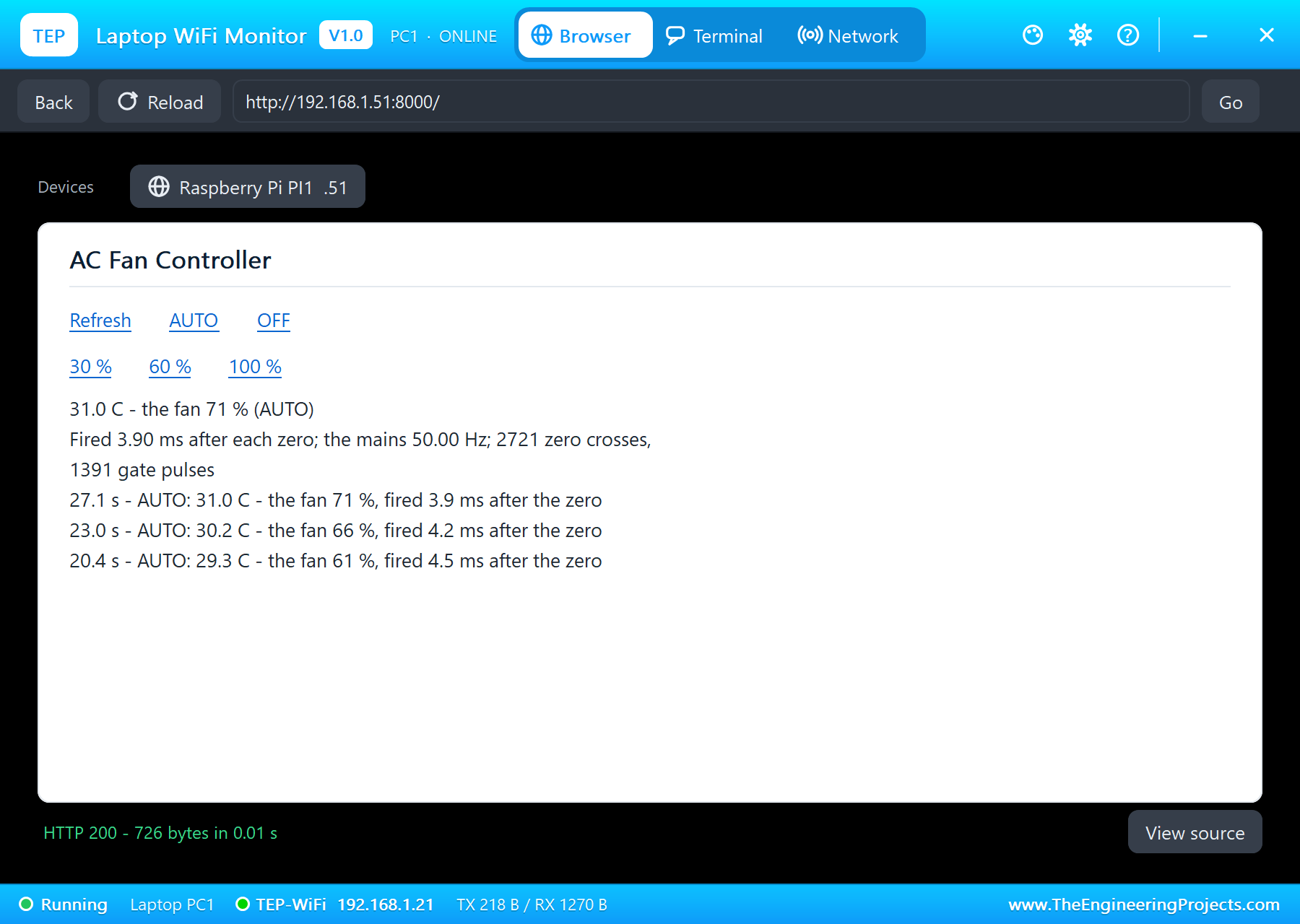
- A dashboard: AUTO, OFF, 30 %, 60 % and 100 % from a laptop or a phone, with the temperature, the firing delay and the mains.
It is a great project for learning how mains loads are controlled, how timing matters in an embedded program, and how to measure temperature with an NTC. In the simulation, the mains comes from Proteus's own AC source, and the NTC's pop-up warms and cools the air around the bead.
Components Used in the Proteus Simulation
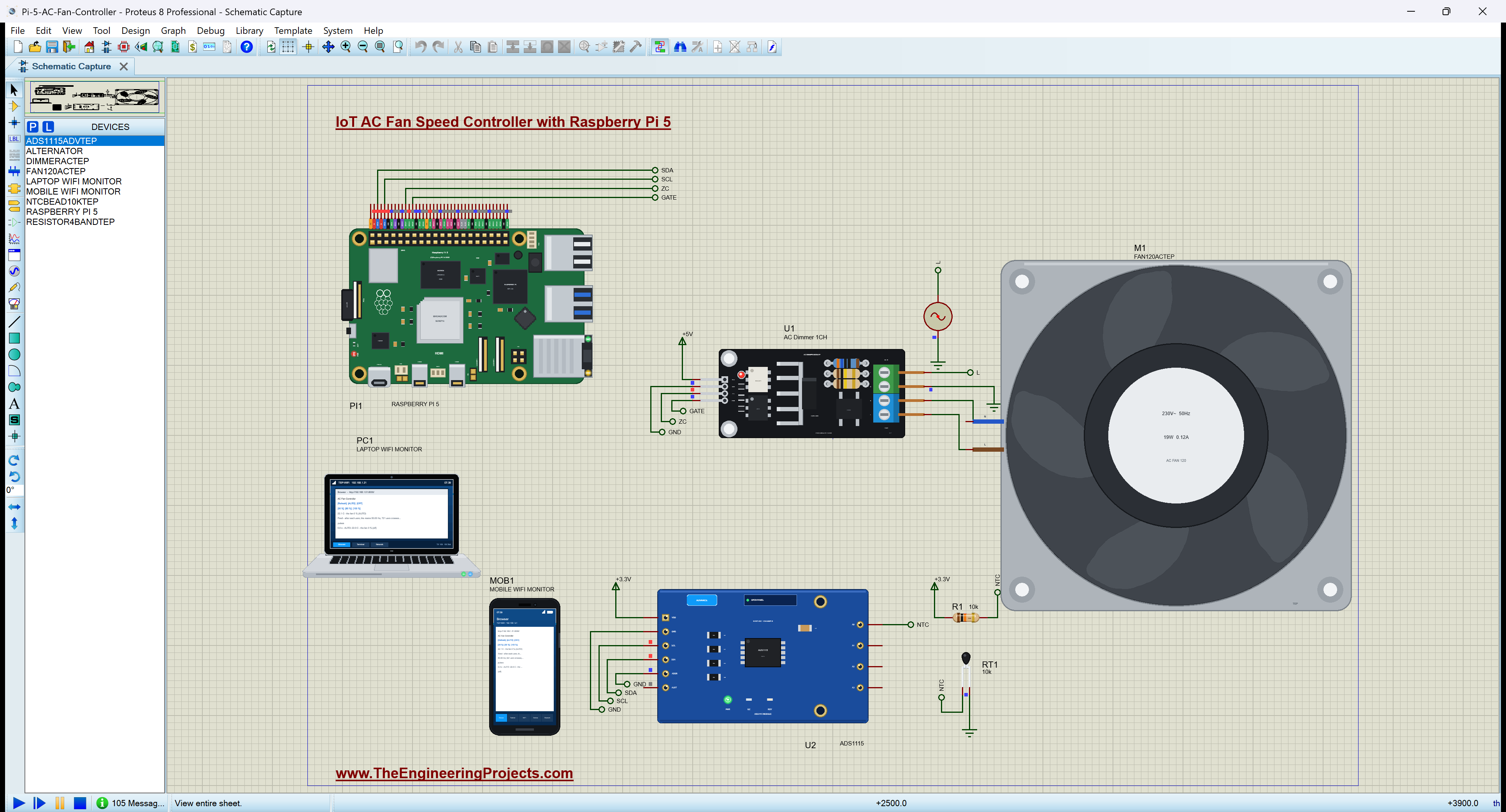
All the TEP parts come from our Proteus libraries, each with its own tutorial. The project zip at the end includes every LIB and DLL file.
| Part | Proteus device | Library post | Connection |
|---|---|---|---|
| Raspberry Pi 5 | RASPBERRY PI 5 | Raspberry Pi 5 Library for Proteus | PI1, Ethernet 192.168.1.51 |
| AC dimmer module (BTA16 triac, zero-cross) | DIMMERACTEP | AC Dimmer Module Library for Proteus | U1, Z-C GPIO17, PWM GPIO27 |
| 120 mm 230 V AC fan | FAN120ACTEP | 120mm 230V AC Fan Library for Proteus | M1, on the dimmer's LOAD |
| NTC thermistor 10 k, B 3950 | NTCBEAD10KTEP | NTC Thermistor Library for Proteus | RT1, with R1 10 k |
| ADS1115 16-bit ADC | ADS1115ADVTEP | ADS1115 ADC Library for Proteus | U2, I2C1 at 0x48, A0 |
| Resistor 10 k | RESISTOR4BANDTEP | Resistor Library for Proteus | R1, the divider |
| 230 V 50 Hz mains | ALTERNATOR (Proteus) | - | V1, 325 V peak |
| Laptop WiFi Monitor | LAPTOP WIFI MONITOR | Laptop WiFi Monitor | PC1 |
| Mobile WiFi Monitor | MOBILE WIFI MONITOR | Mobile WiFi Monitor | MOB1 |
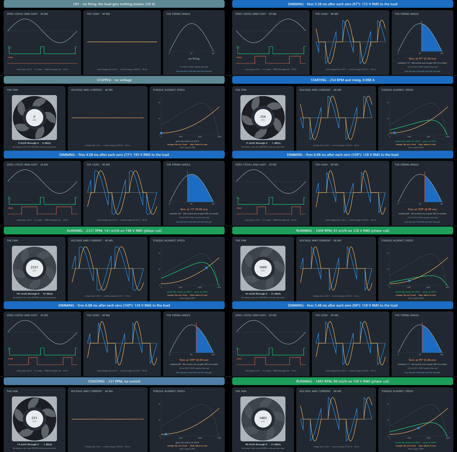
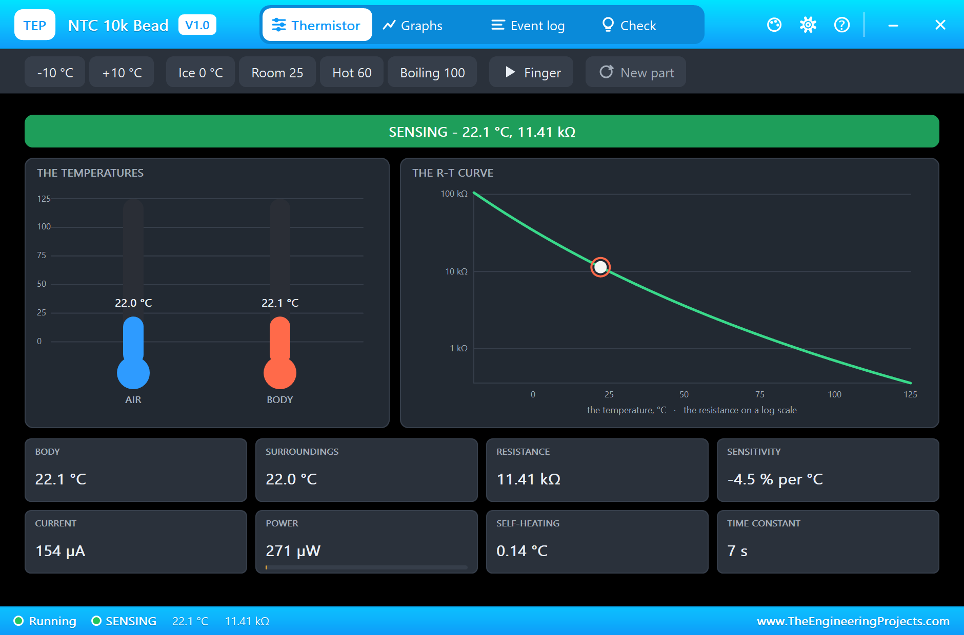
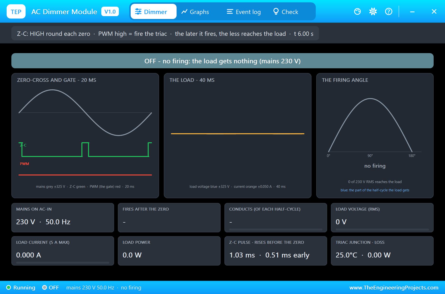
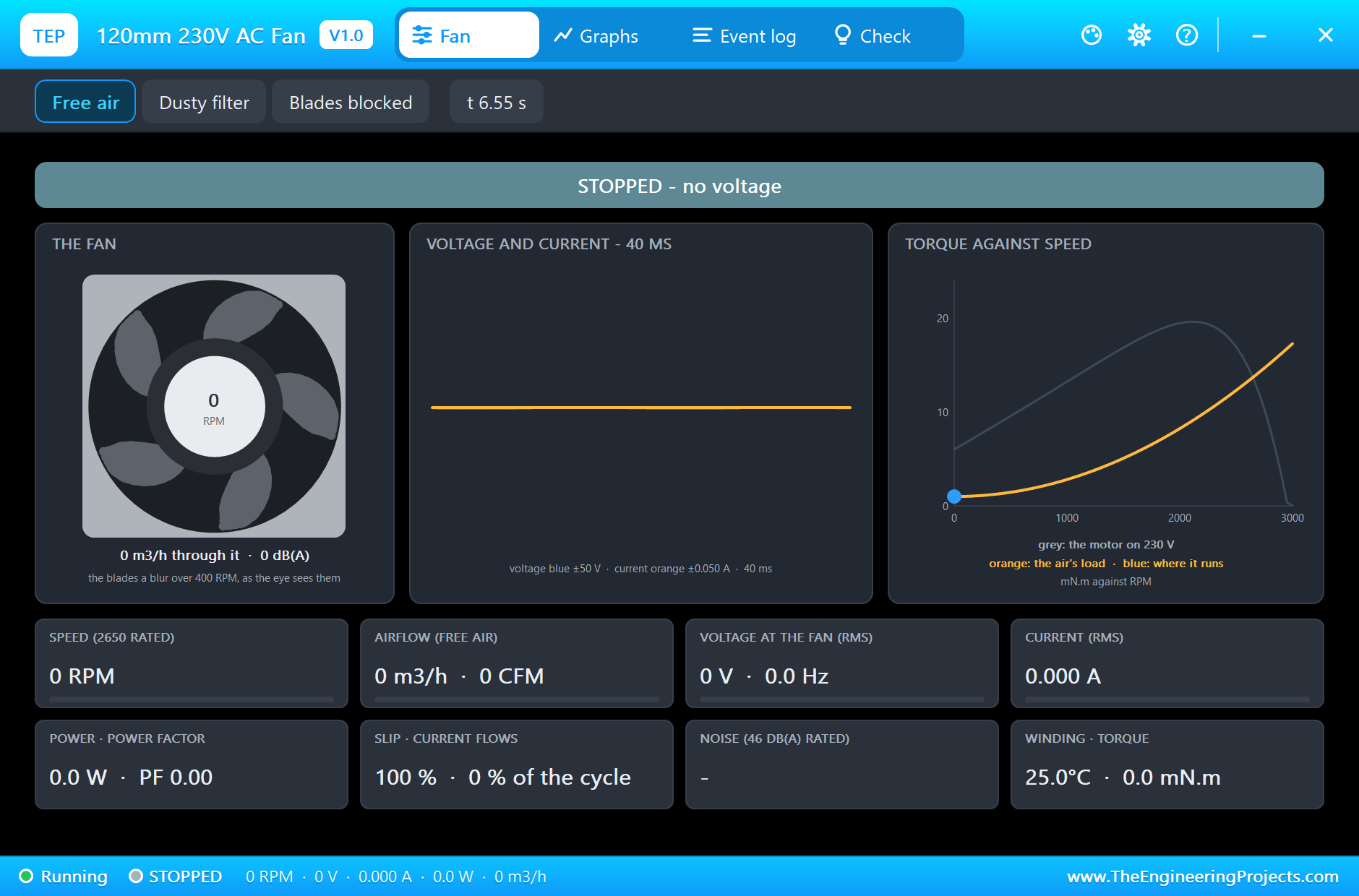
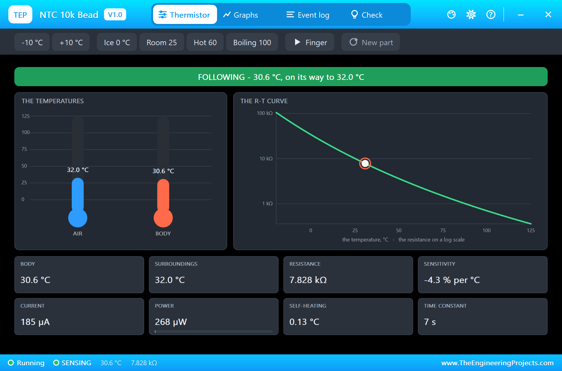
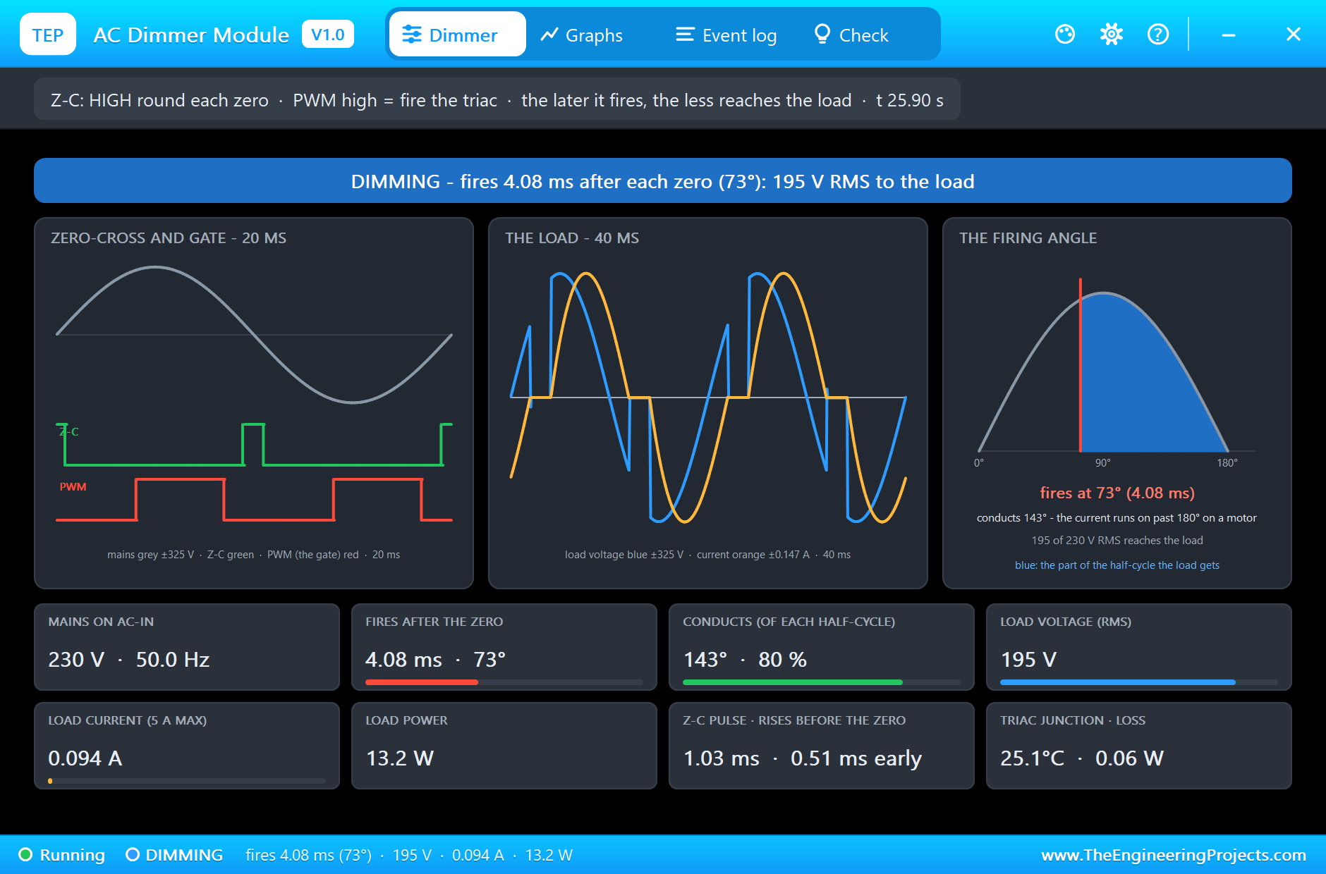
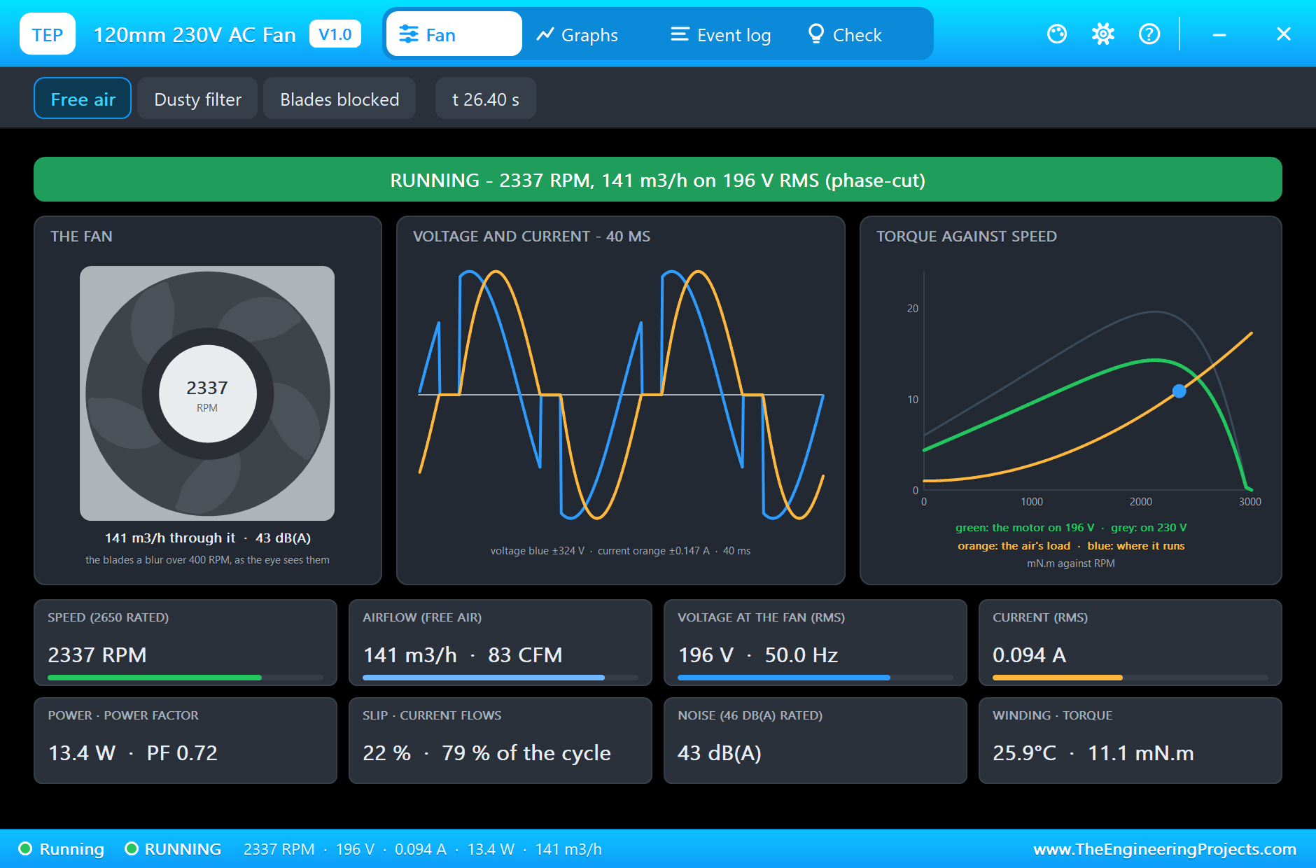
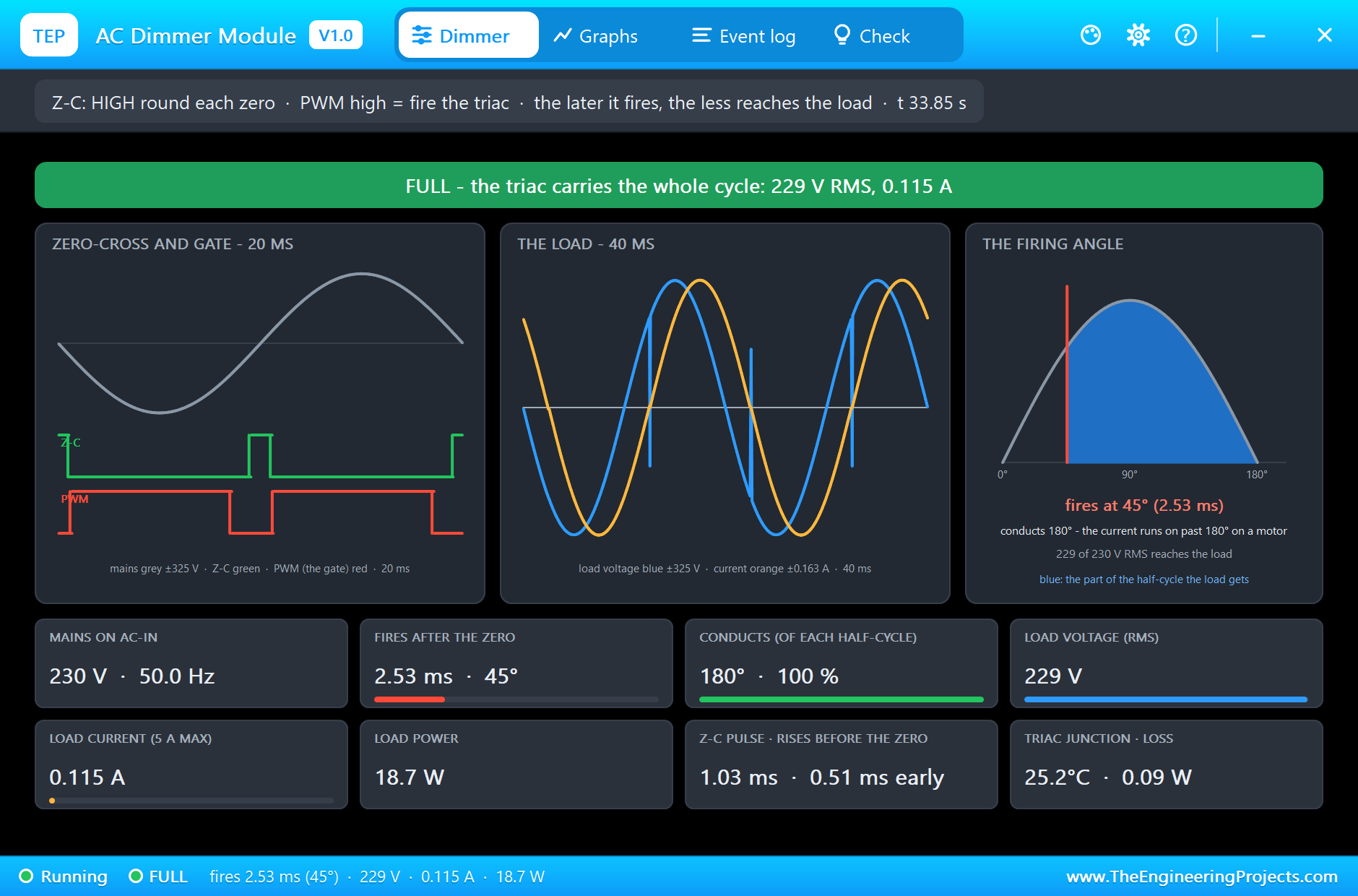
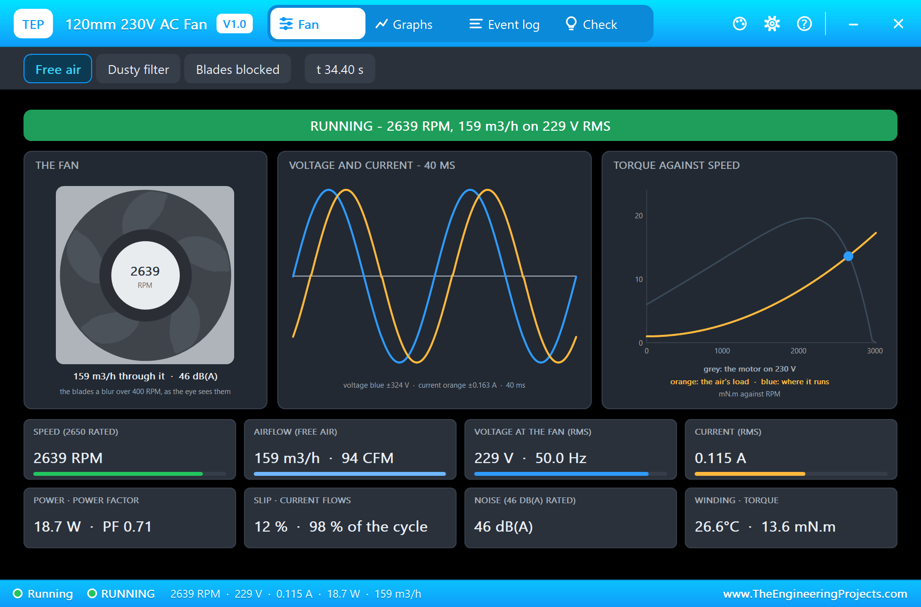
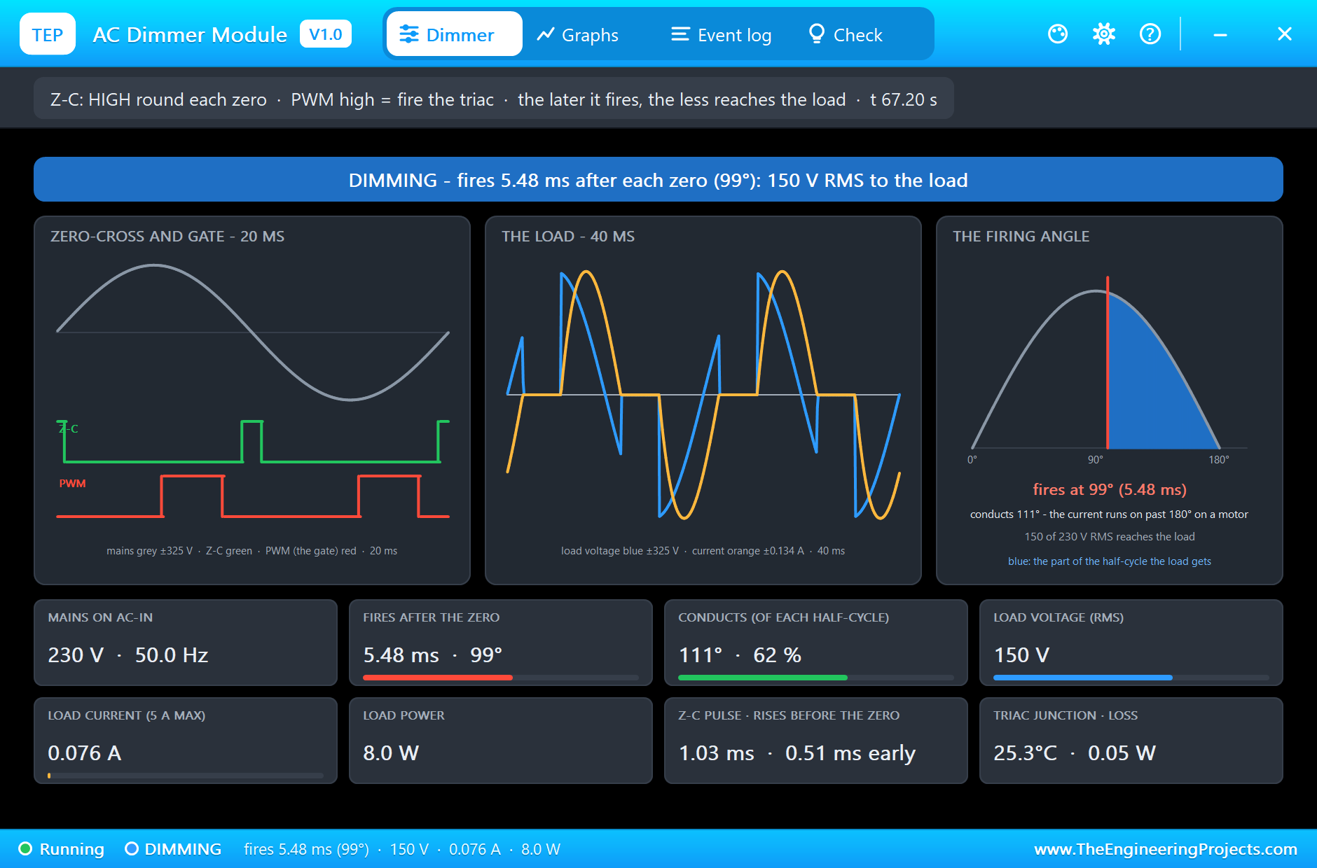
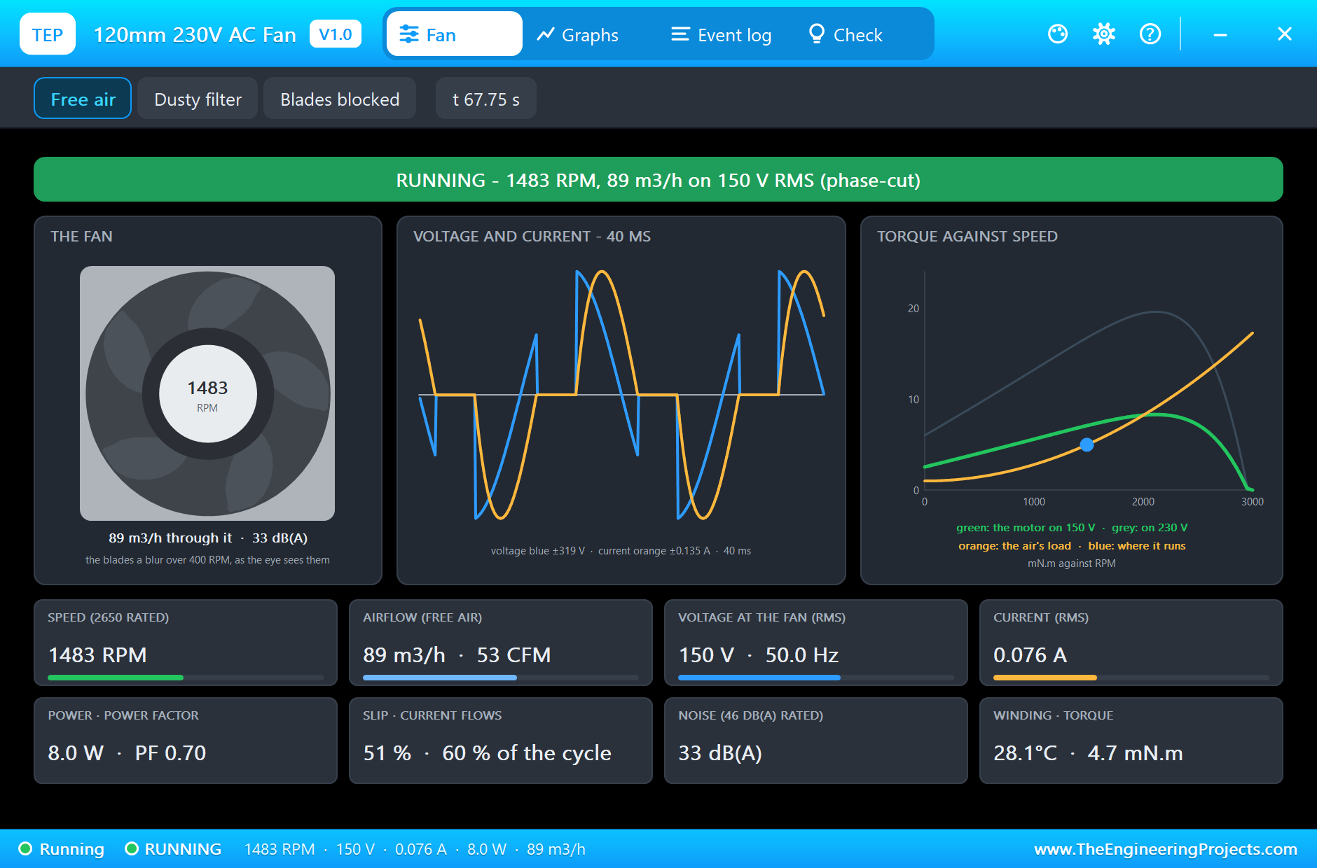
The dimmer, the fan, the NTC and the ADS1115 are models with pop-ups. The dimmer's pop-up shows the zero-cross pulses and the gate under the mains on a 20 ms scope, the fan's voltage and current, the firing angle and the triac. The fan's pop-up shows its blades turning, its speed, current and power, and its torque curve. The NTC's pop-up shows the air and the bead as two thermometers and sets the air: plus or minus 10 degrees, room, hot or a finger on the bead.
Proteus Simulation of the AC Fan Controller: the Circuit
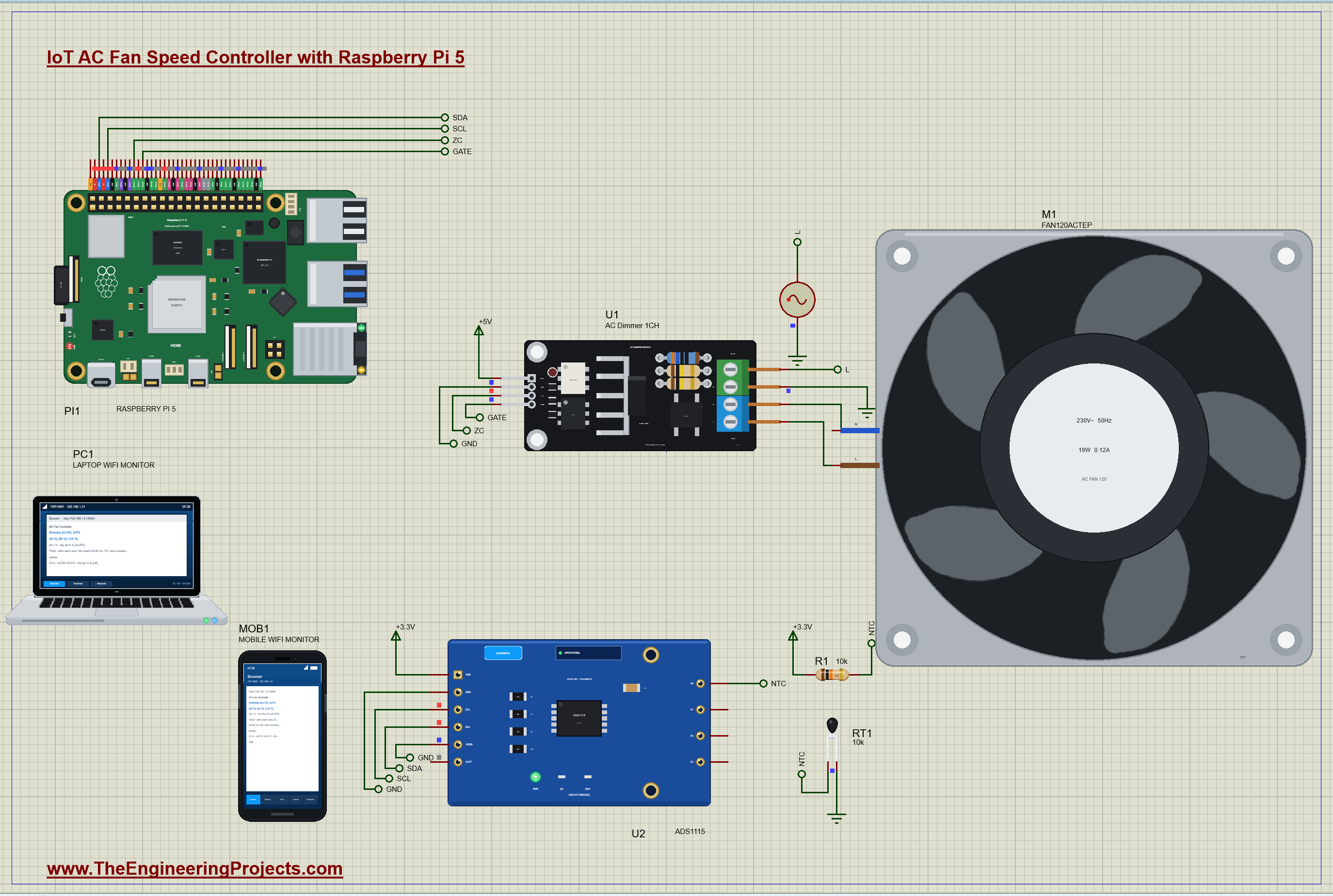
| Part | Pins | Raspberry Pi 5 header / other |
|---|---|---|
| U1 AC dimmer | VCC / GND / Z-C / PWM | +5V / GND / GPIO17 (pin 11) / GPIO27 (pin 13) |
| U1 AC dimmer | L-IN / N-IN / L-OUT / N-OUT | the mains' L / the earthed neutral / the fan's L / the fan's N |
| V1 alternator | + / - | L / ground (the earthed neutral) |
| U2 ADS1115 | VDD / GND / SDA / SCL / ADDR / A0 | +3.3V / GND / GPIO2 (pin 3) / GPIO3 (pin 5) / GND (0x48) / NTC |
| R1, RT1 | the divider | +3.3V - R1 10 k - NTC - RT1 - GND |
The dimmer module keeps the mains away from the Pi: its two optocouplers carry the zero-cross signal out and the firing signal in, so the logic header shares nothing with the 230 V side. The NTC and R1 form a divider across 3.3 V; the ADS1115 measures the middle, and the program turns the voltage into the NTC's resistance and then into a temperature.
How the AC Fan Controller Works
The Zero-Cross Detector
The mains is a sine wave: at 50 Hz it passes through zero 100 times a second, every 10 milliseconds. To switch it at a chosen point in each half cycle, the Pi must know where each half cycle starts. The dimmer's zero-cross detector does that: a bridge rectifier and two 100 kohm resistors light the LED of an optocoupler from the mains, and its transistor pulls the Z-C pin low whenever the mains is well away from zero. Near each zero there is not enough voltage to light the LED, the pull-up wins, and Z-C gives a short high pulse, about 1 millisecond wide. The true zero is the middle of the pulse, so the pulse rises about half a millisecond before it: the dimmer's library measured 0.51 ms. The program adds that half millisecond to every delay.
The Triac and Phase-Angle Control
A triac is a switch for AC: a small current into its gate turns it on, and it then stays on by itself until the current through it falls to zero, which on the mains happens at the end of each half cycle. So the triac cannot be switched off in the middle, but it can be switched on at any moment. Fire it 1 millisecond after the zero and the fan gets almost the whole half cycle; fire it 8 milliseconds after the zero and it gets only the last 2 milliseconds. That is phase-angle control, the way a light dimmer works. On the module, the PWM pin lights the LED of a MOC3021 opto-triac, which feeds the gate of a BTA16 triac rated 16 A and 600 V.
Worked example: the share of a half sine's energy that comes after the firing angle a (0 to pi) is 1 - a/pi + sin(2a)/(2 pi). Fire at 5 ms, the middle of the half cycle (a = pi/2), and the load gets exactly 50 % of the power, 163 V RMS from the 230 V mains. For 30 %, the program solves the formula backwards and fires at about 6 ms; for full power, it fires at 0.6 ms, as early as it safely can.
Why a Fan Needs a Long Gate Pulse
A lamp is a resistor: its current follows the voltage. A fan is a motor, an inductor, and its current lags behind the voltage: when the mains passes through zero, the current of the last half cycle is still flowing for a millisecond or two. If the gate pulse comes during that time, the triac is already on, the pulse does nothing, and when the current finally dies the triac switches off and stays off for the rest of the half cycle: the fan misses a half cycle and stutters. The cure is to hold the gate high from the firing moment until 8.5 ms after the zero, as the dimmer's library demo does. Whenever the triac can turn on during that window, it does.
Measuring Temperature with an NTC
An NTC thermistor is a resistor whose resistance falls as it warms: our 10 k bead has 10 kohm at 25 degrees C and loses about 4.5 % per degree. With R1 10 k from 3.3 V and the NTC to ground, the middle of the divider is 1.65 V at 25 degrees. The program reads it, works out the resistance with R = 10 k x V / (3.3 - V), and then the temperature with the Beta equation: 1/T = 1/298.15 + ln(R/10 k)/3950, with T in kelvin. Worked example from our run: 1.756 V means 11.37 kohm, and the equation gives 22.1 degrees C.
The Raspberry Pi has no analog input, so the ADS1115 measures the voltage: a 16-bit converter on I2C. The program starts a single conversion of A0 against ground on the plus or minus 4.096 V range, waits 10 ms and reads the result: one count is 125 microvolts.
The Python Code Explained
The whole program is included in the download. It uses lgpio for the GPIO pins, the zero-cross callback and the I2C bus, the math module, threads for the firing and the control loop, and the standard library's http.server for the dashboard. At the top are the pins and the timings:
ZC, GATE = 17, 27 # BCM numbersZC_EARLY_US = 510 # the Z-C pulse starts about half a millisecond before the real zero
GATE_END_US = 8500 # the gate held to 8.5 ms after the zero: a fan's current lags the voltageMIN_DELAY_US, MAX_DELAY_US = 600, 9000 # never fire right at the zero, never past the end of the half cycle
T_ON, T_FULL = 24.0, 36.0 # AUTO: off below T_ON, 30 % at T_ON, 100 % at T_FULLThe Firing Delay
delay_for() solves the energy formula for the firing angle by bisection, 30 halvings, and turns the angle into microseconds after the zero:
share = 1 - a / math.pi + math.sin(2 * a) / (2 * math.pi) return int(min(MAX_DELAY_US, max(MIN_DELAY_US, a / math.pi * HALF_US)))The Zero Cross and the Firing
lgpio calls on_zc() on every rising edge of the Z-C pulse. It measures the time since the last one, keeps a smoothed mains frequency, and wakes the firing thread:
lgpio.callback(chip, ZC, lgpio.RISING_EDGE, on_zc) s['hz'] = 0.5 / dt if s['hz'] is None else s['hz'] * 0.9 + 0.5 / dt * 0.1The firing thread waits for that wake-up, sleeps until the firing moment, raises the gate and holds it to 8.5 ms after the zero:
        time.sleep((ZC_EARLY_US + d) / 1e6)
        lgpio.gpio_write(chip, GATE, 1)              # the triac fires once its current can flow (after the fan's lagging current)
        time.sleep(max(GATE_MIN_US, GATE_END_US - d) / 1e6)
        lgpio.gpio_write(chip, GATE, 0)              # released before the next zero: it then stays on by itself to the zero
The Temperature and AUTO
lgpio.i2c_write_i2c_block_data(self.h, 0x01, [0xC3, 0x83]) # start, AIN0 vs GND, +-4.096 V, single shot, 128 SPS r = R_FIXED * v / (3.3 - v)
return 1 / (1 / 298.15 + math.log(r / R25) / BETA) - 273.15Twice a second, the control loop reads the temperature and sets the power: in AUTO from the temperature, otherwise the fixed level of the mode:
p = min(1.0, 0.3 + 0.7 * (temp - T_ON) / (T_FULL - T_ON)) p = {'OFF': 0.0, '30 %': 0.3, '60 %': 0.6, '100 %': 1.0}[mode]The pages are / (the dashboard), /auto, /off, /p30, /p60 and /p100 (the modes) and /data (JSON). The dashboard puts its six links first and stays short, because the WiFi Monitors show one screen of a page.
How to Run the Proteus Simulation
- Download the project zip below and install the library files and the TEPPi folder (the steps are under the download button).
- Open Pi-5-AC-Fan-Controller.pdsprj from the Proteus Simulation folder. Keep ac_fan.py and the DLL files next to it.
- Press Play. The NTC starts at 22 degrees C, so AUTO keeps the fan off.
- Click a lead of RT1 for the NTC's pop-up and press +10 C: the bead warms and the fan starts.
- Open the Laptop WiFi Monitor (PC1) or the Mobile WiFi Monitor (MOB1), press Go and try 30 %, 100 %, OFF and AUTO.
- Click the dimmer and the fan for their pop-ups and watch the firing angle and the speed.
Simulation Results: the AC Fan Controller in Proteus
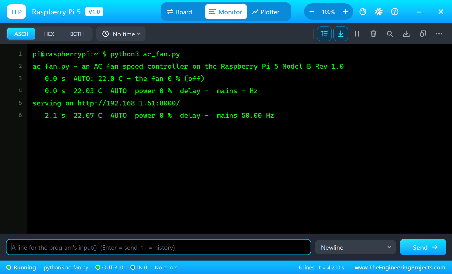
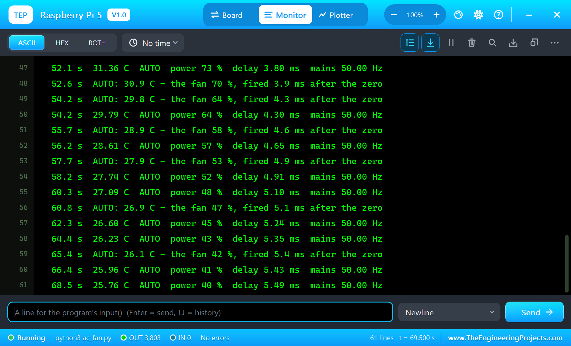
Here is the run that made the screenshots of this tutorial, 69.6 seconds of simulation. The times are the program's own, the seconds since it started, as it printed them in the Pi's terminal; the volts, amps and speeds come from the dimmer's and the fan's pop-ups.
A Cool Room: the Fan Off
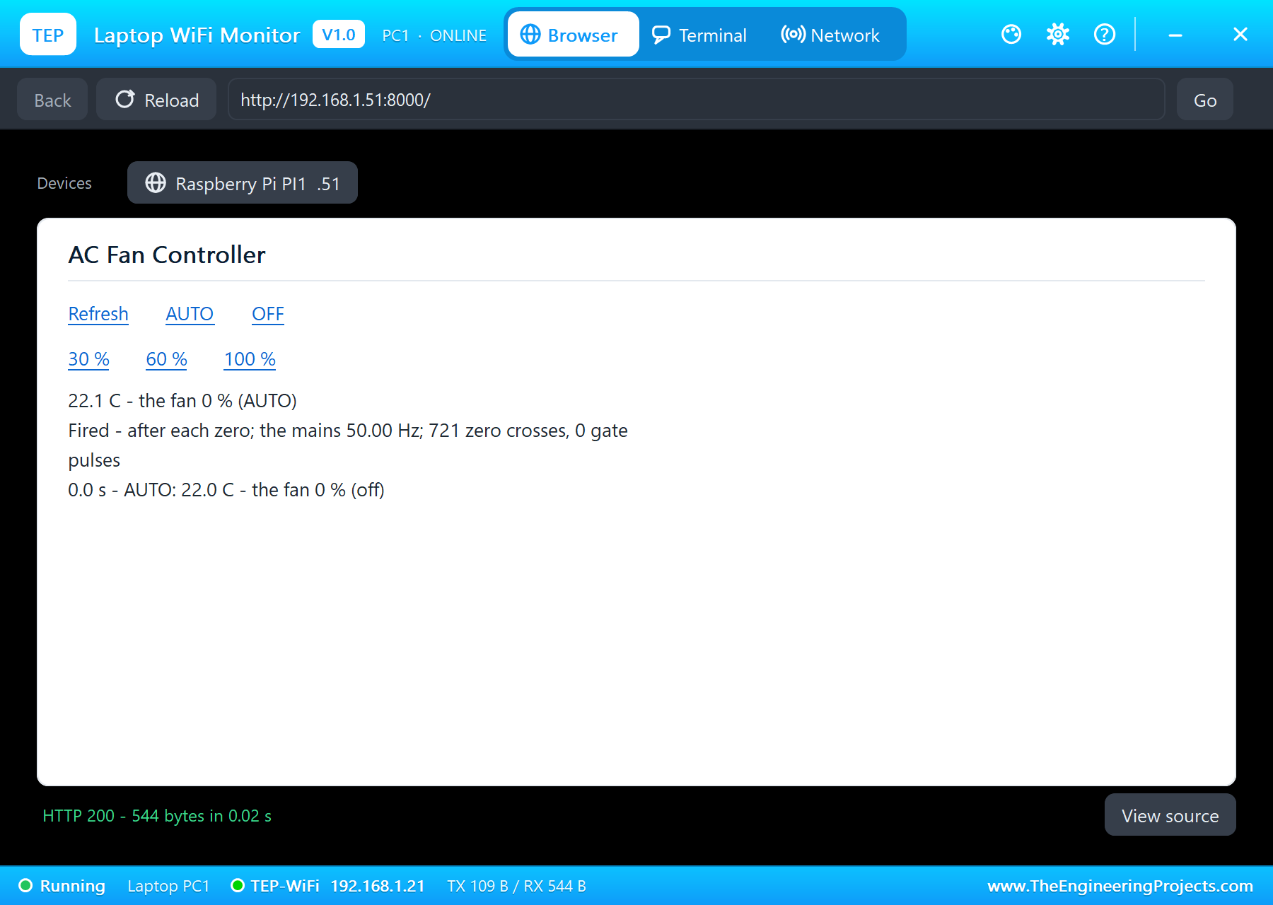
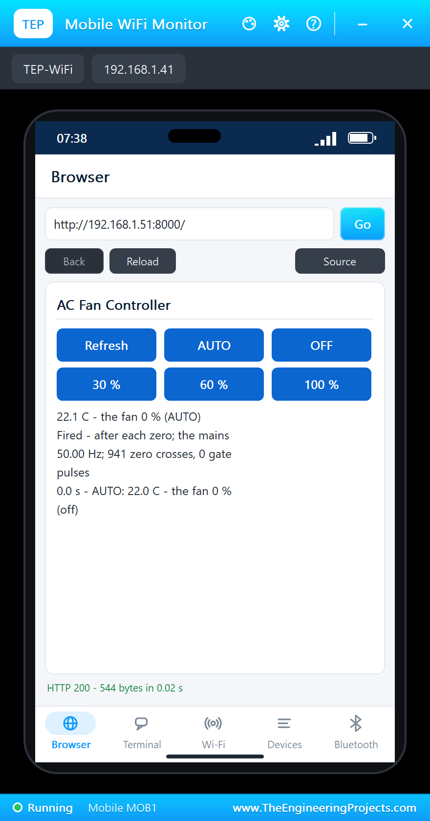
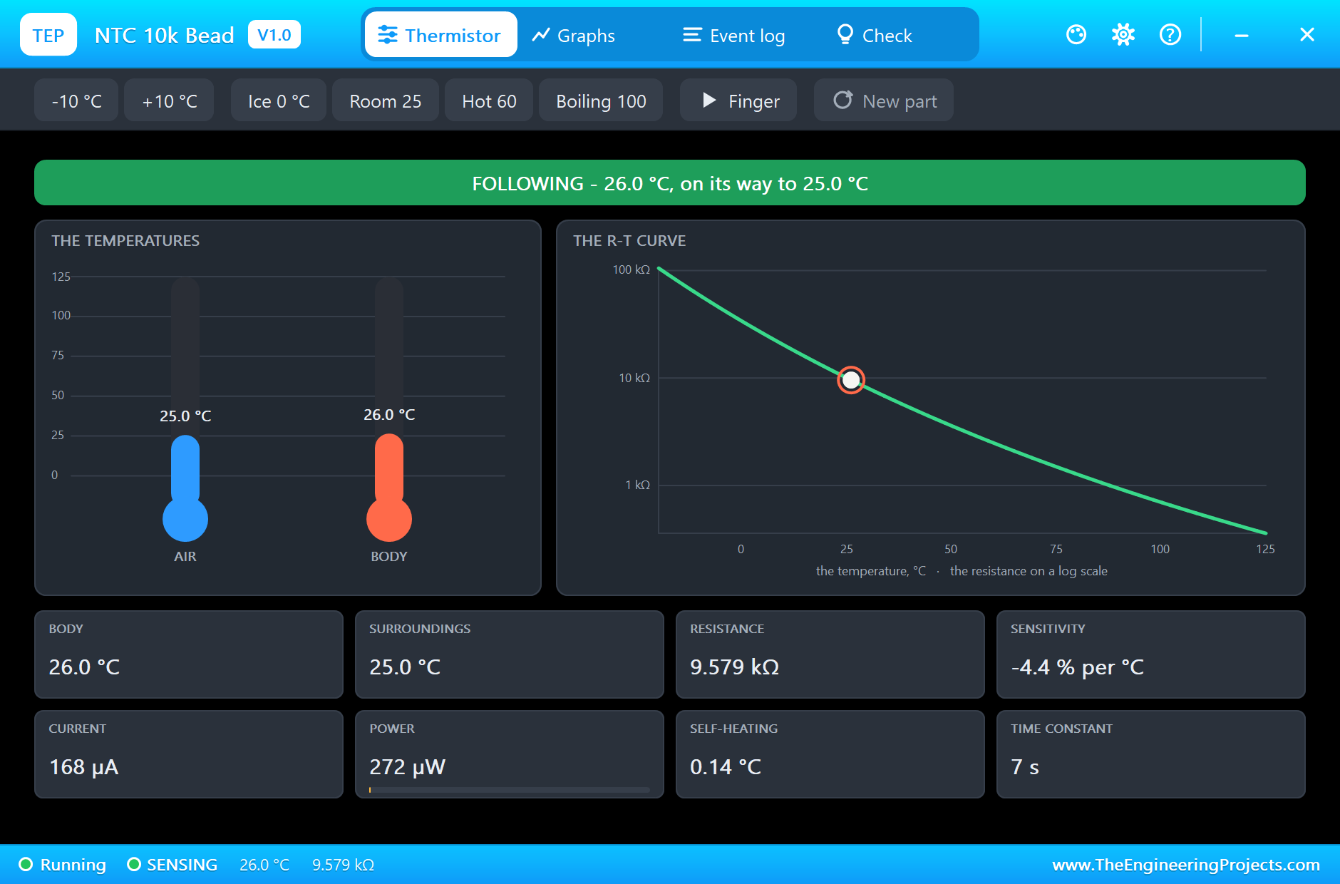
The NTC starts at 22 degrees C, below the 24 degrees where AUTO switches on, so the program prints "AUTO: 22.0 C - the fan 0 % (off)" and never fires the triac. It still watches the mains: after two seconds it reports 50.00 Hz, measured from the zero-cross pulses. The dimmer's pop-up shows them, 1.03 ms wide and rising 0.51 ms before each zero, and the PWM line flat. The NTC reads 11.39 kohm, the ADS1115 sees 1.756 V on A0, and the bead is 0.14 degrees warmer than the air: that is its self-heating from the divider's current.

The Room Warms Up: AUTO Starts the Fan
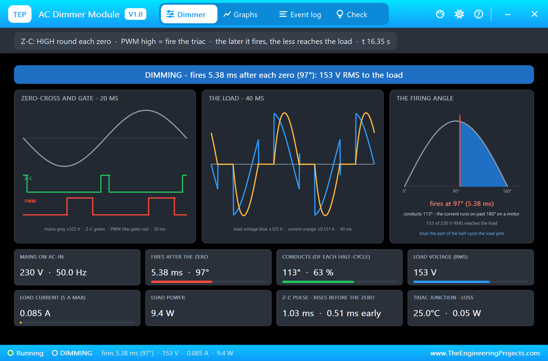
At 12.4 seconds the NTC's pop-up raises the air by 10 degrees, to 32. The bead cannot follow at once: its time constant is 7 seconds. At 13.3 seconds it passes 24 degrees and the program prints "AUTO: 24.2 C - the fan 31 %, fired 6.0 ms after the zero". The dimmer's pop-up shows the firing at 5.38 ms (97 degrees) and 153 V RMS reaching the fan, and the fan starting: 254 r/min and rising.
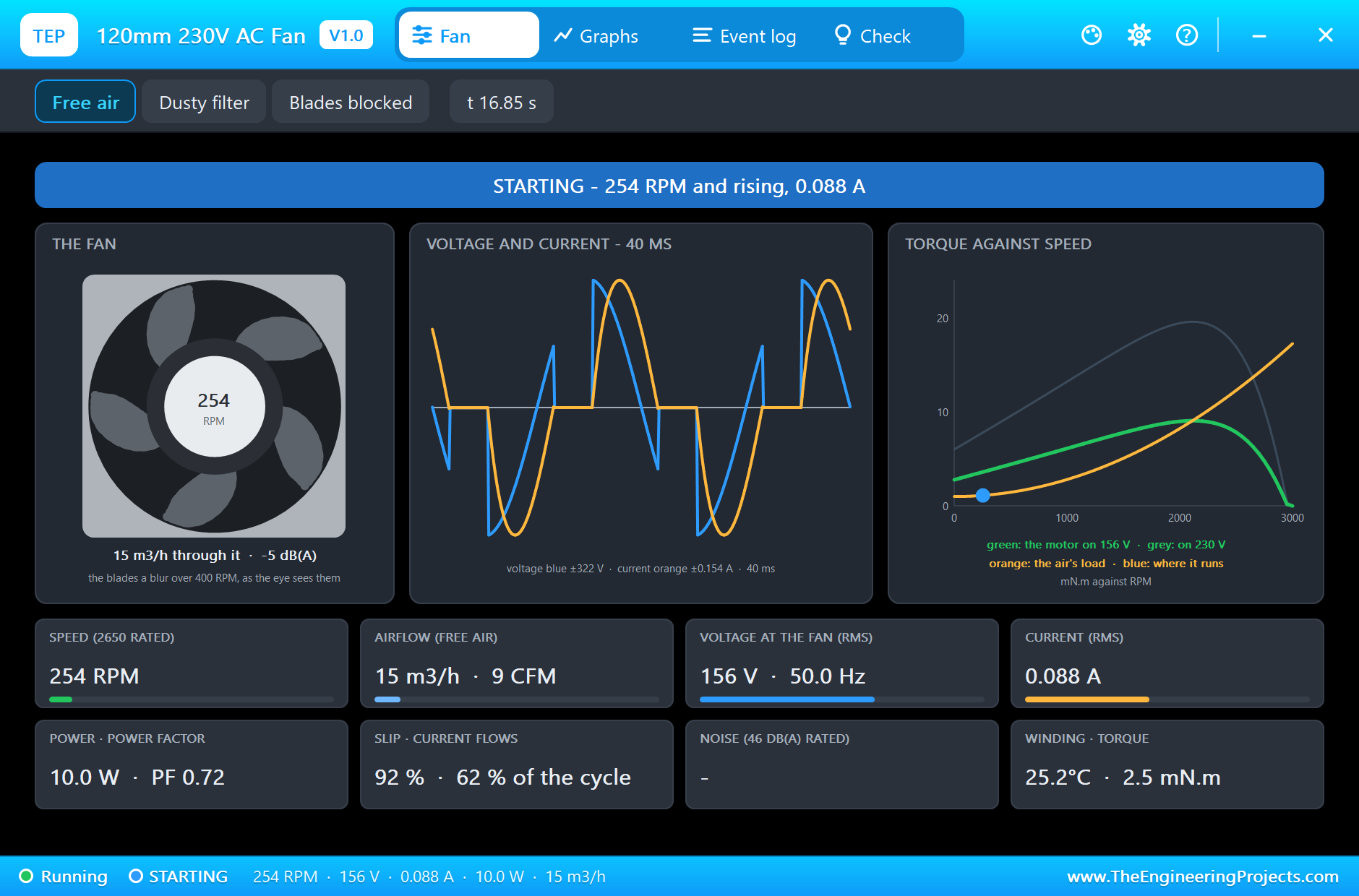
Every half degree of warming adds about 3 % of power: 37 % at 25.2 degrees, 50 % at 27.4, 61 % at 29.3, 71 % at 31.0. The firing moves earlier with it, from 6.0 ms to 3.9 ms. At 26 seconds the dimmer fires at 4.08 ms (73 degrees): 195 V RMS, 0.094 A and 13.2 W, and the fan runs at 2,337 r/min, moving 141 cubic metres of air an hour. On the dimmer's scope, the PWM line now stays high from the firing moment to 8.5 ms after each zero.
Fixed Speeds from the Dashboard
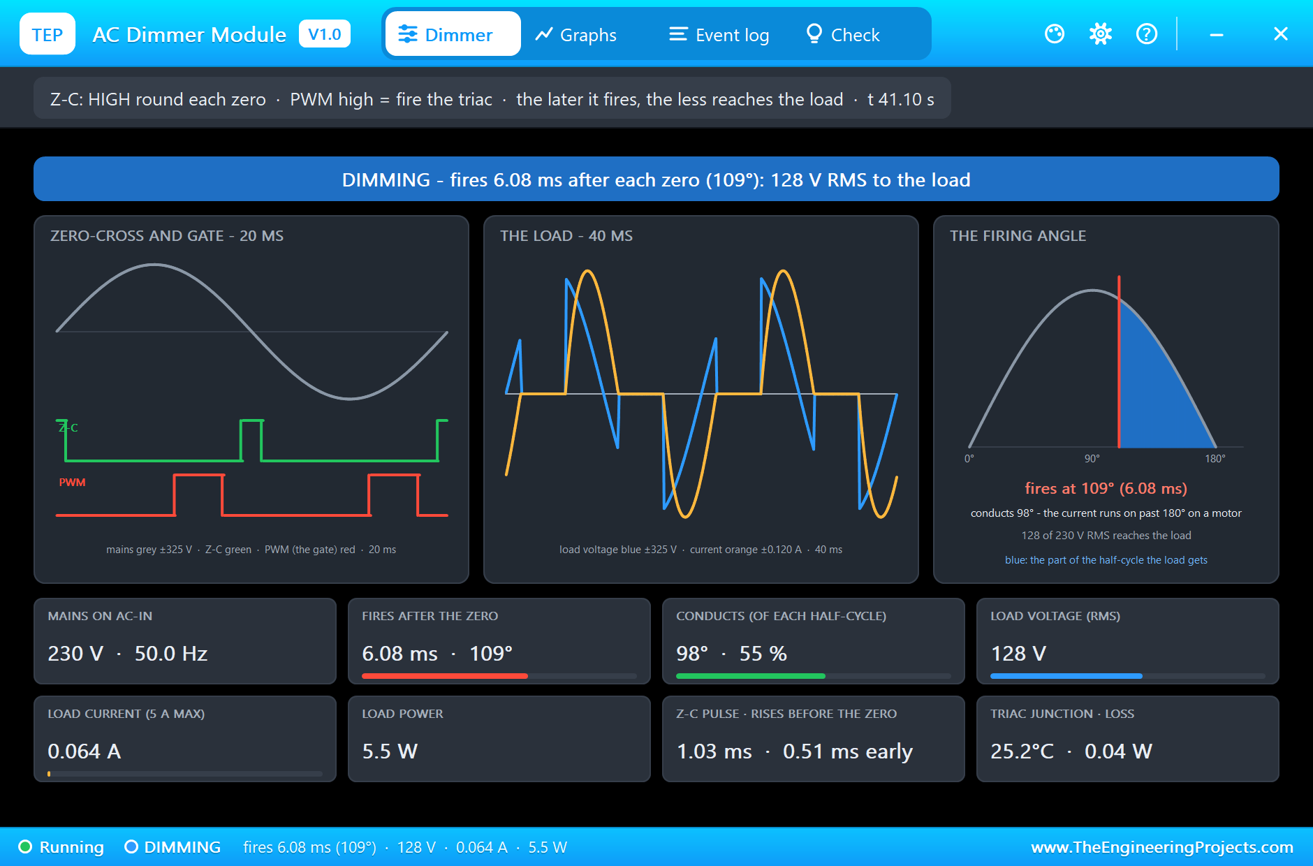
At 28.3 seconds, 100 % on the phone: "fired 0.6 ms after the zero". Now look at the dimmer's pop-up: the triac actually turns on at 2.53 ms (45 degrees), not at 0.6. Until then, the fan's lagging current from the last half cycle is still flowing, and only when it ends can the triac take the new half cycle. Because the gate is still high at that moment, it does: the triac carries the whole cycle, 229 V RMS, 0.115 A and 18.7 W, and the fan reaches 2,639 r/min and 159 cubic metres an hour, its full rated speed. With a 100-microsecond pulse at 0.6 ms, it would have missed every half cycle.
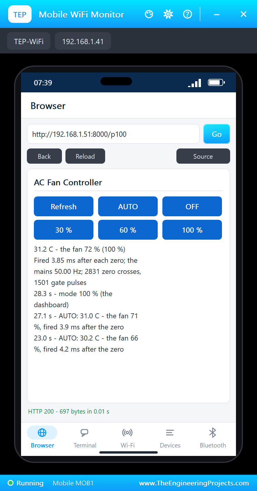
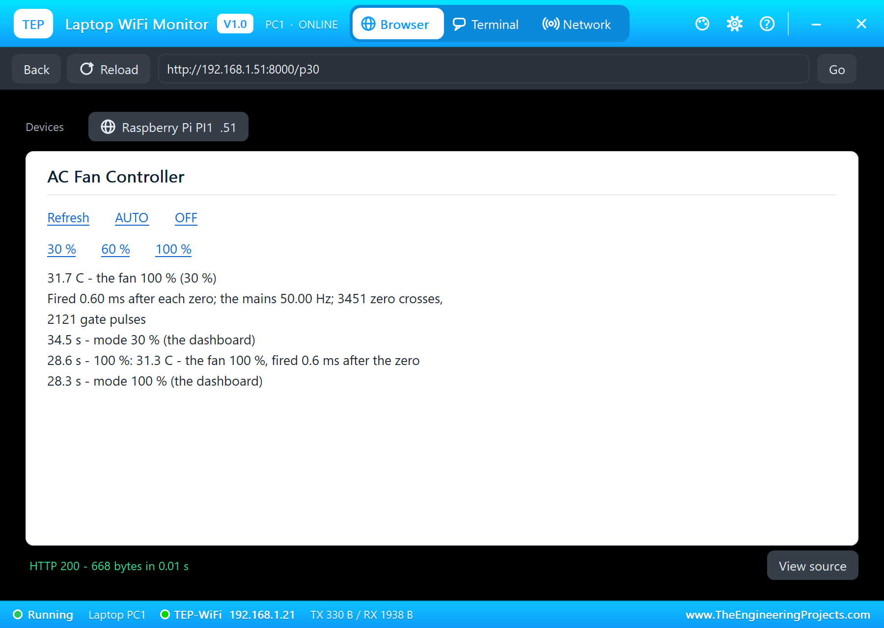
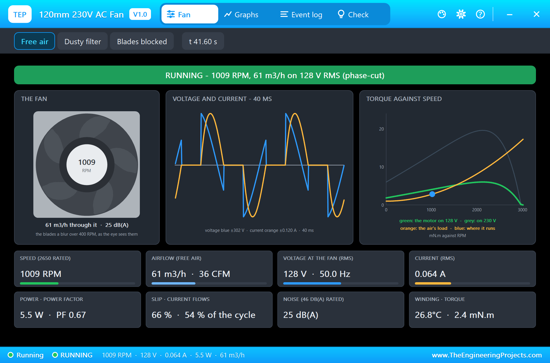
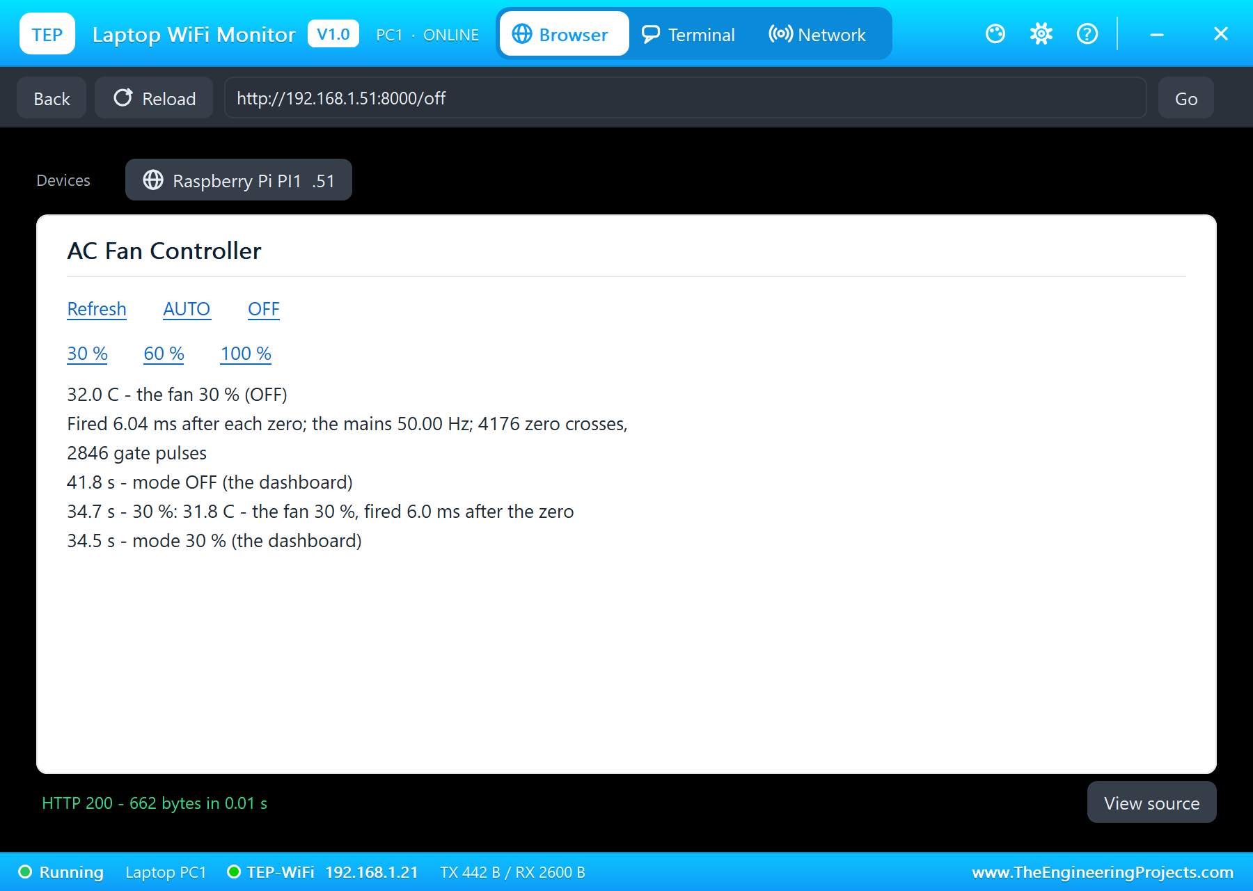
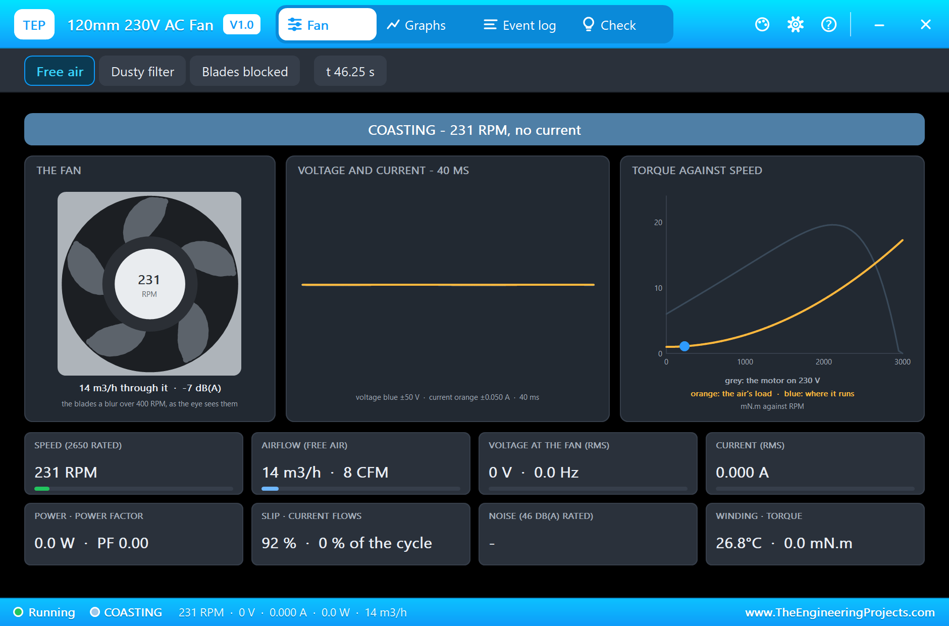
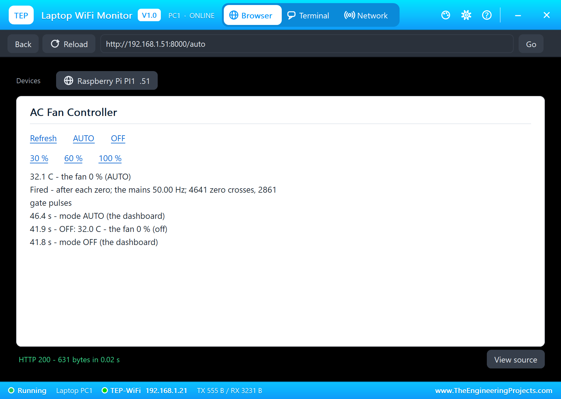
At 34.5 seconds, 30 % on the laptop: the dimmer fires at 6.08 ms (109 degrees), 128 V RMS reaches the fan, 0.064 A and 5.5 W, and it slows to 1,009 r/min and 61 cubic metres an hour. Then OFF at 41.8 seconds: no more firing, and the fan coasts down, still turning at 231 r/min three seconds later. AUTO at 46.4 seconds brings it straight back: 32.1 degrees, 77 %, fired at 3.5 ms.
The Room Cools Down
At 52 seconds the air goes back to 25 degrees, and the bead follows over the next 15 seconds. AUTO turns the fan down step by step: 70 % at 30.9 degrees, 58 % at 28.9, 47 % at 26.9, 42 % at 26.1. At 66 seconds, at 25.9 degrees, the dimmer fires at 5.48 ms (99 degrees): 150 V RMS, 0.076 A and 8.0 W, and the fan turns at 1,483 r/min. The NTC ends at 9.70 kohm, 25.7 degrees.
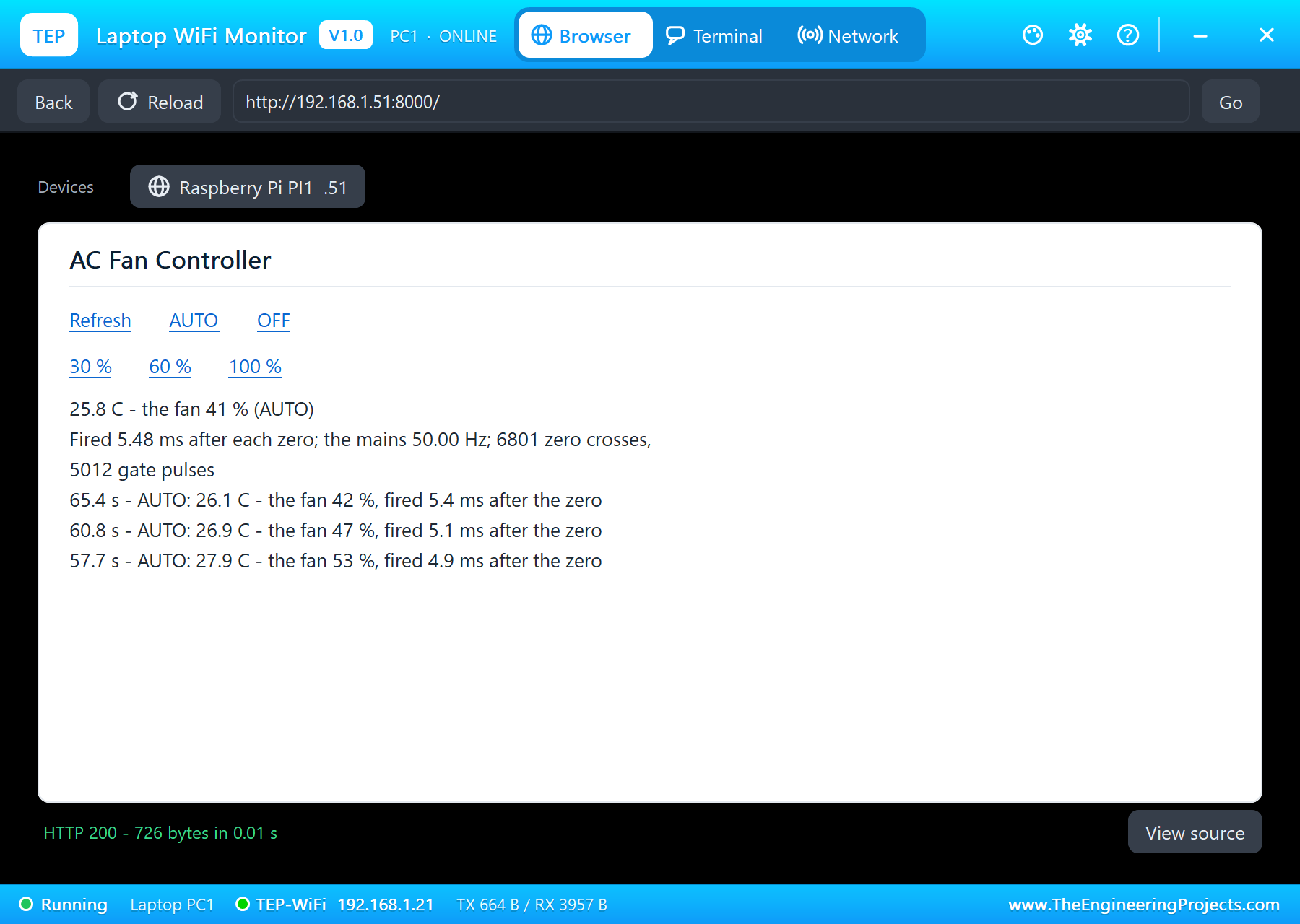
The Numbers of the Run
| Setting | Fired after the zero | Fan voltage | Current, power | Fan speed |
|---|---|---|---|---|
| AUTO, 24.2 C (start) | 5.38 ms (97 deg) | 153 V | 0.085 A, 9.4 W | starting |
| AUTO, about 31 C | 4.08 ms (73 deg) | 195 V | 0.094 A, 13.2 W | 2,337 r/min |
| 100 % | 0.6 ms asked, on at 2.53 ms | 229 V | 0.115 A, 18.7 W | 2,639 r/min |
| 30 % | 6.08 ms (109 deg) | 128 V | 0.064 A, 5.5 W | 1,009 r/min |
| AUTO, 25.9 C | 5.48 ms (99 deg) | 150 V | 0.076 A, 8.0 W | 1,483 r/min |
| OFF | no firing | 0 V | 0 | coasting |
Download the Project Files
Click the button below to download IoT-AC-Fan-Speed-Controller-Raspberry-Pi-5-Proteus-Simulation-v1.0.zip (about 14.3 MB, without the source code of the models):
IoT AC Fan Speed Controller with Raspberry Pi 5 - Proteus Simulation V1.0- Proteus Simulation: Pi-5-AC-Fan-Controller.pdsprj, the program ac_fan.py and copies of the models.
- Python Code: ac_fan.py, the complete program.
- Proteus Library Files: the LIB files of the Raspberry Pi 5, the AC dimmer, the fan, the NTC, the ADS1115, the resistor and the two WiFi Monitors.
- Proteus Model Files: the DLL models and the TEPPi folder, the Python 3.11 and the runtime that the Pi board runs.
- README.txt: the installation steps, the properties, the test results and the links to every library post.
No Proteus yet? Read How to Download and Install Proteus 7 and 8. New to libraries? Follow How to Install a New Library in Proteus.
How to Install the Project Files
- Close Proteus and extract the whole zip file, for example to your Desktop.
- Copy the files from Proteus Library Files into the LIBRARY folder of Proteus.
- Copy everything in Proteus Model Files, the DLL files and the TEPPi folder, into the MODELS folder.
- Start Proteus and open the project from the Proteus Simulation folder.
Changing the Code
The program is plain Python 3: edit ac_fan.py beside the project and press Play again; the Pi board runs the new file. The pins, the AUTO temperatures and the gate timing are at the top. The same program runs on a real Raspberry Pi 5 with Raspberry Pi OS and lgpio; enable I2C in raspi-config. For our other Raspberry Pi 5 project that measures temperature, with a thermocouple, see the IoT Kiln Temperature Monitor with Raspberry Pi 5.
Ideas to Extend the Project
- Add a slider to the dashboard for any power from 0 to 100 %.
- Use a PID loop instead of the straight line, to hold the room at a set temperature.
- Add a soft start: ramp the power up over two seconds, which is kinder to the fan.
- Log the temperature and the power to a file and plot them.
- Add a second NTC outside and run the fan only when the outside air is cooler.
- Control a lamp or a heater with the same circuit: phase control works for any resistive load too.
From Simulation to Real Hardware
- Mains voltage kills: the dimmer's AC-IN and LOAD terminals, the triac's tab and its heatsink carry 230 V. Build it in a closed box, fuse the L line, and never work on it while it is plugged in.
- Keep the logic side apart: never connect anything on the Pi's side to the mains side; the optocouplers are the only bridge.
- Check the fan: shaded-pole and capacitor-run fans can be slowed by phase control; some fans hum at low power, and below about 90 V RMS a fan only hums.
- Linux timing: on a real Pi, the firing thread can be late by a few hundred microseconds when the system is busy; for flicker-free control, use a small microcontroller for the timing or a kernel PWM synchronised to the zero cross.
- Mind the NTC's self-heating: a bigger divider resistor or a lower voltage keeps the bead from warming itself.
Troubleshooting
- The fan never starts: no zero-cross pulses on GPIO17 (the dimmer's VCC), or the mains source is missing.
- The fan runs at full speed whatever the setting: the gate held high across the zero; release it before the next zero.
- The fan stutters at high power: the gate pulse too short for the lagging current; hold it to 8.5 ms.
- The temperature reads a dash: the divider open or shorted, or the ADS1115 not at 0x48.
- The terminal cannot start Python: the TEPPi folder is not in MODELS.
Limitations of the Simulation
- The mains is Proteus's ideal 230 V 50 Hz source; a real mains has noise and small changes of frequency.
- The room's temperature comes from the NTC's pop-up: the fan does not cool the room in the simulation.
- The network is simulated: the dashboard travels between the Pi and the two monitors inside Proteus; the times in this tutorial are simulation time.
- Raspberry Pi is a trademark of Raspberry Pi Ltd; the ADS1115 is made by Texas Instruments. This project is not made or endorsed by them or by Labcenter.
So, that was all about the IoT AC Fan Speed Controller with Raspberry Pi 5 - Proteus Simulation. I hope it helps you control your own mains loads safely: a zero-cross detector for the timing, a triac fired at the right moment and held long enough for a motor, a firing delay worked out from the power you want, and an NTC that lets the fan follow the room, all tested in a simulation before you go near the mains. More IoT projects with the ESP32 and the Raspberry Pi 5 are coming in this series. If you have any questions, ask in the comments and I will help you out. Till the next tutorial, take care and have fun!

Comments
0