


LM358 Dual Op-Amp Library for Proteus


Hello friends, I hope you all are doing great. Today, I am going to share the new LM358 Dual Op-Amp Library for Proteus, the third of the lab ICs in our University Lab series. The LM358 is probably the most used operational amplifier in student labs: two op-amps in an 8-pin package that run from a single supply, with inputs that work down to ground. It amplifies sensor signals, buffers voltages, filters, compares and oscillates, and it is cheap enough to be in every parts box. It also has real limits, and learning them is half of learning analog electronics.
LM358 Dual Op-Amp Library for Proteus
Latest version: V1.0 (November 2026, this tutorial)
Helping Tools
- Serial Monitor Advance: a serial terminal window for the UART of your board
- Serial Monitor Expert: the serial monitor with extra debugging tools
- LCD Library for Proteus V3.0: 16x2, 20x4 and I2C LCDs to show your readings
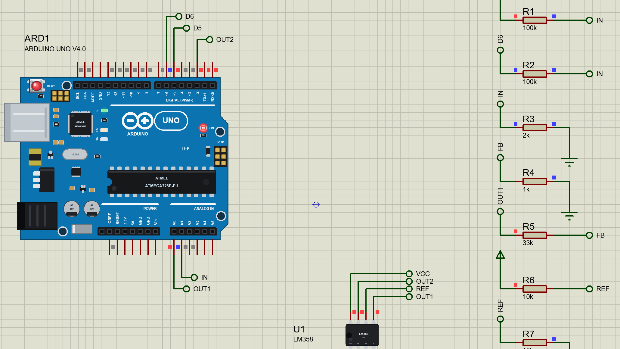
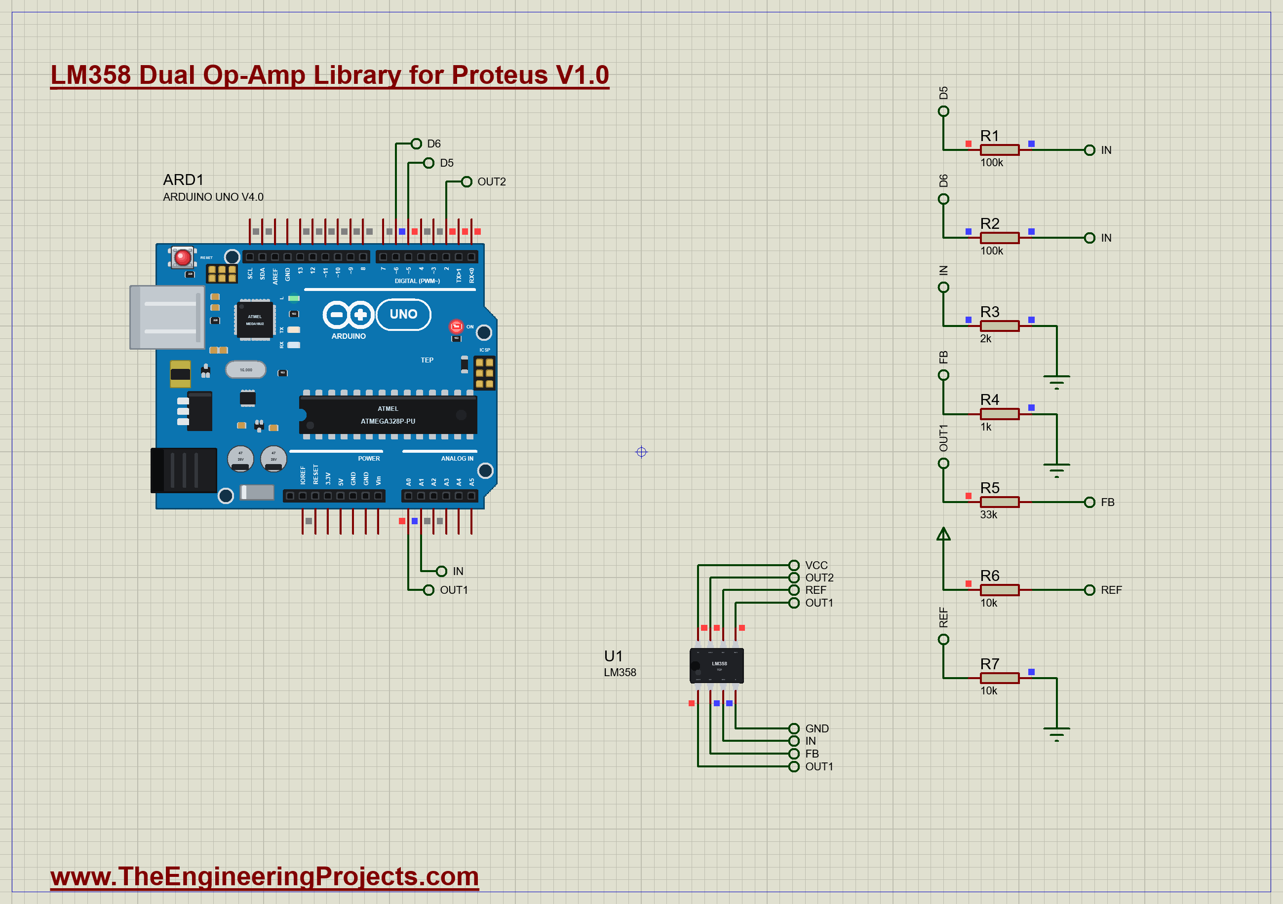
Our library brings the chip itself into Proteus: the PDIP-8 drawn at its true size, 9.81 x 6.35 mm. Each of its two amplifiers follows TI's datasheet for the LM358: the gain-bandwidth of 0.7 MHz, the slew rate of 0.3 V/us, the open-loop gain, the input offset and bias current, and, above all, the output that stops 1.5 V below the supply. The pop-up shows both amplifiers live and catches every fast edge on a microsecond scope. The demo is an Arduino that drives a gain-34 amplifier, watches it saturate, and times an op-amp used as a comparator.
NOTICE: Our team has put a lot of effort into these small parts: the bodies, the animation and the pop-ups are all our own design, and you get them free. Your feedback is the fuel that keeps us going, so please tell us what you think in the comments below or in the LM358 board of our forum. And if our free libraries help you, you can buy us a coffee. So, let's get started with the LM358 Dual Op-Amp Library for Proteus:
What is the LM358?
An operational amplifier is a very high gain differential amplifier: it multiplies the difference between its two inputs, IN+ and IN-, by a huge number and puts the result on its output. On its own that gain is useless, because the output hits a rail at the slightest difference. With negative feedback, a part of the output brought back to IN-, the op-amp drives its output to whatever value makes the two inputs equal, and the gain of the whole circuit is set by a couple of resistors. The LM358 holds two such amplifiers, sharing one supply.
| LM358 (VS = 5 V, 25 °C) | |
|---|---|
| Supply | 3 V to 30 V single supply, 350 uA per amplifier |
| Gain-bandwidth | 0.7 MHz |
| Slew rate | 0.3 V/us |
| Open-loop gain | 100 V/mV (25 V/mV minimum) |
| Input offset | 3 mV typical, 7 mV maximum |
| Input bias | -20 nA typical (out of the input) |
| Input range | from V- to V+ - 1.5 V |
| Output swing | from V- + 5 mV to V+ - 1.5 V (RL 2 kΩ or more) |
| Output current | 30 mA source, 20 mA sink typical; 40 mA short-circuit |
The Pins
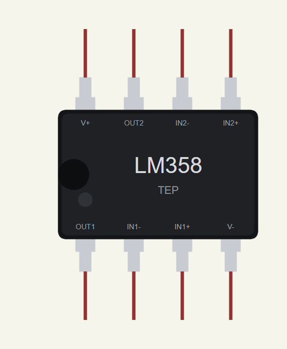
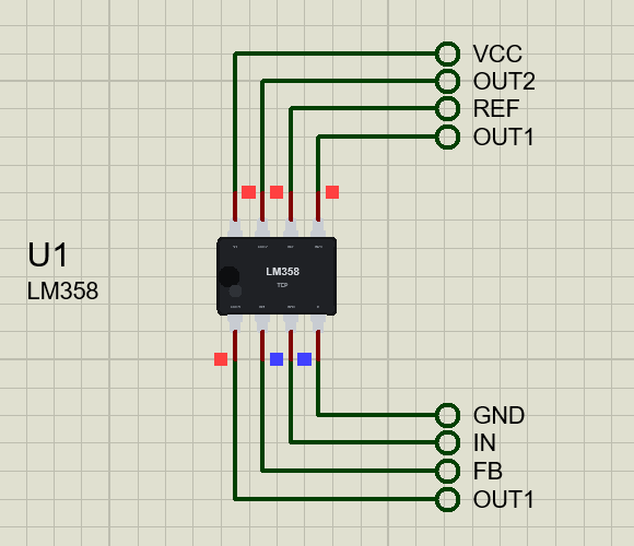
Pin 1 is OUT1, 2 is IN1-, 3 is IN1+, 4 is V- (ground in single-supply use), 5 is IN2+, 6 IN2-, 7 OUT2 and 8 V+. Our drawing lies on its side with the notch on the left: amplifier 1 and V- along the bottom, V+ and amplifier 2 along the top.
The Limits That Matter
The output swing. The LM358's output can go right down to about 5 mV above ground, which is why it is popular for single-supply circuits. But at the top it stops about 1.5 V below V+. On a 5 V supply that is 3.5 V, and no amount of gain can push it further. The inputs share the same limit: they work from ground up to V+ - 1.5 V.
Gain-bandwidth. The open-loop gain falls with frequency so that gain times bandwidth stays about 0.7 MHz. A circuit with a gain of 10 has about 70 kHz of bandwidth, a gain of 100 about 7 kHz. Our demo's gain of 34 leaves about 20 kHz.
Slew rate. However large the signal, the output cannot move faster than 0.3 V per microsecond. A 3 V step takes at least 10 us, and a full-swing sine wave above a few kilohertz turns into a triangle.
Offset and bias. A real op-amp behaves as if a small voltage, the offset, sat in series with its input: typically 3 mV for the LM358. The circuit multiplies it like any other input, so a gain of 34 turns 2 mV of offset into 68 mV at the output with no input at all. The inputs also draw a small bias current, about 20 nA, which matters only with high-value resistors.
Features of the LM358 Dual Op-Amp Library for Proteus
- The real chip at true scale: the PDIP-8, 9.81 x 6.35 mm, with its real pinout.
- Two amplifiers from the datasheet: 0.7 MHz gain-bandwidth, 0.3 V/us slew rate, 100 V/mV open-loop gain.
- The real output swing: from 5 mV above V- to 1.5 V below V+.
- Offset and bias: a settable offset per amplifier (VOS) and the -20 nA input bias current.
- Warnings: inputs above V+ - 1.5 V and output currents over 40 mA are reported.
- A microsecond scope: the pop-up catches amplifier 1's last fast edge with its 10 - 90 % time and its steepest slope.
- A pop-up: both amplifiers live with their state, eight values, graphs, an event log and a check page.
- A complete package: about 1.2 MB with the library, our Arduino UNO V4.0 and the demo, without the source code of the model.
The LM358 in Proteus
The device is LM358TEP in TEPLM358.LIB, under Lab ICs, with the prefix U and the analog model TEPLM358.DLL. Search LM358 in Pick Devices. Its one property, VOS, sets the input offset of the two amplifiers in millivolts; the default "2, -1" is within the datasheet's typical 3 mV.
Download LM358 Dual Op-Amp Library for Proteus
Click the button below to download LM358-Dual-Op-Amp-Library-for-Proteus-v1.0.zip (about 1.2 MB, without the source code of the models):
LM358 Library for Proteus V1.0- README.txt: installation, the demo, the wiring, troubleshooting and the limits.
- Proteus Library Files:
TEPLM358.LIBand ourArduinoV4TEP.LIB. - Proteus Model Files:
TEPLM358.DLLandTEPARDUINO.DLL. - Arduino Code: the demo sketch.
- Proteus Simulation: the demo project, its HEX file and copies of the DLLs.
No Proteus yet? Read How to Download and Install Proteus 7 and 8. New to libraries? Follow How to Install a New Library in Proteus.
How to Install LM358 Dual Op-Amp Library for Proteus
- Close Proteus and extract the whole zip file, for example to your Desktop.
- Copy the files from Proteus Library Files into the LIBRARY folder of Proteus.
- Copy the files from Proteus Model Files into the MODELS folder.
- Delete
TEPLM358.IDXfrom the LIBRARY folder if it is there. - Start Proteus, press P and search for LM358.
Demo: An Amplifier and a Comparator
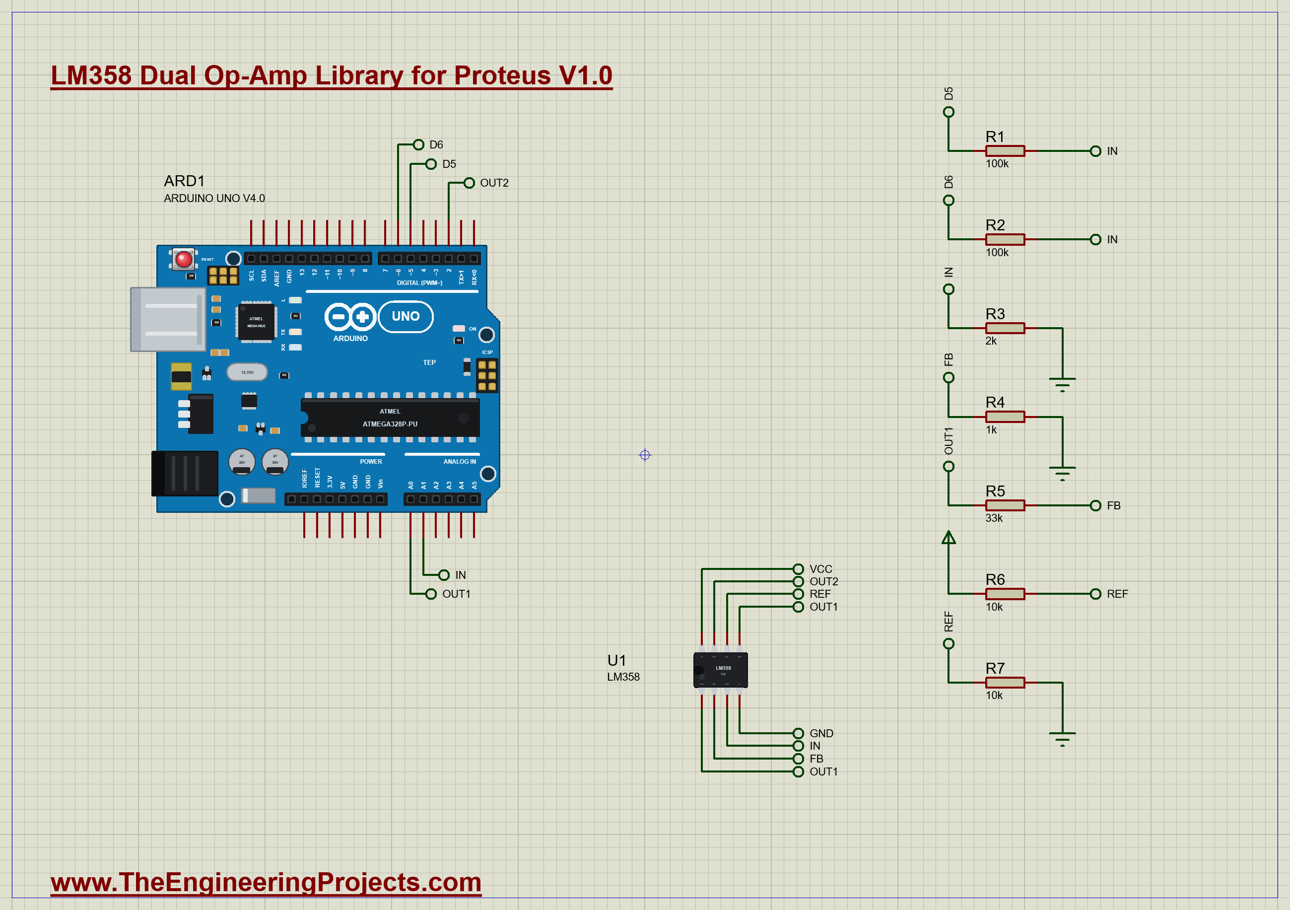
The demo has our Arduino UNO Library for Proteus V4.0 with its built-in monitor, the same window as our TEP Serial Monitor Advance for Proteus, the LM358 on 5 V, and seven resistors. Amplifier 1 is a non-inverting amplifier: its IN+ is the node IN, and 33 kΩ from OUT1 to IN- with 1 kΩ from IN- to ground set the gain to 1 + 33 / 1 = 34. The input comes from the UNO's D5 and D6, each through 100 kΩ, with 2 kΩ to ground, so every pin that is high adds about 96 mV. Amplifier 2 is used as a comparator: OUT1 on its IN+, 2.5 V from two 10 kΩ resistors on its IN-, and its output to the UNO's D2. A0 measures OUT1 and A1 measures IN. Open LM358-OpAmp-ArduinoUnoV4.pdsprj.
The Sketch
IN is only about 96 mV, less than 20 steps of the UNO's converter on its usual 5 V range. So the sketch reads it against the UNO's internal 1.1 V reference, about 1.07 mV a step, and switches back to the 5 V range for OUT1:
float readIn() {                                                               // A1 against 1.1 V: about 1.07 mV a step
  analogReference(INTERNAL); analogRead(A1); delay(5);
  long sum = 0; for (int i = 0; i < 16; i++) sum += analogRead(A1);
  analogReference(DEFAULT); analogRead(A0); delay(5);
  return sum / 16.0 * 1.1 / 1024;
}
It prints IN, OUT1, their ratio and the comparator's output for three inputs: both pins low, D5 high, and both high. Then it times how long the comparator takes to follow a step, rising and falling, five times each:
unsigned long t0 = micros(); digitalWrite(DRIVE1, HIGH); while (digitalRead(COMP) == LOW) {} up += micros() - t0;After that D5 flips every 100 ms, a square wave for the pop-up's scope.
Run the Demo
Open the project and press Run. The demo runs 6 simulated seconds, which Proteus ran in about two minutes on our PC. Click the chip to open its pop-up; everything below is from that one run, the demo exactly as it ships.
No Input: the Offset
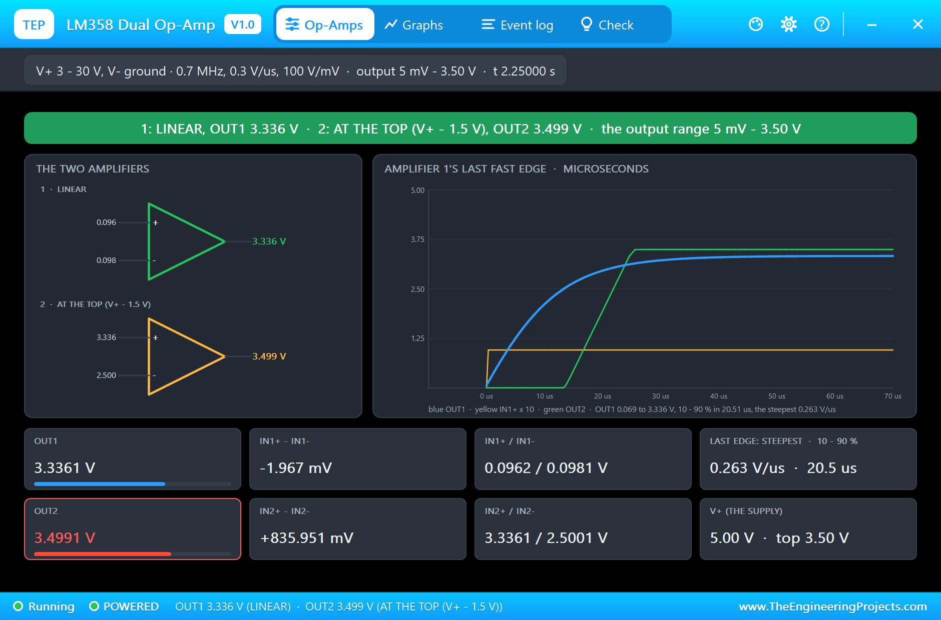
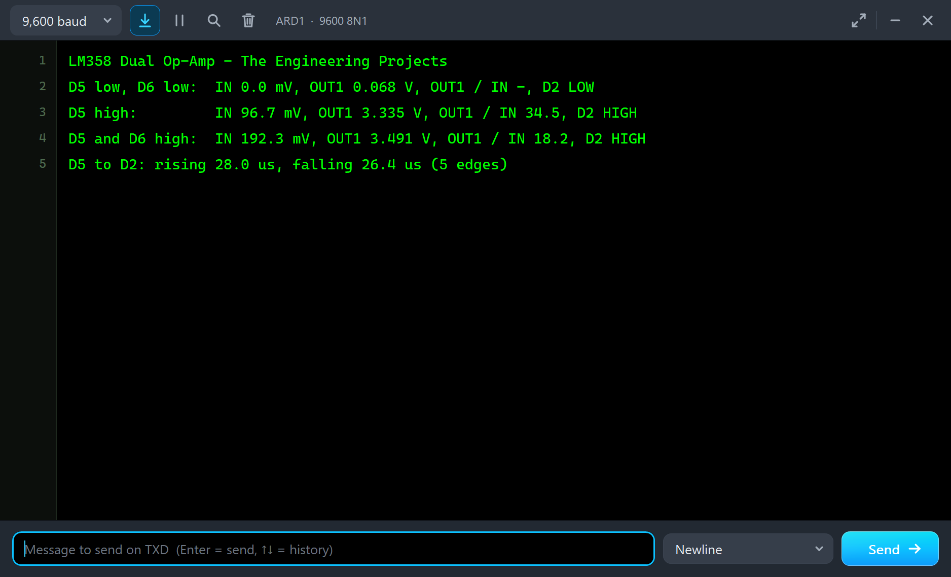
With both pins low, IN is 0 V, yet OUT1 sits at 0.068 V. That is the offset at work: amplifier 1's 2 mV offset times the gain of 34 gives 68 mV. Amplifier 2 sees 68 mV against 2.5 V, so the comparator's output is low, about 6 mV, and D2 reads LOW.
D5 High: the Gain
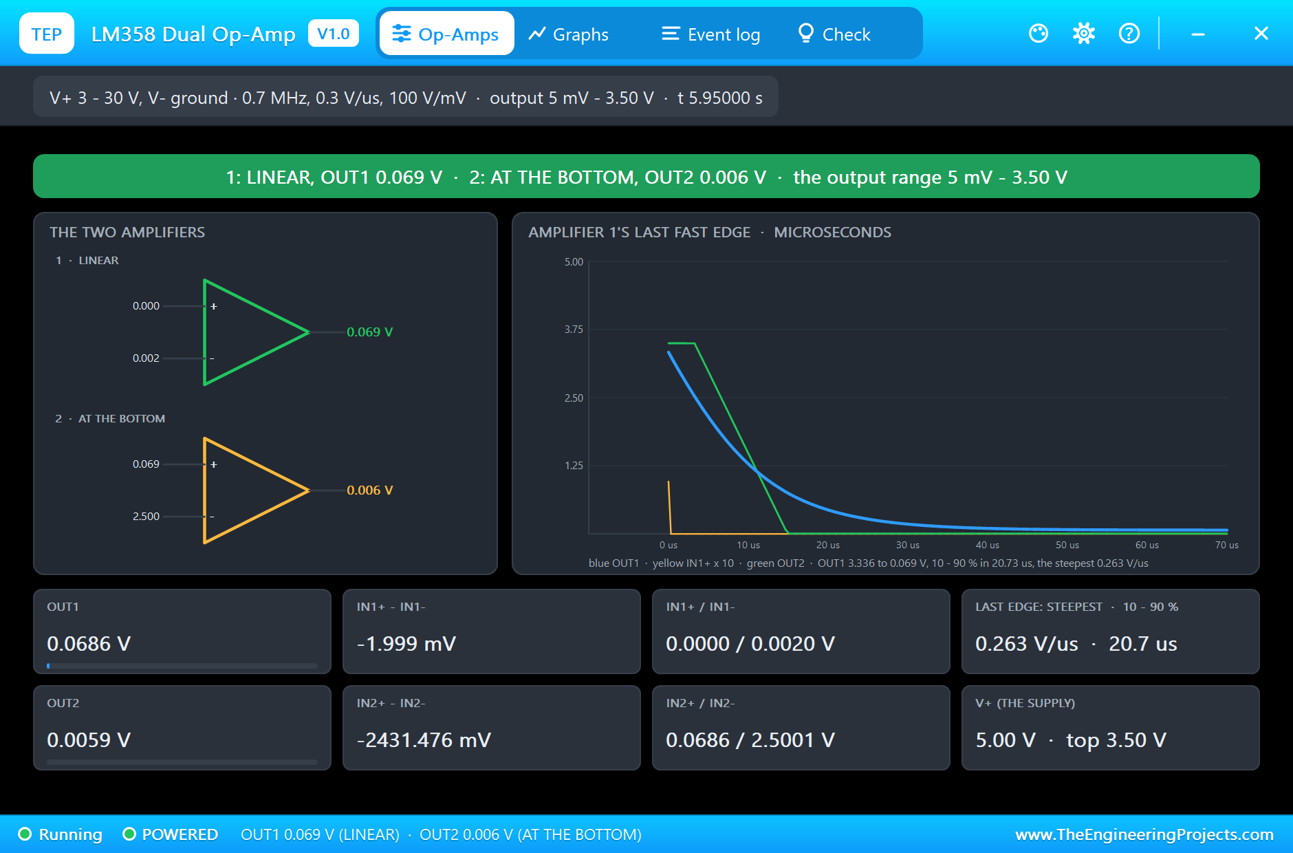
With D5 high, the model shows IN at 96.17 mV and OUT1 at 3.3361 V. Look at the inputs: IN1+ is 96.2 mV and IN1- is 98.1 mV, 1.97 mV apart. That is what negative feedback does: the op-amp moves its output until its inputs differ only by the offset. The sketch measures IN as 96.7 mV and OUT1 as 3.335 V, a ratio of 34.5; the expected 34 is slightly raised by the offset, and the UNO's reading of IN is within one step. OUT1 is now above 2.5 V, so the comparator's output goes to the top of its range, 3.499 V, and D2 reads HIGH. That 3.5 V is the LM358's limit on a 5 V supply, and it is still high enough for the UNO, which needs 3 V for a HIGH.
Both High: the Output Limit
With both pins high, IN doubles to 192.3 mV, and the circuit asks for 34 x 0.192 = 6.5 V. The LM358 cannot give it: OUT1 stops at 3.494 V, and the sketch reads 3.491 V, a ratio of only 18.2. The feedback loop is broken now, the inputs are far apart, and the amplifier simply sits at its ceiling, 1.5 V below its supply. This is the most common surprise with the LM358 on 5 V, and the reason rail-to-rail op-amps exist.
Edges in Microseconds
When D5 goes high, IN jumps by 96 mV at once, but OUT1 needs time. The pop-up's scope shows it: OUT1 rises from 0.069 to 3.336 V, 10 to 90 % in 20.5 us, with a steepest slope of 0.263 V/us. Two limits share that edge. At first the input difference is large and the output rises at nearly the full slew rate; a 96 mV step does not quite drive the LM358's input stage to its 0.3 V/us. As OUT1 closes in, the difference shrinks and the gain-bandwidth takes over: with a gain of 34 the bandwidth is about 20 kHz, a time constant of about 8 us, and the last part of the rise is a slow exponential.
The comparator's output, the green line, waits until OUT1 crosses 2.5 V and then runs up at the full slew rate, because its input difference is large. An op-amp used as a comparator works, but it is slow: the sketch measured 28.0 us from D5 to D2 rising and 26.4 us falling, including its own loop time. A real comparator such as the LM393 switches in about a microsecond.
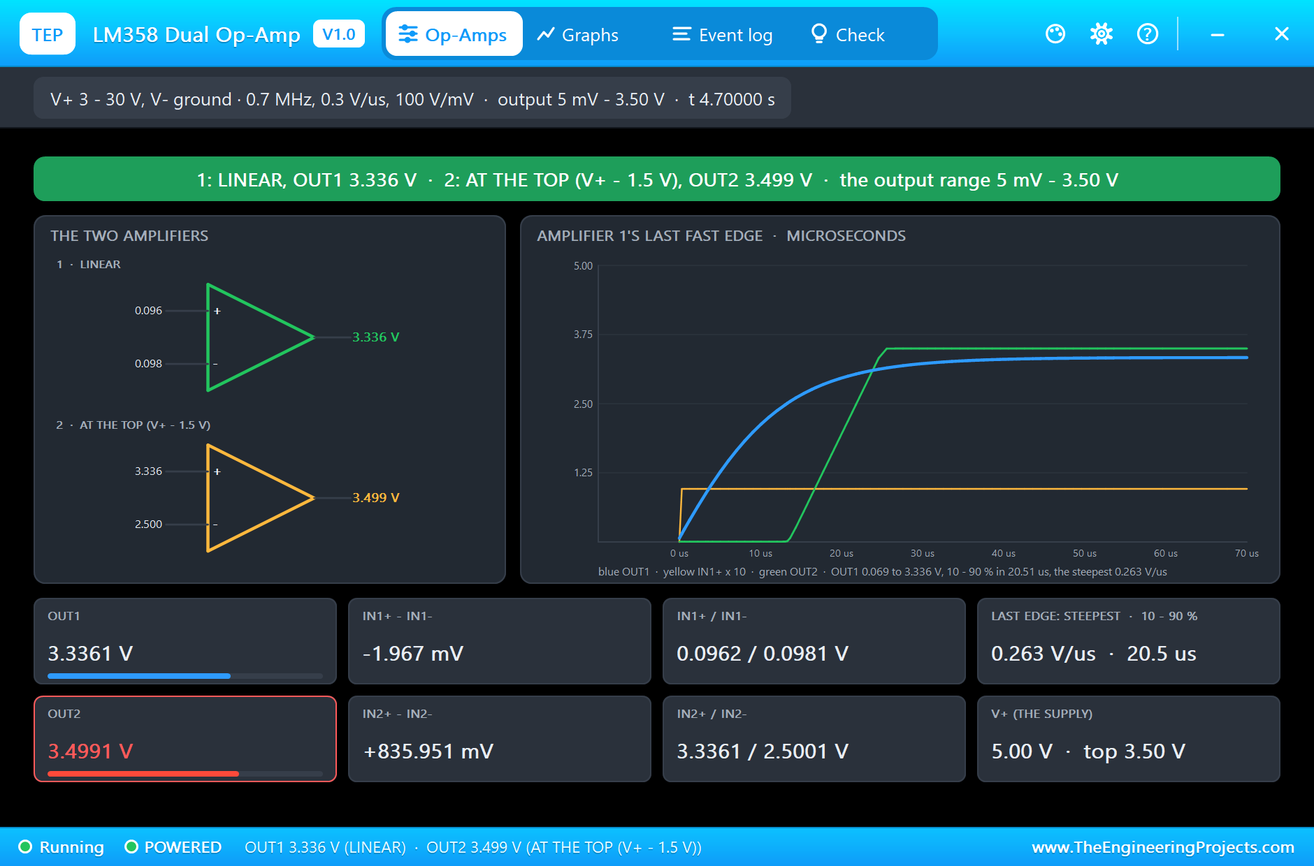
The falling edge mirrors it: OUT1 from 3.336 down to 0.069 V in 20.7 us, the comparator dropping to 6 mV.
The Graphs, the Log and the Check Page
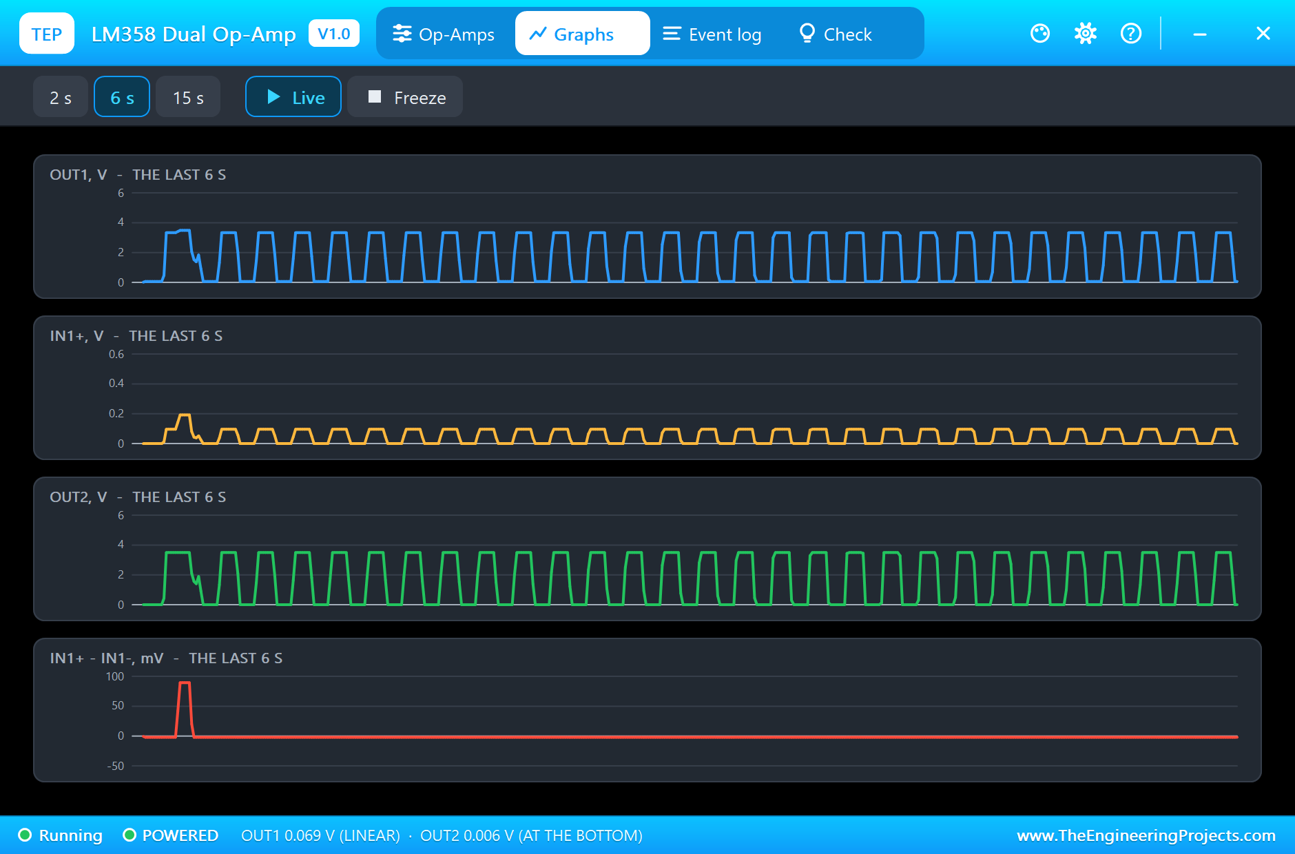
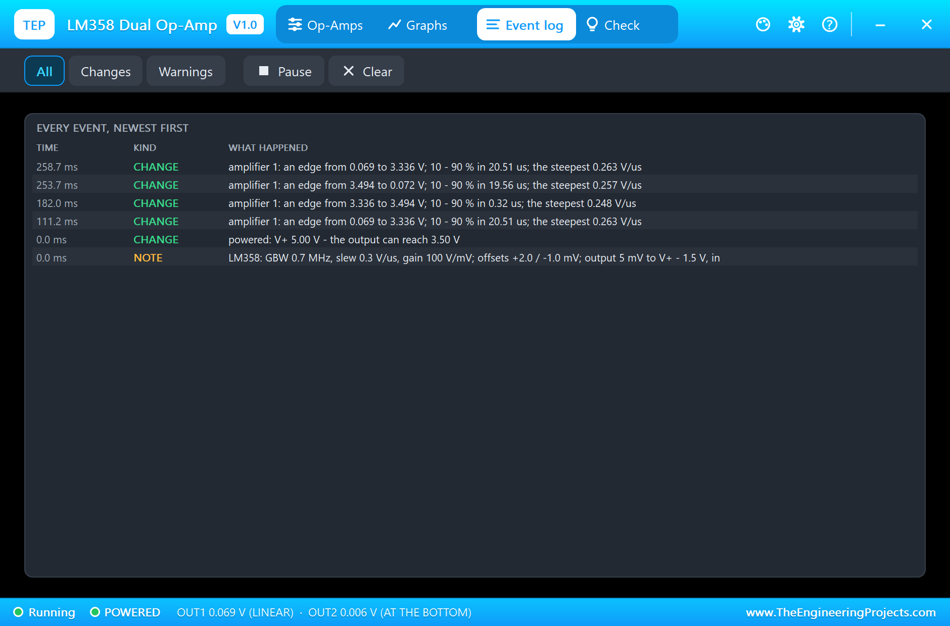
The Graphs page plots OUT1, IN1+, OUT2 and amplifier 1's input difference over the last 2, 6 or 15 simulated seconds. The Event log records the power-up and the first edges with their timing, including the small step from 3.336 to 3.494 V when D6 pushed OUT1 into its limit.
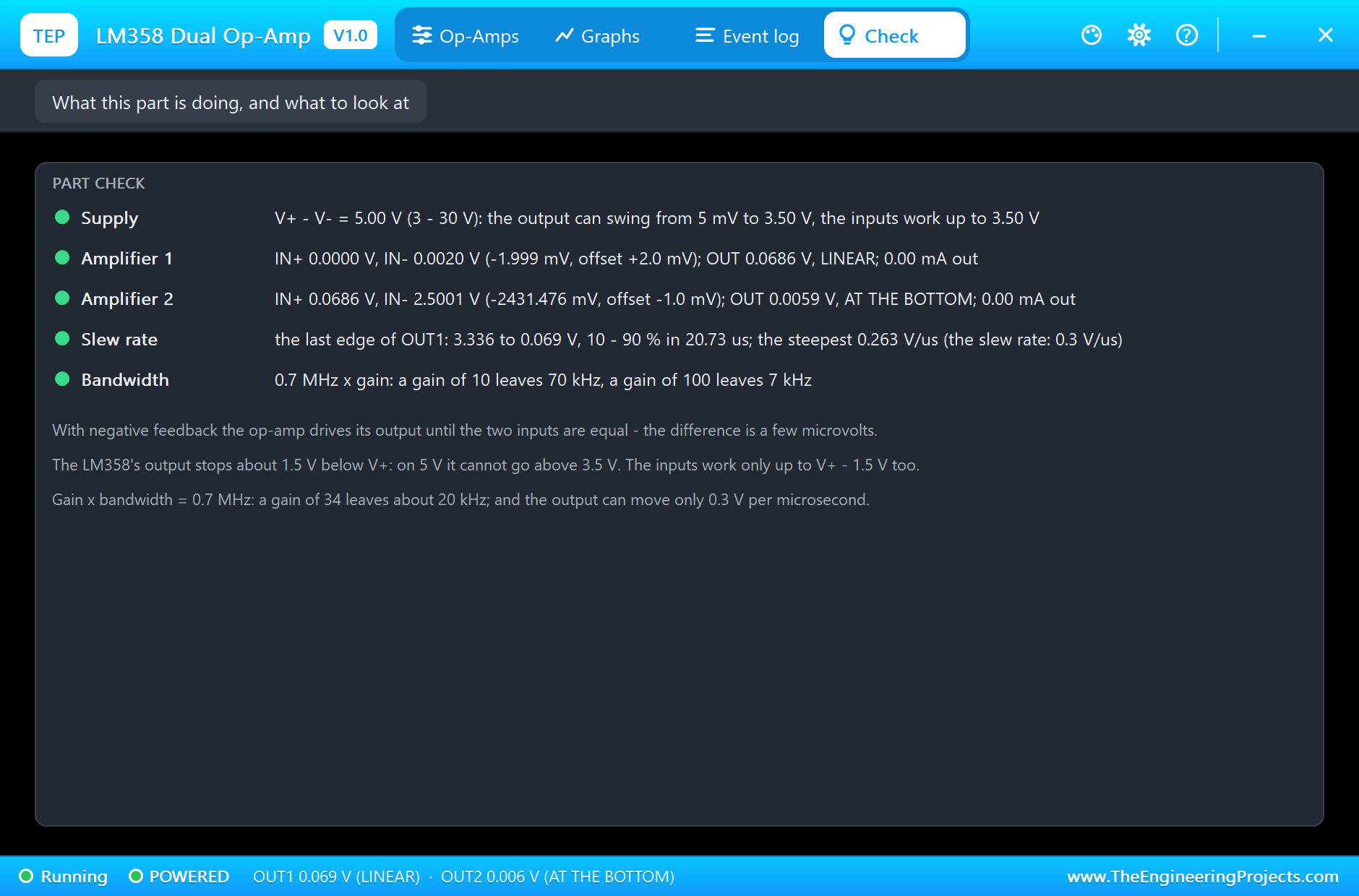
The Check page sums up the chip: the supply and the output and input ranges it allows, both amplifiers with their inputs, offset, output, state and current, the last edge, and the bandwidth left at a few gains.
Try It Yourself
- Change R5 to 10 kΩ for a gain of 11 and see the output stay out of saturation with both pins high.
- Set VOS to "0, 0" and see OUT1 fall to 0 V with no input.
- Make amplifier 2 a voltage follower (OUT2 to IN2-) and watch it slew a full step at 0.3 V/us.
- Give the comparator hysteresis with a resistor from OUT2 to IN2+.
- Raise the gain to 100 and measure the slower edge: 0.7 MHz / 100 leaves 7 kHz.
- Run the LM358 from 12 V and see the output reach 10.5 V.
Ideas to Extend the Demo
- Amplify a thermocouple or a strain gauge and read it with the UNO.
- Build a two-stage active filter with the two amplifiers.
- Make a square-wave oscillator from amplifier 2, a capacitor and three resistors.
- Buffer the MCP4725 DAC from our earlier library to drive a heavier load.
Your Own Sketches
The demo sketch is in the zip file, and you can change it in the Arduino IDE. New to Arduino? Start with our Arduino Tutorial for Beginners. Export the compiled binary, and set the UNO's PROGRAM property to the new file. Our guide on How to get the HEX file from Arduino shows you where the file ends up.
Things to Know Before Using a Real Chip
- The output stops 1.5 V below V+: on 5 V it reaches only about 3.5 V; choose a rail-to-rail op-amp for a full swing.
- Mind the input range: both inputs from ground to V+ - 1.5 V; that is perfect for sensors near ground.
- The offset is multiplied: up to 7 mV times the gain; trim it or use AC coupling at high gains.
- Slow as a comparator: microseconds; use a real comparator for fast edges.
Troubleshooting
- NO SUPPLY: V+ is missing or under 3 V.
- The output stops at about 3.5 V on 5 V: that is the LM358's output swing.
- The output is not 0 with no input: the offset times the gain.
- The output is slow: 0.3 V/us slew rate, and 0.7 MHz divided by the gain.
- An input-range warning: an input went above V+ - 1.5 V.
- The part is not simulated:
TEPLM358.DLLis missing from MODELS and from the project folder.
Limitations of the Simulation
- The output current limit is not modelled; currents over 40 mA are reported on the Check page.
- The weak sink near ground (30 uA at 200 mV) and the crossover distortion are not modelled.
- Noise, the common-mode and supply rejection and temperature drift are not modelled.
- Arduino is a name of Arduino and LM358 is an industry part number; this library is not made or endorsed by Arduino, Labcenter or Texas Instruments.
- Tested in Proteus 8.5 in November 2026 (the demo as shipped). Proteus 7 is not supported.
So, that was all about the LM358 Dual Op-Amp Library for Proteus. I hope it helps you build your analog circuits on your own PC first: real gain, real limits, and a microsecond scope that shows why. If you have any questions, ask in the comments and I will help you out. Till the next tutorial, take care and have fun!

Comments
0