


DHT11 / DHT22 Library for Proteus V1.0: Temperature Humidity Sensor


Hello friends, I hope you all are doing great. Today, I am going to share the new DHT11 / DHT22 Library for Proteus V1.0. The DHT11 and the DHT22 are the temperature and humidity sensors of almost every first weather station, greenhouse, incubator and smart home project. They are cheap, they need only one data wire, and the Adafruit library reads them in two lines of code. Now you can build and test them in Proteus, on the small 3-pin modules most of us buy.
Behind the parts sits our own model, not a part that shows a number. It speaks the sensors' real single-wire protocol: it waits for the Arduino's start signal, measures how long DATA was held LOW, answers with LOW and HIGH pulses and sends 40 bits, each timed like the datasheet's, with the checksum. It also behaves like the real sensors where they surprise people: it sends its last measurement, it does not answer when asked too often, and a DHT11 cannot measure below 0 C. You get four devices: the DHT11 module and the DHT22 (AM2302) module, each as a Simple device with a live STATUS panel and air controls, and as an Advance device with a pop-up window and three test tools. The demo runs the Adafruit DHT sensor library on our Arduino UNO V4.0.
NOTICE: a DHT library is easy to fake: read the number from a property and hand it to the Arduino. We wanted more. Our sensors answer the real start signal with the real pulses, so the Adafruit library reads them exactly as on your desk, and the classic mistakes fail exactly as they do there. It took our team a lot of hard work. Your feedback is the fuel that keeps us going, so please tell us what you think in the comments below or in the DHT11 / DHT22 board of our forum. And if our free libraries help you, you can buy us a coffee. So, let's get started with the DHT11 / DHT22 Library for Proteus V1.0:
What are the DHT11 and the DHT22?
Both are made by Aosong. Inside the plastic case sits a small humidity sensing element, a thermistor and an 8-bit controller that measures both and sends the result over one data wire. The DHT11 is the cheap blue one: whole degrees and whole percent, 0 to 50 C, 20 to 90 %RH. The DHT22, also sold as the AM2302, is the bigger white one: tenths of a degree and of a percent, -40 to 80 C and 0 to 100 %RH, and more accurate. For the sensors themselves, read our Introduction to DHT11 and Introduction to DHT22; for a first sketch on real hardware, our DHT11 Arduino Interfacing.
| DHT11 | DHT22 / AM2302 | |
|---|---|---|
| Temperature | 0 to 50 C, +-2 C, 1 C steps | -40 to 80 C, +-0.5 C, 0.1 C steps |
| Humidity | 20 to 90 %RH, +-5 %, 1 % steps | 0 to 100 %RH, +-2 %, 0.1 % steps |
| Readings | one a second | one every 2 seconds |
| Start signal | DATA LOW for at least 18 ms | DATA LOW for at least 0.8 ms (typically 1 ms) |
| Supply | 3.3 to 5.5 V | 3.3 to 6 V |
| The module | 3 pins: VCC, DATA, GND; a 10 kohm pull-up on DATA, a red power LED | the same |
| Devices | DHT11TEP (Simple), DHT11ADVTEP (Advance) | DHT22TEP (Simple), DHT22ADVTEP (Advance) |
How the Single-Wire Bus Works
The bus has one wire and a pull-up resistor, so it rests HIGH. To read the sensor, the Arduino pulls DATA LOW for a while, the start signal, and then lets it go. The sensor answers a few tens of microseconds later: it pulls DATA LOW for about 80 us, lets it go for about 80 us, and then sends 40 bits. Every bit starts with a LOW of about 50 us; the HIGH that follows is short, about 26 us, for a 0, and long, about 70 us, for a 1. A last LOW of 50 us ends the answer, and the pull-up holds DATA HIGH again. The whole answer takes about 4 ms.
The 40 bits are five bytes: two for the humidity, two for the temperature and a checksum, the low byte of the sum of the other four. The DHT22 sends tenths: 513 means 51.3 %, and the top bit of the temperature means minus. The DHT11 sends whole numbers, so its second and fourth bytes are 0. The Adafruit library times every pulse with the interrupts off, decides each bit by comparing its HIGH with its LOW, and checks the checksum.
The Last Measurement
Here is the detail that surprises people most. The sensor does not measure when you ask. It sends the result of its previous measurement and then measures again, ready for the next reading. So when the air changes, the first reading after the change still shows the old values, and the second one shows the new ones. While the sensor measures it does not answer at all, which is why a DHT22 wants 2 seconds between readings and a DHT11 one second.
What's New in DHT11 / DHT22 Library for Proteus V1.0
- Two real modules: the light blue DHT11 on a blue PCB and the white DHT22 on a black PCB, each with its 3-pin header, the 10 kohm pull-up, a 100 nF capacitor and the red power LED.
- Two styles: each module as a Simple device with a STATUS panel and as an Advance device with a pop-up window.
- The real protocol: the start signal measured, the answer and the 40 bits driven with the datasheets' times, the checksum, the DHT11 and DHT22 encodings with the minus bit.
- The real behaviour: the last measurement, 1 s to settle after power-up, no answer while measuring, the ranges of both sensors.
- Air controls: set the temperature and the humidity with - / + buttons and six presets, on the panel or in the pop-up, while the simulation runs.
- Mistake detection: the wrong type in the sketch, readings too often, too early, the air outside the range, the pin left as an OUTPUT, VDD too low, no power.
- Three test tools on the Advance devices: Start signal, Readings and Range.
- A two-node demo on our Arduino UNO V4.0 with the Adafruit DHT sensor library: both sensors side by side on each node, Simple on node 1 and Advance on node 2.
- A compact package: about 1.26 MB, without the C++ source code of the model.
Four Devices: Two Modules, Simple and Advance
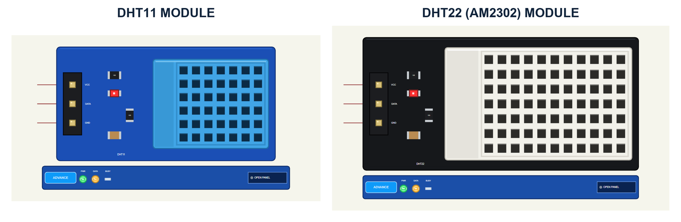
The modules look like the ones on your desk. The sensor lies face up with its grille of openings, its legs toward the header. The DHT11 is 15.5 by 12 mm, the DHT22 25 by 15.1 mm, both drawn at twice their real size so the details stay readable on a schematic. Next to the header sit the 10 kohm pull-up (103), the power LED with its resistor (102) and the 100 nF capacitor. The pins are VCC, DATA and GND, on the left, ready for the wires to the Arduino.
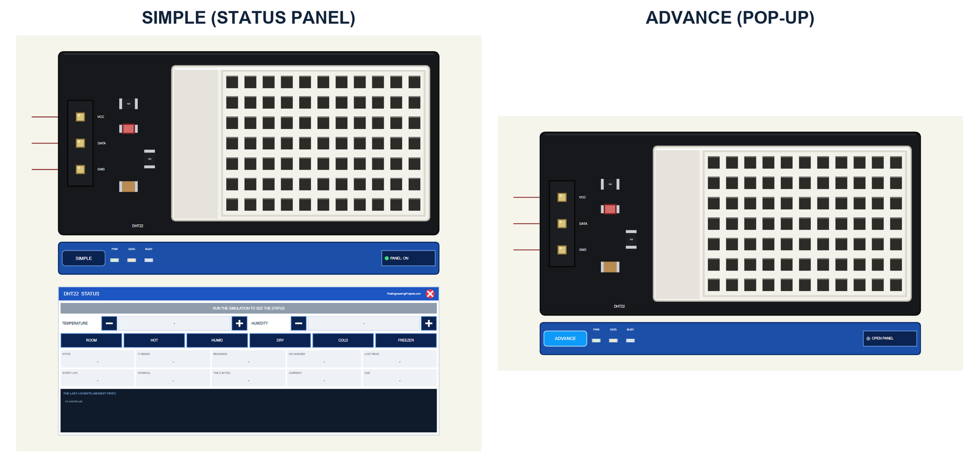
| Simple | Advance | |
|---|---|---|
| Devices | DHT11TEP, DHT22TEP | DHT11ADVTEP, DHT22ADVTEP |
| On the schematic | The module, its strip and the STATUS panel | The module and its strip |
| The air | TEMPERATURE and HUMIDITY - / + and six presets on the panel | The same in the pop-up |
| Status | Banner, 10 readouts, the last 4 events | A pop-up: Sensor, Event log, Tests |
| Interaction | The panel's buttons, PANEL on the strip | The pop-up, OPEN PANEL on the strip |
Download DHT11 / DHT22 Library for Proteus
Click the button below to download DHT11-DHT22-Library-for-Proteus-v1.0.zip (about 1.26 MB, without the C++ source code of the model):
DHT11 / DHT22 Library for Proteus V1.0: Temperature Humidity Sensor- README.txt: the devices, installation, the demo, wiring, the test tools and real hardware.
- Proteus Library Files:
TEPDHT.LIBandArduinoV4TEP.LIBfrom our Arduino Library for Proteus V4.0. - Proteus Model Files:
TEPDHT.DLLandTEPARDUINO.DLL. - Proteus Simulation:
DHT11-DHT22-ArduinoUnoV4.pdsprj,DHT_Demo.hexand copies of the two DLLs. - Arduino Code:
DHT_Demo.ino. It needs the DHT sensor library from the Library Manager of the Arduino IDE, only if you want to change the sketch.
No Proteus yet? Read How to Download and Install Proteus 7 and 8. New to libraries? Follow How to Install a New Library in Proteus.
How to Install DHT11 / DHT22 Library for Proteus
- Close Proteus and extract the whole zip file, for example to your Desktop.
- Copy the two files from Proteus Library Files into the LIBRARY folder of Proteus (usually
C:\Program Files (x86)\Labcenter Electronics\Proteus 8 Professional\LIBRARY). - Copy
TEPDHT.DLLandTEPARDUINO.DLLfrom Proteus Model Files into the MODELS folder. - Delete
TEPDHT.IDXfrom the LIBRARY folder if it is there. - Start Proteus, press P and search for DHT.
Tip: keep the Proteus Simulation folder together, because the project needs its .hex file and the DLLs beside it. The library is tested in Proteus 8.5; Proteus 7 is not supported.
The DHT Modules in Proteus
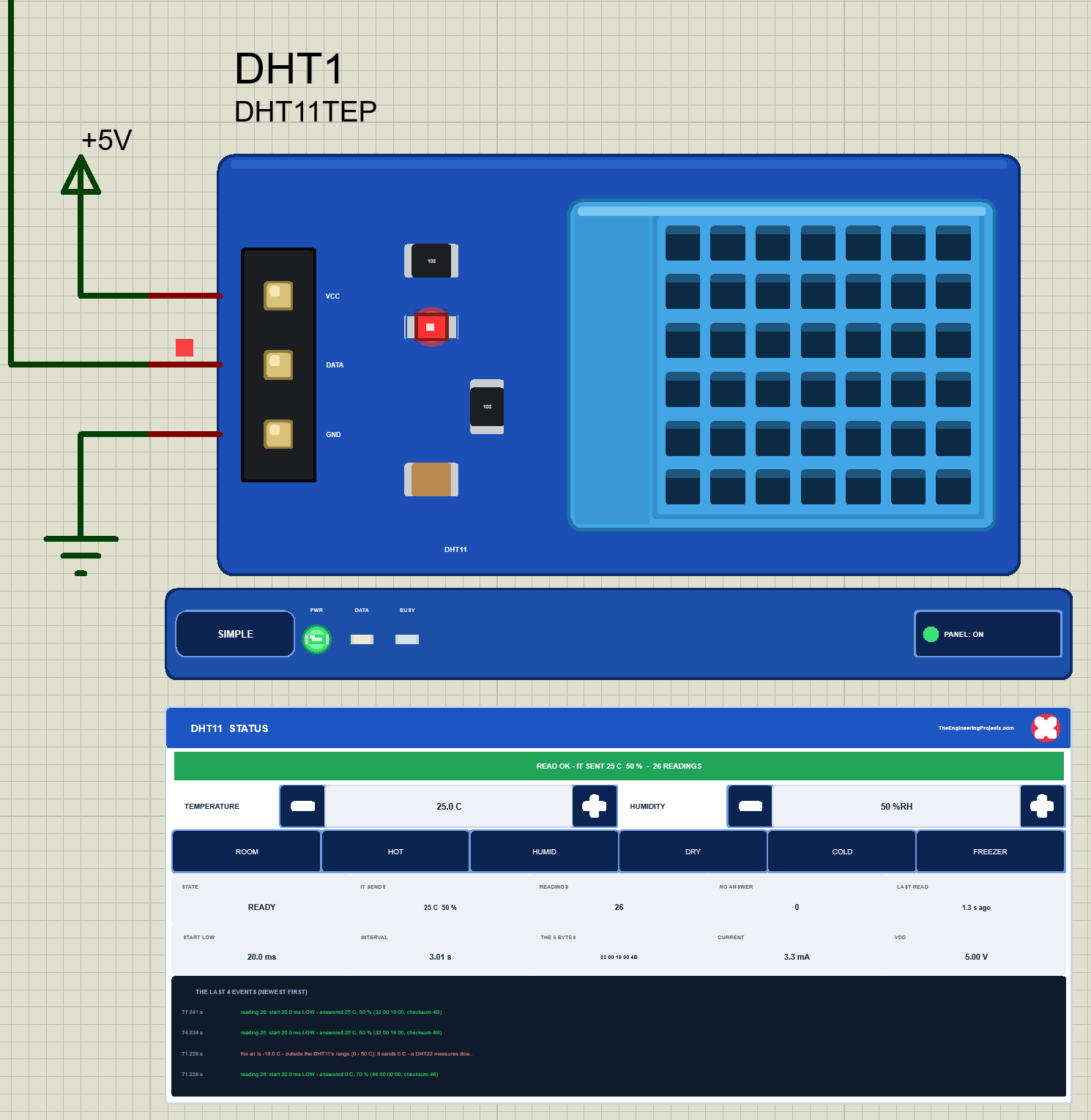
While the simulation runs, the module's red power LED lights. Under the board is the TEP strip with the SIMPLE or ADVANCE badge and three LEDs: PWR while the module has its supply, DATA right after the sensor has sent an answer, and BUSY while the sensor measures and would not answer. The strip, its LEDs and the panels are TEP additions; the real modules have none of them.
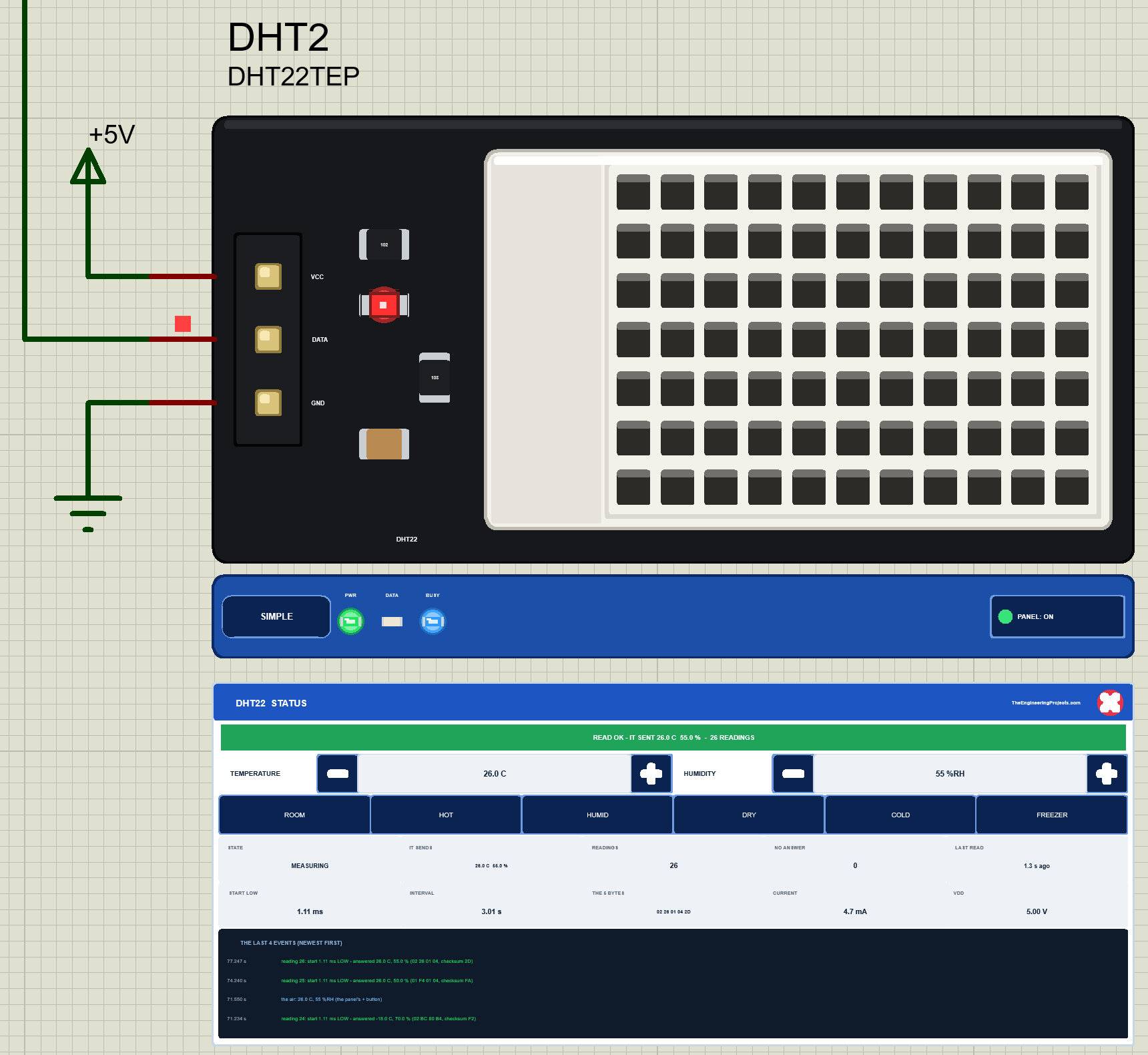
The Simple device adds the STATUS panel. Its banner says what happened last, for example "READ OK - IT SENT 26.0 C 55.0 % - 26 READINGS", and turns red with a warning. Under it are the air controls: TEMPERATURE with its - and + buttons (1 C a click), HUMIDITY with its own (5 % a click), and six presets: ROOM, HOT, HUMID, DRY, COLD and FREEZER. Ten readouts follow: the state (READY, MEASURING, SENDING), what the sensor sent, the readings and how many got no answer, the last reading, the start signal's LOW time, the interval between readings, the 5 bytes, the current and VDD. At the bottom are the last four events. The red X closes the panel, and the PANEL button on the strip opens it again.
The Advance device keeps the schematic clean: only the module and its strip. Its live data and its air controls open in a pop-up window at Run, and the OPEN PANEL button brings the window back if you close it. Three properties set the start: TEMPERATURE (24.0 C by default), HUMIDITY (50 %RH) and, on the Simple devices, PANEL (open or closed).
The Demo Circuit
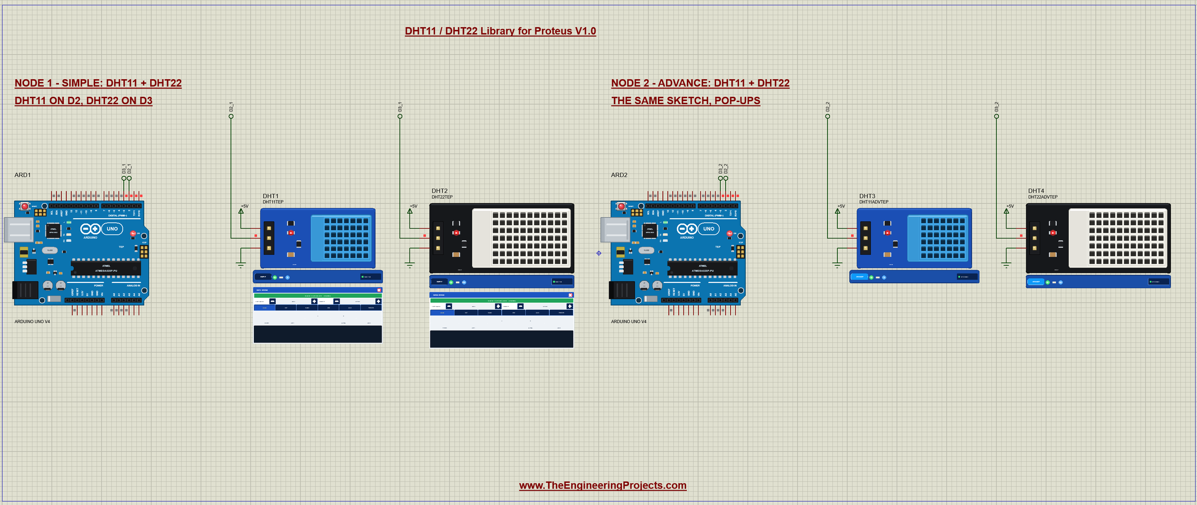
The demo project has two nodes. Each one is an Arduino UNO V4.0 from our Arduino UNO Library for Proteus V4.0 with both sensors: the DHT11 on D2 and the DHT22 on D3. Both UNOs run the same DHT_Demo.hex. Node 1 uses the Simple devices, so you see everything on the schematic; node 2 uses the Advance devices with their pop-ups.
Wiring
| DHT module | Arduino UNO | Note |
|---|---|---|
| VCC | 5V | 3.3 V works too |
| DATA | D2 (the DHT11) / D3 (the DHT22) | any digital pin; the module has its 10 kohm pull-up |
| GND | GND | common ground |
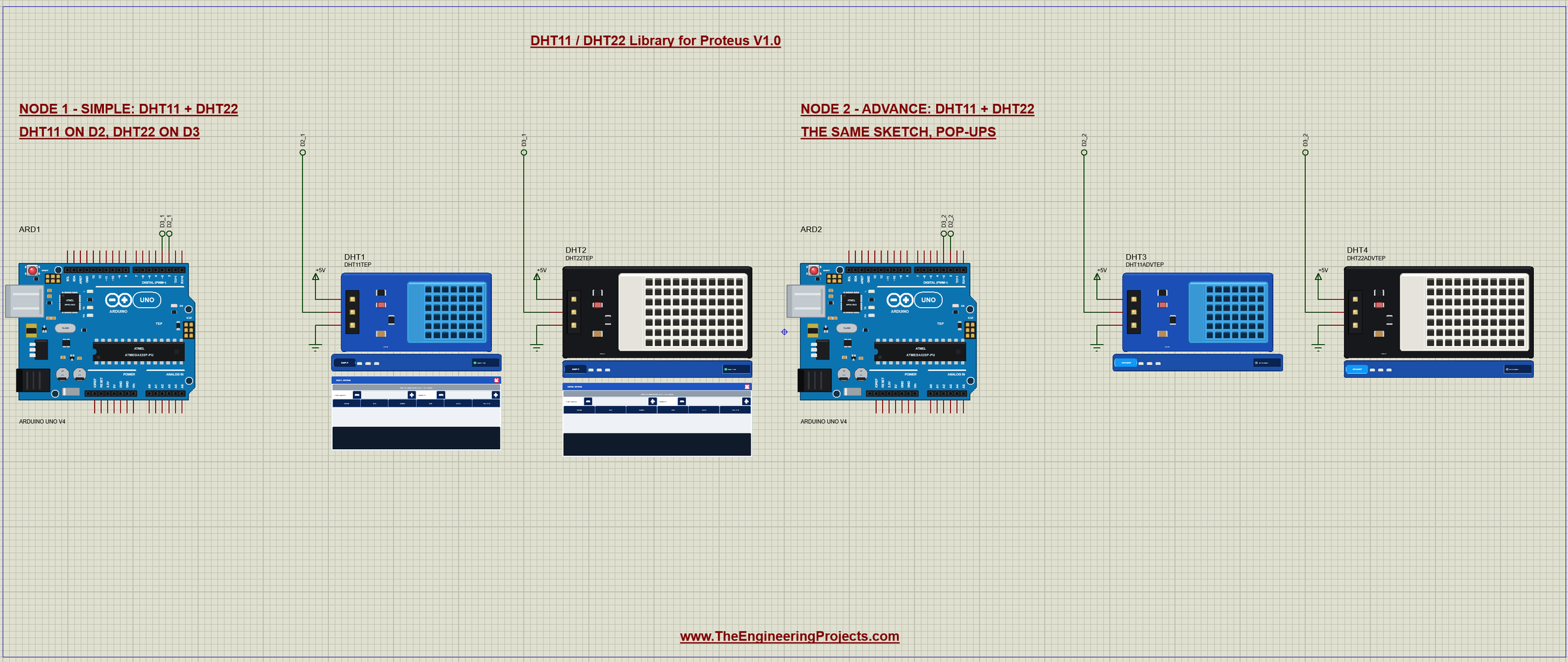
In Proteus every DATA pin reaches its UNO through a wire with a net label: D2_1 and D3_1 for node 1, D2_2 and D3_2 for node 2. Each module gets its 5V from a +5V terminal and its GND from a ground terminal. The serial monitor needs no wires at all, because it is built into the UNO V4.0. A bare 4-pin sensor without a board would need its own 4.7 to 10 kohm pull-up from DATA to VCC; the modules have it.
Node 1: the Simple Modules
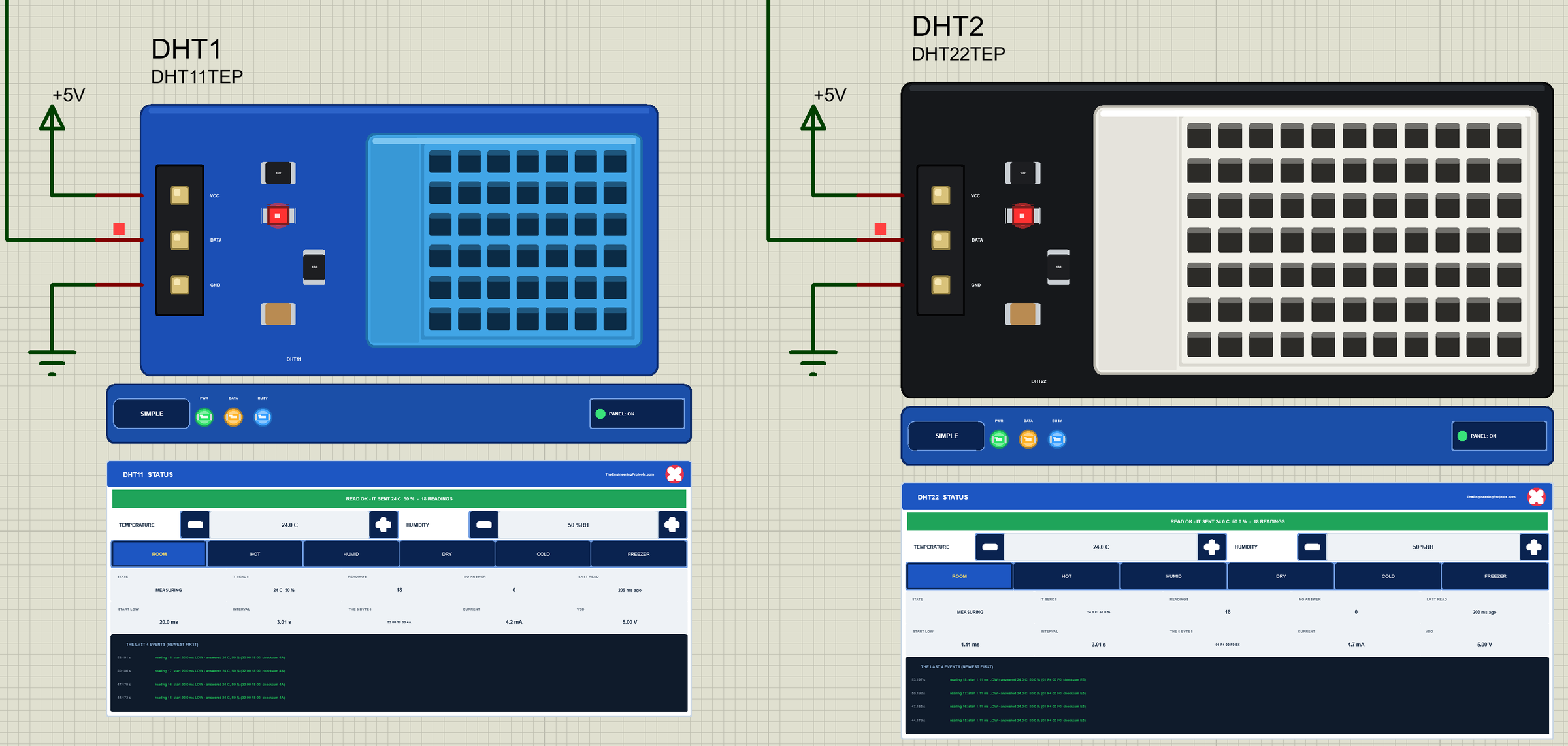
Node 1 shows the whole story on the schematic. Every 3 seconds the UNO reads both sensors, and you can watch the panels count the readings, show the start signal (20.0 ms for the DHT11, 1.11 ms for the DHT22) and the five bytes of each answer.
The Arduino Code
The demo sketch uses the Adafruit DHT sensor library (version 1.4.6), the most common way to read these sensors. New to Arduino? Start with Arduino Tutorial for Beginners and Introduction to Arduino UNO. The sketch begins with its pins and four DHT objects: the right type for each sensor, and the wrong one for the classic mistake:
const uint8_t DHT11_PIN = 2;                   // the DHT11 module's DATA
const uint8_t DHT22_PIN = 3;                   // the DHT22 module's DATA
const unsigned long PERIOD = 3000;             // ms between two readings (a DHT22 needs at least 2 s, a DHT11 1 s)

DHT dht11(DHT11_PIN, DHT11);                   // the right type for each sensor ...
DHT dht22(DHT22_PIN, DHT22);
DHT wrong11(DHT11_PIN, DHT22);                 // ... and the classic mistake: the wrong type
DHT wrong22(DHT22_PIN, DHT11);
The type matters more than it looks. It sets how long the library holds DATA LOW for the start signal, 20 ms for a DHT11 and 1.1 ms for a DHT22, and how it turns the five bytes into numbers. In setup() every object starts with begin(), which makes the pin an input with its pull-up:
dht11.begin(); dht22.begin(); wrong11.begin(); wrong22.begin();Reading is two calls per sensor. The first one does the real reading; the second one, within 2 seconds, gets the same data from the library's memory. A failed reading comes back as NaN:
    const float t11 = dht11.readTemperature(), h11 = dht11.readHumidity();   // one reading: the second call returns the same data
    const float t22 = dht22.readTemperature(), h22 = dht22.readHumidity();
    Serial.print(F("  DHT11: ")); printReading(t11, h11);
    Serial.print(F("   DHT22: ")); printReading(t22, h22);
The values are printed with one decimal, or "failed (NaN)" when the reading did not work:
void printReading(float t, float h) {          // "24.6 C 51.3 %" or "failed (NaN)"
  if (isnan(t) || isnan(h)) { Serial.print(F("failed (NaN)")); return; }
  Serial.print(t, 1); Serial.print(F(" C ")); Serial.print(h, 1); Serial.print(F(" %"));
}
The loop reads both sensors every 3 seconds, comfortably more than the 2 seconds a DHT22 needs:
if (running && (long)(millis() - nextAt) >= 0) { nextAt = millis() + PERIOD; readBoth(); }The commands make the classic mistakes on purpose. WRONG switches to the objects with the wrong types, from the next reading on, 3 seconds after the last one:
  else if (!strcmp(s, "WRONG")) {                // the next reading at its usual time: 3 s after the last one
    running = true; wrongTypes = true;
    Serial.println(F("WRONG: DHT dht(2, DHT22) on the DHT11, dht(3, DHT11) on the DHT22"));
From then on the sketch reads D2 with the DHT22 object and D3 with the DHT11 object:
    const float t11 = wrong11.readTemperature(), h11 = wrong11.readHumidity();   // the DHT11 read as a DHT22
    const float t22 = wrong22.readTemperature(), h22 = wrong22.readHumidity();   // the DHT22 read as a DHT11
FAST forces six readings of the DHT22 half a second apart. dht.read(true) skips the library's 2-second guard, so the sketch really asks the sensor every time:
  for (uint8_t k = 1; k <= 6; ++k) {
    const bool answered = dht22.read(true);
    Serial.print(F("  FAST ")); Serial.print(k); Serial.print(F(": "));
    if (answered) { ++ok; printReading(dht22.readTemperature(), dht22.readHumidity()); } else Serial.print(F("no answer - the DHT22 is still measuring"));
    Serial.println();
    delay(500);
  }
The HEX file is in the package, so you do not need the Arduino IDE to run the demo. To change the sketch, install "DHT sensor library" by Adafruit from the Library Manager (it also asks for "Adafruit Unified Sensor"), open the sketch in the Arduino IDE and export the compiled binary, as in How to get the HEX file from Arduino. It needs 7,662 bytes of flash and 345 bytes of RAM.
The Serial Monitor
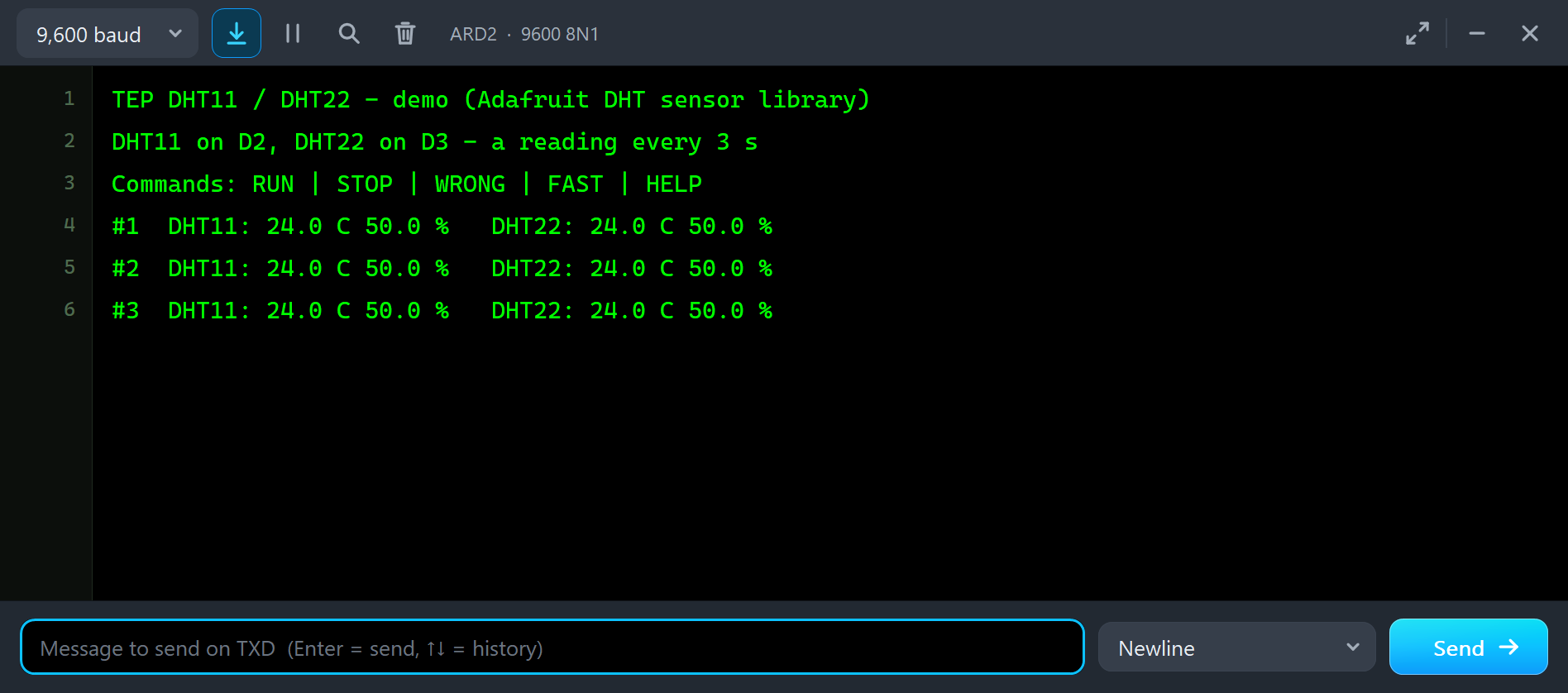
Both UNOs have the serial monitor built in, and it opens at Run. The screenshots use its Simple interface. Each node starts like this:
TEP DHT11 / DHT22 - demo (Adafruit DHT sensor library)
DHT11 on D2, DHT22 on D3 - a reading every 3 s
Commands: RUN | STOP | WRONG | FAST | HELP
#1  DHT11: 24.0 C 50.0 %   DHT22: 24.0 C 50.0 %
#2  DHT11: 24.0 C 50.0 %   DHT22: 24.0 C 50.0 %
#3  DHT11: 24.0 C 50.0 %   DHT22: 24.0 C 50.0 %
The DHT11 prints 24.0 too, because the sketch prints one decimal; the sensor itself sent whole numbers. Type a command in the monitor and press Enter: STOP stops the readings, RUN starts them again with the right types, WRONG and FAST make the mistakes below, and HELP lists them all.
The Advance Pop-Up Window
At Run, each Advance device opens its own window, named after its module, for example DHT22 (AM2302) Sensor Module, with the look of our TEP Serial Monitor Advance for Proteus. It has three tabs, Sensor, Event log and Tests, plus Settings and Help behind the gear and question mark icons. The status bar at the bottom always shows the air, what the sensor sent, the readings and VDD.
The Sensor Page
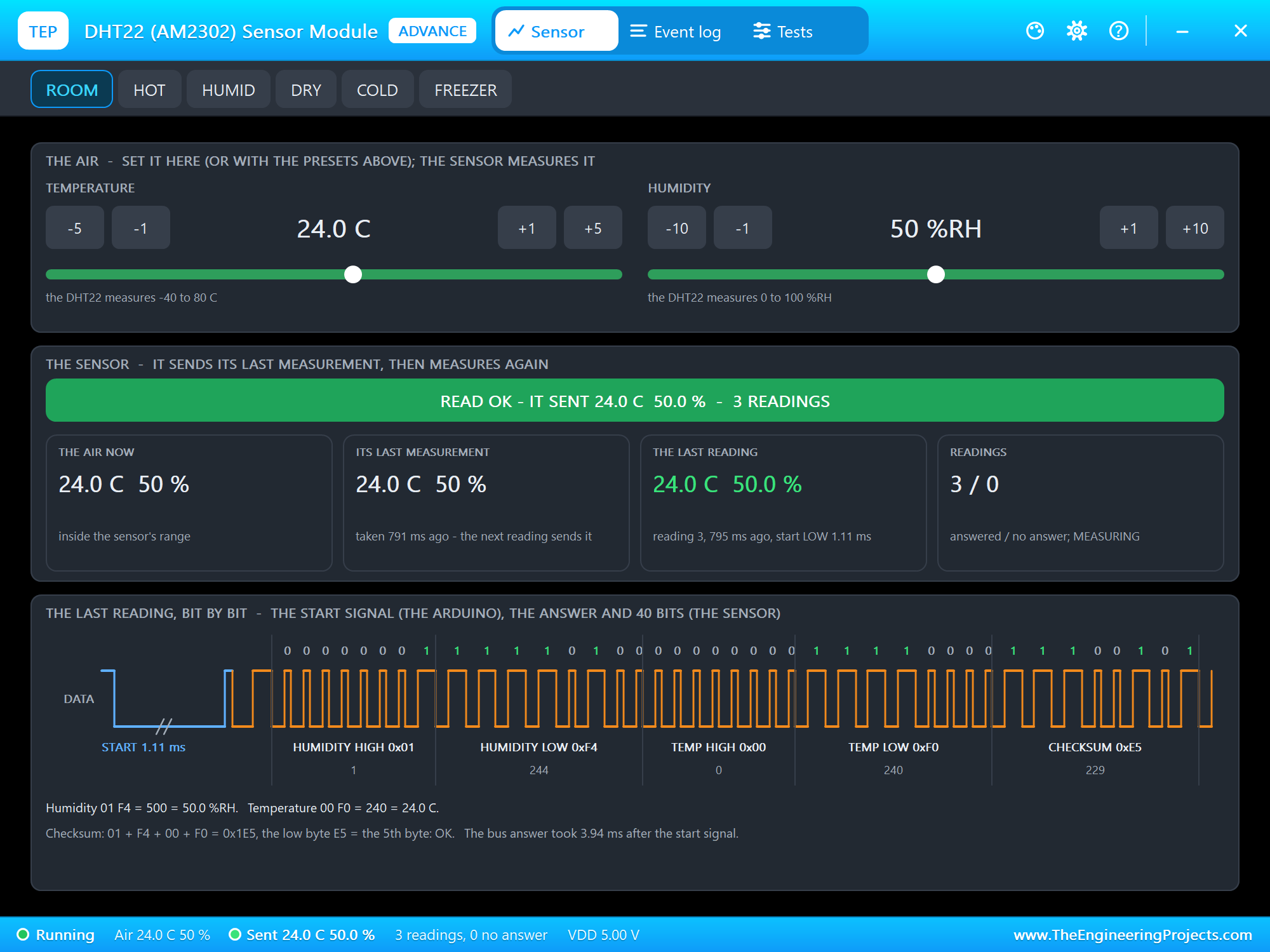
The top card is the air. The presets sit on the toolbar; under the card's title are -5, -1, +1 and +5 C for the temperature and -10, -1, +1 and +10 %RH for the humidity, each with a scale that shows the sensor's range in green. The middle card is the sensor: the banner, the air now, its last measurement (the values the next reading will send), the last reading and the readings answered and not answered.
The bottom card is the best part: the last reading, bit by bit. In blue is the Arduino's start signal, here 1.11 ms LOW, drawn short. In orange is the sensor's answer, to scale: the 80 us LOW and HIGH, then the 40 bits, each labelled 0 or 1, grouped into the five bytes. For 24.0 C and 50.0 % the DHT22 sent HUMIDITY 01 F4, which is 500 or 50.0 %RH, TEMP 00 F0, which is 240 or 24.0 C, and the checksum E5, the low byte of 01 + F4 + 00 + F0 = 0x1E5. The page also says how long the answer took: 3.94 ms.
The Event Log
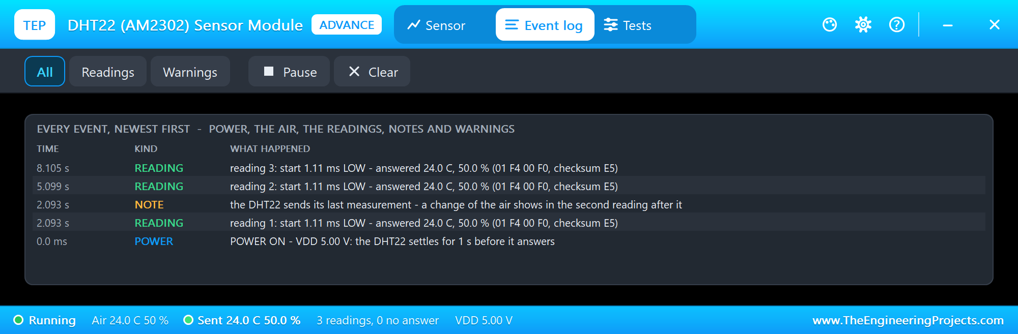
The Event log lists everything that happened, newest first. At 0.0 ms the module gets its power: "the DHT22 settles for 1 s before it answers". The first reading comes at 2.093 s: "reading 1: start 1.11 ms LOW - answered 24.0 C, 50.0 % (01 F4 00 F0, checksum E5)", followed by the note "the DHT22 sends its last measurement - a change of the air shows in the second reading after it". Filter the log by readings or warnings, pause it, or clear it.
Change the Air: the Last Measurement
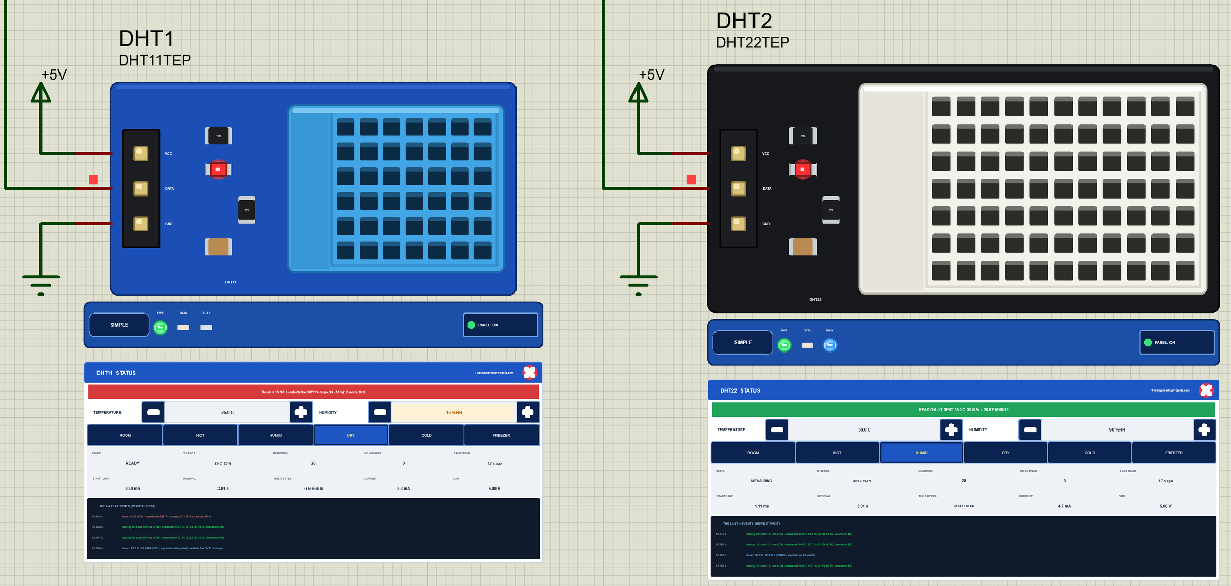
Now let's change the air. On node 1 we clicked DRY on the DHT11's panel and HUMID on the DHT22's panel, with the mouse, while the simulation ran:
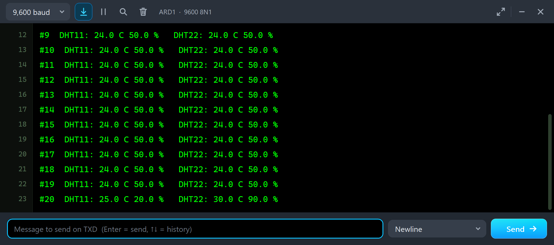
#18  DHT11: 24.0 C 50.0 %   DHT22: 24.0 C 50.0 %
#19  DHT11: 24.0 C 50.0 %   DHT22: 24.0 C 50.0 %
#20  DHT11: 25.0 C 20.0 %   DHT22: 30.0 C 90.0 %
Reading 19 came after the clicks, but it still shows 24.0 C and 50.0 %. That is the last measurement at work: the sensors measured right after reading 18 and sent that. Reading 20 shows the new air: 30.0 C and 90.0 % on the DHT22, and 25.0 C and 20.0 % on the DHT11. The air was 15 %RH, but the DHT11 cannot measure below 20 %, so it sends 20, the end of its range, and its banner says so in red.
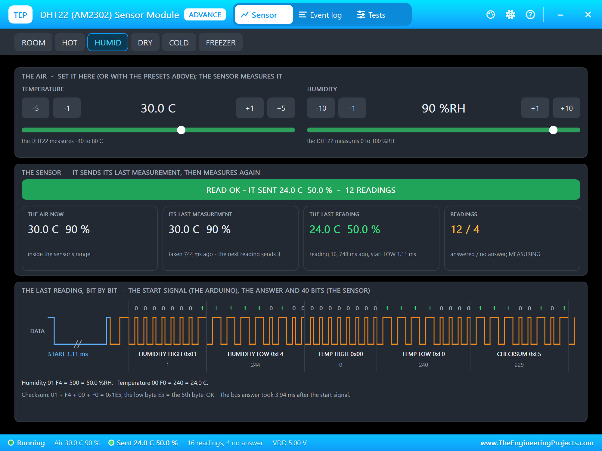
The pop-up shows the same thing in one picture. We clicked HUMID in DHT4's pop-up, and the next reading still sent 24.0 C and 50.0 %. The tiles explain why: the air is 30.0 C and 90 %, the sensor's last measurement is already 30.0 C and 90 %, taken right after that reading, and "the next reading sends it". On a real sensor the effect is bigger, because it also needs seconds to minutes to follow the air; the model follows it at once and keeps only the one-reading lag.
Classic DHT Mistakes, Simulated
The demo sketch can make the most common DHT mistakes on purpose, so you can see what they look like before they happen on your desk. All of them were run in the final test.
The Wrong Type in the Sketch
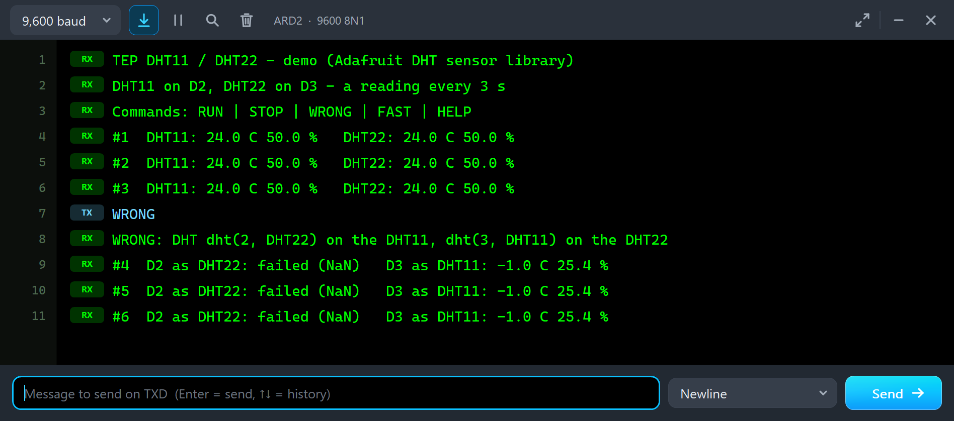
WRONG
WRONG: DHT dht(2, DHT22) on the DHT11, dht(3, DHT11) on the DHT22
#4  D2 as DHT22: failed (NaN)   D3 as DHT11: -1.0 C 25.4 %
#5  D2 as DHT22: failed (NaN)   D3 as DHT11: -1.0 C 25.4 %
#6  D2 as DHT22: failed (NaN)   D3 as DHT11: -1.0 C 25.4 %
This mistake has two faces. The DHT11 read as a DHT22 gets a start signal of only 1.1 ms. A DHT11 needs at least 18 ms, so it never answers, and the library returns NaN: the famous "Failed to read from DHT sensor!". The DHT22 read as a DHT11 is worse, because it seems to work: the DHT22 answers the 20 ms start, but the library decodes its bytes the DHT11 way and prints -1.0 C and 25.4 % for 24.0 C and 50 %. No error, just wrong numbers.
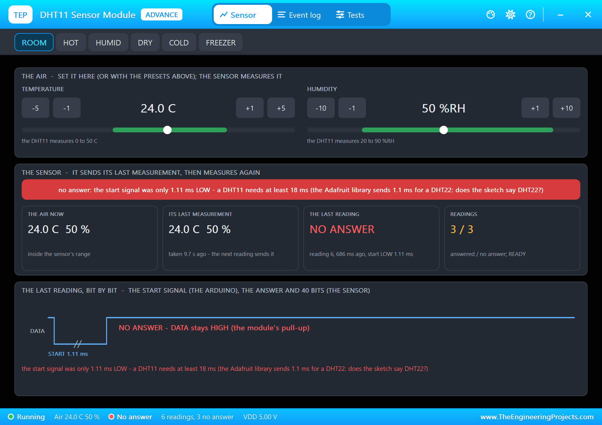
The DHT11's pop-up says exactly what happened: "no answer: the start signal was only 1.11 ms LOW - a DHT11 needs at least 18 ms (the Adafruit library sends 1.1 ms for a DHT22: does the sketch say DHT22?)". The trace shows the short start signal and then nothing: DATA stays HIGH, held by the module's pull-up.
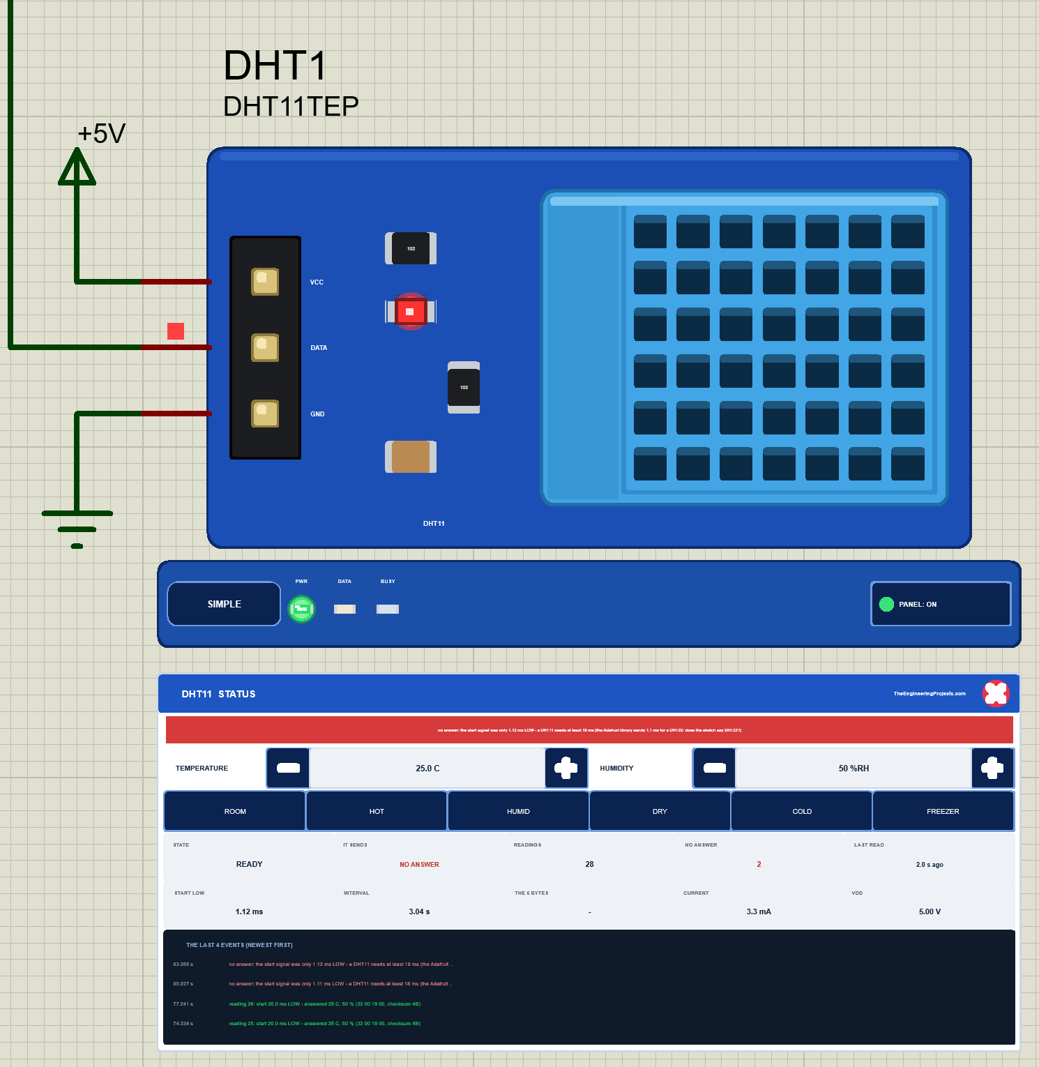
On node 1 the Simple panel tells the same story: the banner in red, NO ANSWER as the last value, the count of readings without an answer, and the start LOW of 1.12 ms. The DHT22 next to it answers, but its events note that its start signal was 20.0 ms, the Adafruit library's start for a DHT11: a hint that the sketch has the wrong type.
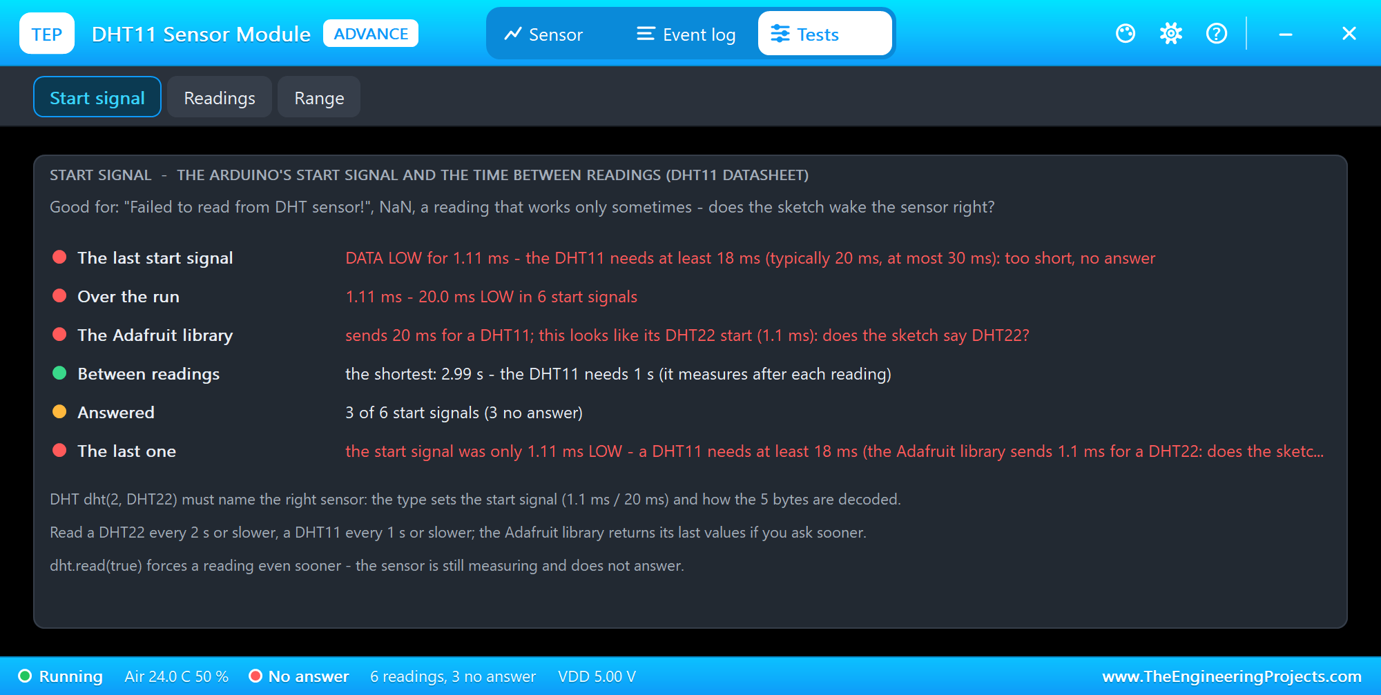
The Start signal tool is the one to open for any "Failed to read". It checks the last start signal against the datasheet, shows the range over the run, compares it with what the Adafruit library sends for this type, checks the shortest time between readings and counts the answers. Here four rows are red, and the advice is right there: "this looks like its DHT22 start (1.1 ms): does the sketch say DHT22?"
Reading Too Often
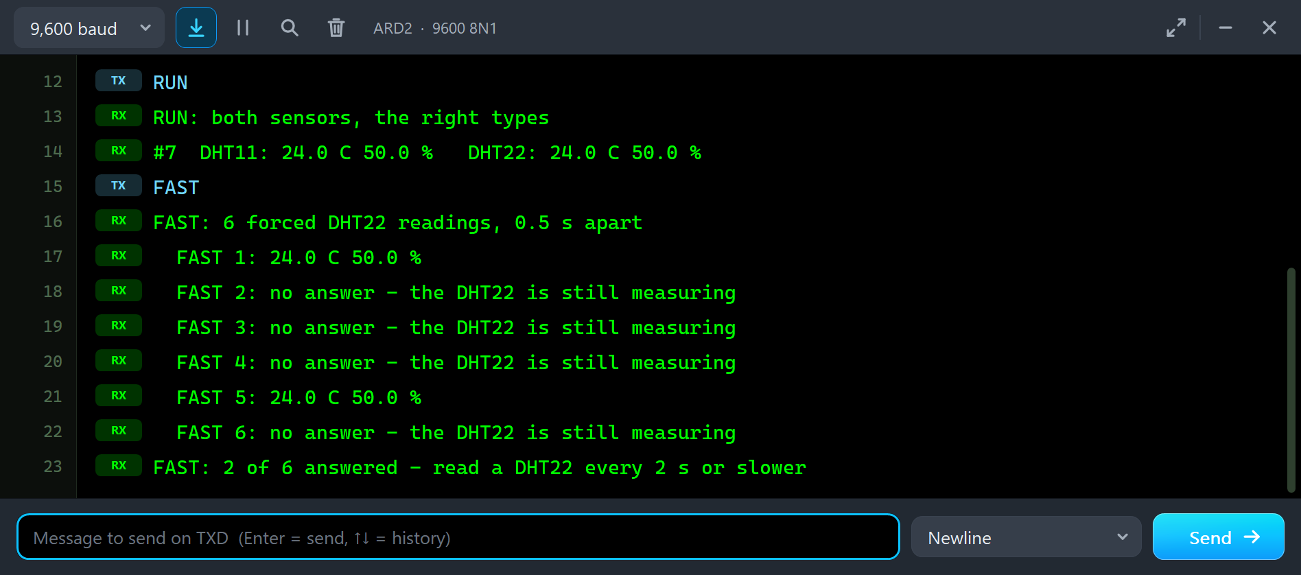
FAST
FAST: 6 forced DHT22 readings, 0.5 s apart
  FAST 1: 24.0 C 50.0 %
  FAST 2: no answer - the DHT22 is still measuring
  FAST 3: no answer - the DHT22 is still measuring
  FAST 4: no answer - the DHT22 is still measuring
  FAST 5: 24.0 C 50.0 %
  FAST 6: no answer - the DHT22 is still measuring
FAST: 2 of 6 answered - read a DHT22 every 2 s or slower
FAST asks the DHT22 every half second with dht.read(true). The first reading works, because the last one was more than 2 seconds before. The next three find the sensor still measuring, and it does not answer. The fifth comes 2 seconds after the first and works again. The Adafruit library normally protects you: without true it hands back its last values when you ask sooner than 2 seconds. Other libraries and hand-written code do not, and then readings fail now and then.
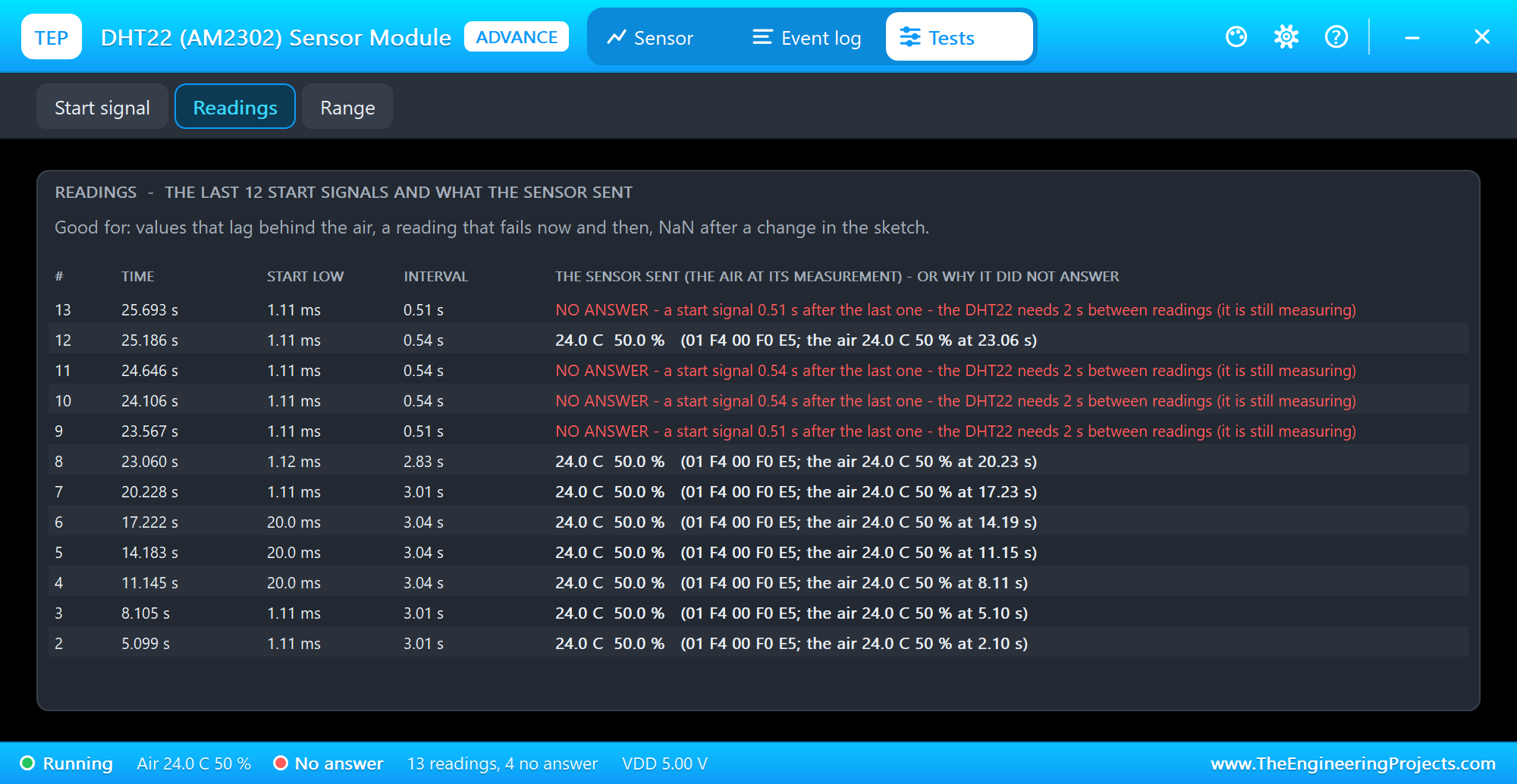
The Readings tool lists the last 12 start signals. Each row has the time, the start LOW, the interval and what the sensor sent, with the air at the moment of its measurement, or the reason it did not answer: "a start signal 0.51 s after the last one - the DHT22 needs 2 s between readings (it is still measuring)". Readings 4 to 6 show a start of 20.0 ms: those were the WRONG readings with the DHT11 object.
Below 0 C: the DHT11's Range
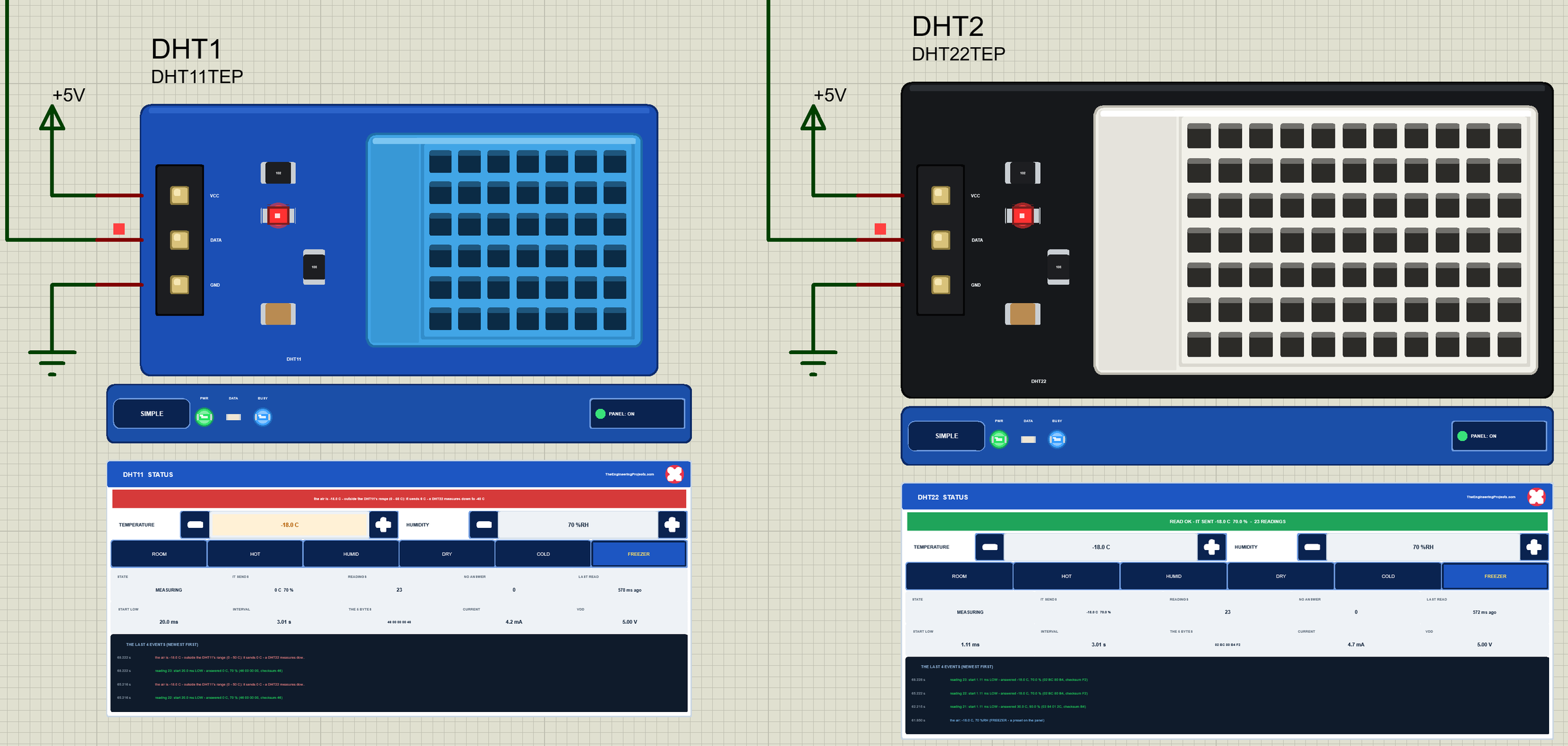
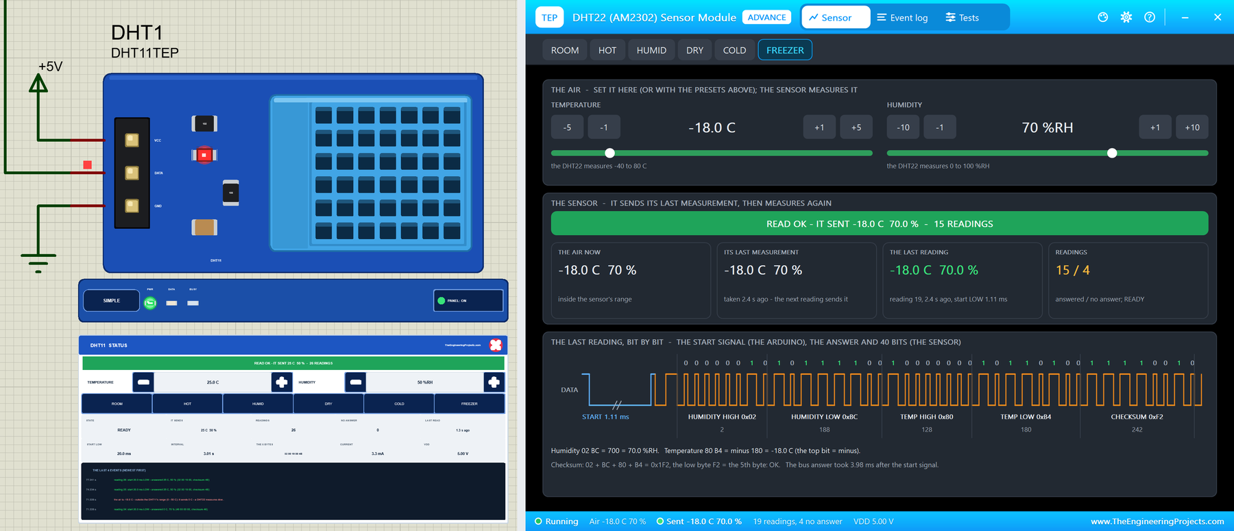
A freezer is a classic DHT project, and a classic disappointment with a DHT11. We clicked FREEZER (-18 C, 70 %RH) on both panels. The DHT11's banner turns red: "the air is -18.0 C - outside the DHT11's range (0 - 50 C): it sends 0 C - a DHT22 measures down to -40 C". The DHT22 has no problem. Node 2's monitor shows the same with the pop-ups' FREEZER, after the lag of one reading:
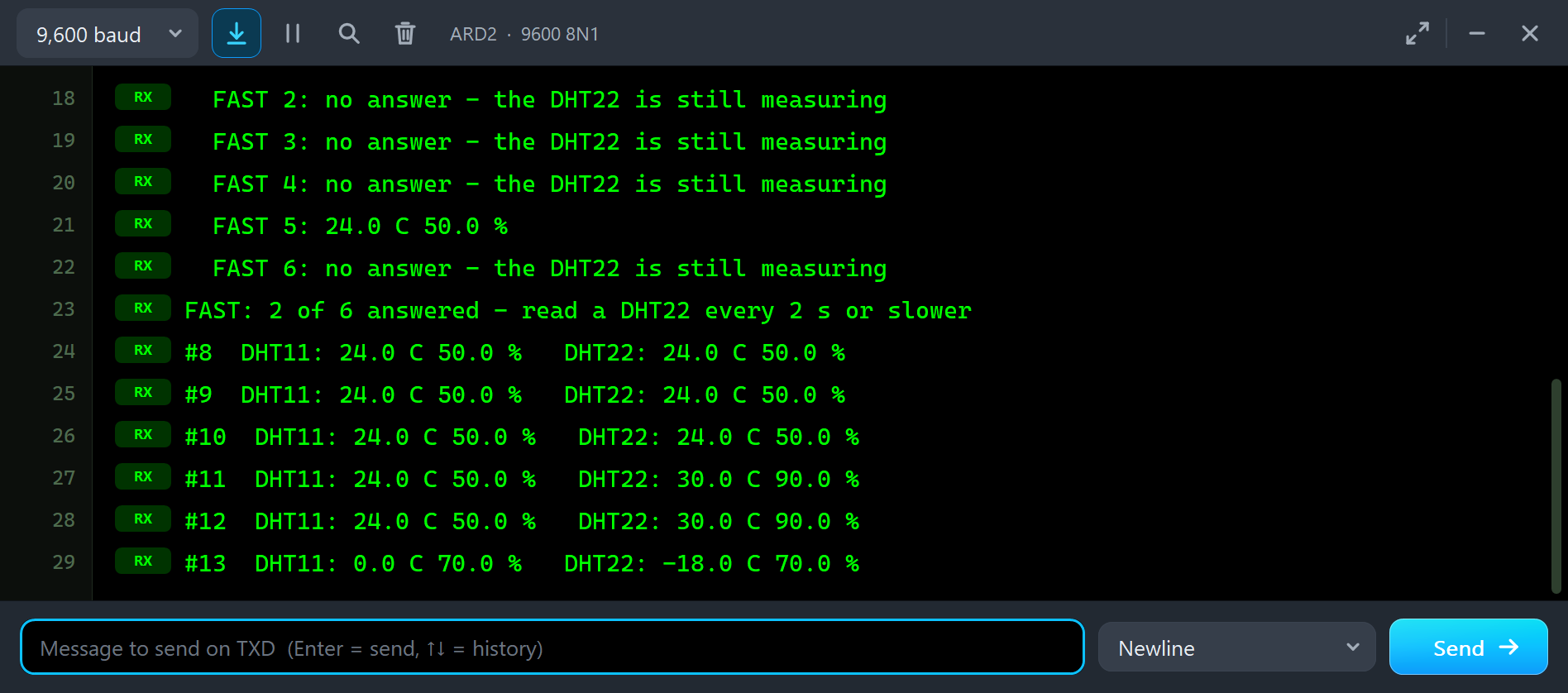
#10  DHT11: 24.0 C 50.0 %   DHT22: 24.0 C 50.0 %
#11  DHT11: 24.0 C 50.0 %   DHT22: 30.0 C 90.0 %
#12  DHT11: 24.0 C 50.0 %   DHT22: 30.0 C 90.0 %
#13  DHT11: 0.0 C 70.0 %   DHT22: -18.0 C 70.0 %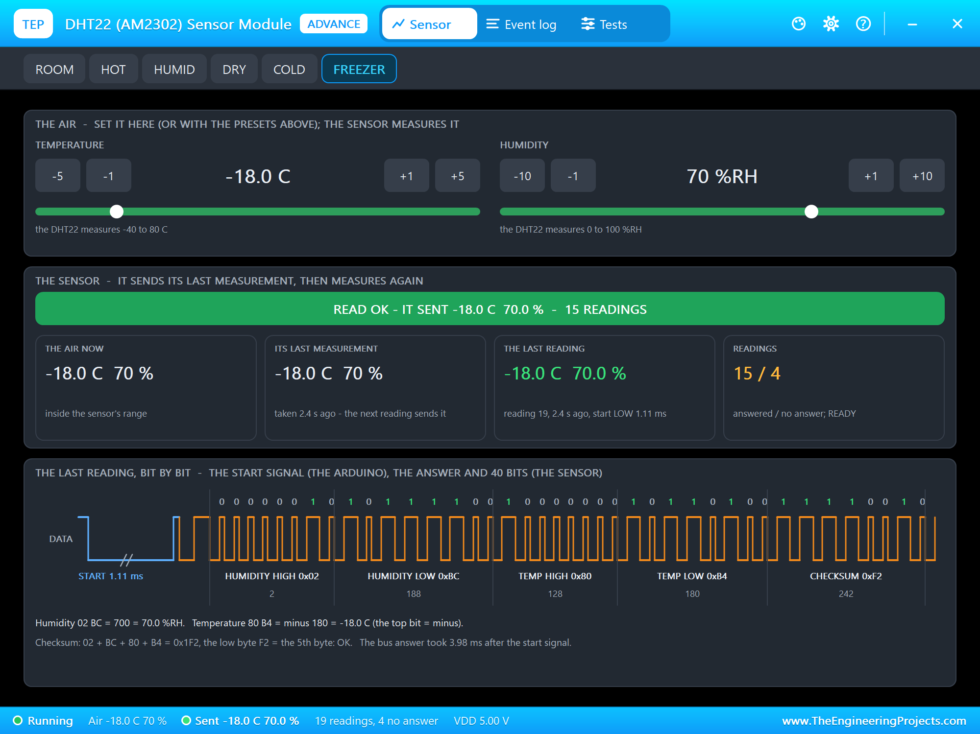
The DHT22's pop-up shows how a negative temperature travels. The temperature bytes are 80 B4: B4 is 180, which is 18.0 C, and the top bit of 80 means minus. The Adafruit library knows this rule and prints -18.0. The checksum is still the low byte of the sum: 02 + BC + 80 + B4 = 0x1F2, so F2.
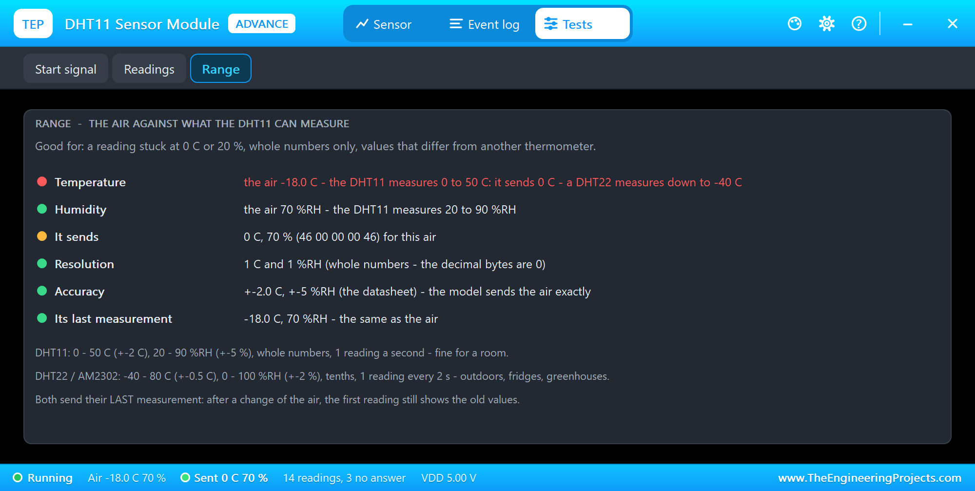
The Range tool puts the air next to what the sensor can measure: the temperature and the humidity against its range, what it sends for this air (46 00 00 00 46 here: 70 % and 0 C), the resolution (whole numbers on the DHT11, tenths on the DHT22), the datasheet's accuracy, and whether its last measurement is still behind the air.
The Simulation Log
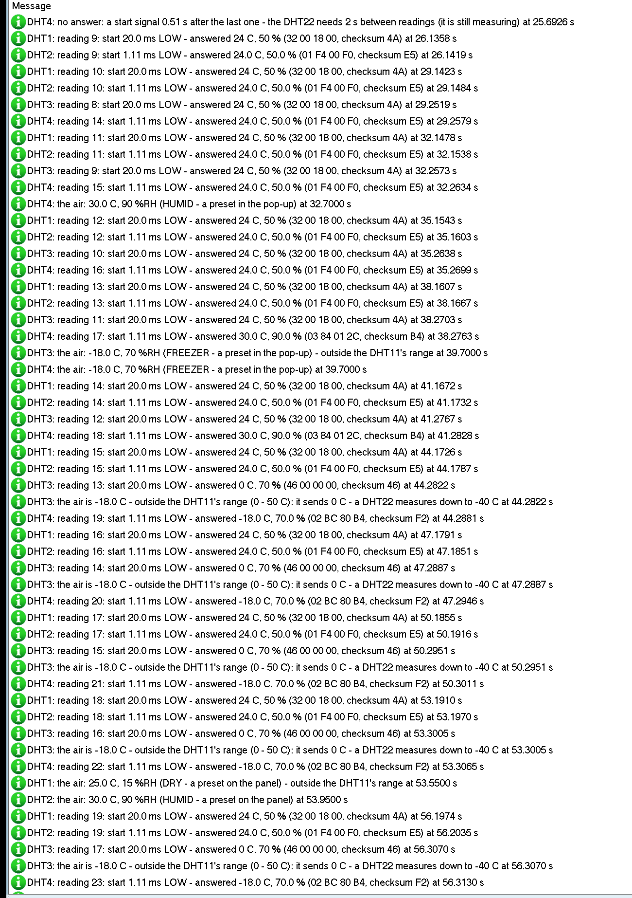
Every module also writes to the simulation log of Proteus, with the exact simulation time. This part shows the lag and the freezer on node 2:
DHT4: the air: 30.0 C, 90 %RH (HUMID - a preset in the pop-up) at 32.7000 s
DHT4: reading 16: start 1.11 ms LOW - answered 24.0 C, 50.0 % (01 F4 00 F0, checksum E5) at 35.2699 s
DHT4: reading 17: start 1.11 ms LOW - answered 30.0 C, 90.0 % (03 84 01 2C, checksum B4) at 38.2763 s
DHT3: the air is -18.0 C - outside the DHT11's range (0 - 50 C): it sends 0 C - a DHT22 measures down to -40 C
      at 44.2822 s
DHT4: reading 19: start 1.11 ms LOW - answered -18.0 C, 70.0 % (02 BC 80 B4, checksum F2) at 44.2881 s
The air changed at 32.7 s, reading 16 still sent 50.0 % (01 F4), and reading 17 sent 90.0 % (03 84). The DHT11 next to it warns about its range, and the DHT22 sends -18.0 C with 80 B4.
How the Model Works
Proteus runs the Arduino's writes to DATA as digital events, each with its exact time. The model watches the DATA line: when the Arduino pulls it LOW and lets it go, the model knows how long the start signal lasted, to the microsecond. If the sensor can answer, the model drives its answer itself, edge by edge, from simulator callbacks at the exact times: LOW is a strong LOW, and "released" is the module's pull-up. The Arduino reads those edges like the real ones.
The values come from the air you set, encoded the way each sensor does it, with the checksum. After each answer the model takes a new measurement of the air and keeps it for the next reading, and it does not answer again until the interval is over. The supply is real too: the power LED and the sensor's current, 50 to 60 uA when idle and 1 to 1.5 mA while it measures, are drawn from VCC.
Troubleshooting
- NaN or "Failed to read": the wrong type in
DHT dht(pin, type), readings more often than every 2 s (DHT22) or 1 s (DHT11), a reading in the first second after power-up, the wrong pin, or no 5V. The Start signal tool says which. - Strange numbers like -1.0 C or 25.4 %: a DHT22 read as a DHT11. Fix the type.
- The reading lags behind the air: normal. The sensor sends its last measurement; the second reading after a change shows it.
- Stuck at 0 C or 20 %: the air is outside the DHT11's range. Use a DHT22.
- Whole numbers only: that is the DHT11. The DHT22 has tenths.
- No part, no answer at all or no monitor: TEPDHT.DLL or TEPARDUINO.DLL is missing from MODELS and the project folder; a closed monitor opens again with a click on the UNO's USB port.
Things to Know Before Using a Real DHT Sensor
- The pull-up: a bare 4-pin sensor needs 4.7 to 10 kohm from DATA to VCC; the modules have it.
- Wait before the first reading: 1 to 2 seconds after power-up, and then read a DHT22 every 2 seconds or slower.
- The interrupts: the Adafruit library turns them off for about 4 ms of each reading, so Serial can lose a character now and then.
- Heat: keep the sensor away from the Arduino's regulator and other warm parts, or it reads too warm.
- Slow response: a real sensor needs seconds to minutes to follow a change of the air, much longer than the one-reading lag.
Limitations of the Simulation
- Not modelled: the sensors' accuracy and noise (the model sends the air exactly), their slow response to a change of the air, self-heating, condensation, long-wire effects and damage from a wrong supply (the model only warns).
- Outside its range a sensor sends its range's end; that is the model's choice, because the datasheets do not say what happens there.
- The DHT11 is the classic one with whole numbers; some newer DHT11s also send tenths of a degree.
- The strips, their LEDs and the panels are TEP additions.
- The model is our own, written from the DHT11 and AM2302 datasheets. This library is not made or endorsed by Aosong, Adafruit, the makers of these modules or Labcenter.
- Licences: the demo sketch uses the DHT sensor library 1.4.6 by Adafruit (MIT), which is not shipped; install it from the Library Manager. The demo's HEX file contains it and the Arduino AVR core 1.8.6 with LGPL-licensed code; the licence text and the source links are in the README.
- Tested in Proteus 8.5 in October 2026 (the demo as shipped on two Arduino UNO V4.0 boards with their built-in monitors: the readings on both nodes, the presets and the - / + buttons with the mouse, the lag, WRONG, FAST, FREEZER, the pop-ups and the three tools; 94.0 s of simulation took 272 s, about 0.35 x real time with both pop-ups and both monitors open). Proteus 7 is not supported.
So, that was all about the DHT11 / DHT22 Library for Proteus V1.0. I hope the start signal, the 40 bits, the last measurement and the ranges of these two little sensors are clear now, so your weather station reads the right values from the first run. If you use the DHT11 / DHT22 Library for Proteus in a project, please share it in the comments or in our forum, and if you have any questions, ask in the comments and I will help you out. Till the next tutorial, take care and have fun!
Comments
0