


BTS7960 Motor Driver Library for Proteus V1.0 (IBT-2, 43A H-Bridge)


Hello friends, I hope you all are doing great. Today, I am going to share the new BTS7960 Motor Driver Library for Proteus V1.0. When a small motor driver is not enough, makers reach for the IBT-2: a red board under a big aluminium heatsink with two BTS7960 half-bridges that switch up to 43 A. It runs the 12 V and 24 V motors of big robots, electric carts, winches and wiper motors, and it can tell your Arduino how much current flows. Now it is ready for your Proteus simulations, together with a 12 V 775 DC motor with a flywheel.
Behind the board sits our own model of the IBT-2: the two half-bridges with their 16 mohm switches, the enables, braking on the low or the high side, coasting, PWM speed control and, most important, the current sense outputs R_IS and L_IS that a real BTS7960 gives you. The motor is a model too, with the resistance, back-EMF, friction and inertia of a 775, so its flywheel spins up, slows under load and draws the currents a real one would. You get three devices: a Simple driver with a live STATUS panel, an Advance driver with a pop-up window and three test tools, and the 775 motor. The demo runs on our Arduino UNO V4.0 with its serial monitor built into the board.
NOTICE: a 43 A driver is only interesting in a simulator if the currents are real. So we did not draw a spinning icon: the motor draws its start current, slows under load, brakes and coasts like a real 775, and the driver reports what its current sense would report. It took our team a lot of hard work. Your feedback is the fuel that keeps us going, so please tell us what you think in the comments below or in the Motor Driver board of our forum. And if our free libraries help you, you can buy us a coffee. So, let's get started with the BTS7960 Motor Driver Library for Proteus V1.0:
What is the BTS7960 Motor Driver?
A motor driver lets a microcontroller switch a motor current that its pins could never carry, in both directions. Most drivers do it with an H-bridge: four switches arranged like the letter H with the motor in the middle. Close the top-left and the bottom-right switch and the current flows through the motor one way; close the other pair and it flows the other way. Close both bottom switches and the motor is shorted, which brakes it.
The BTS7960 from Infineon is one half of that H: a high-side switch to the supply, a low-side switch to GND and the driver logic in one package. Its switches are big MOSFETs with only 16 mohm in the path, so 10 A lose just 0.16 V. The chip protects itself: it limits the current at about 43 A, switches off when it gets too hot and refuses to run below about 5.5 V. Two BTS7960s make a full H-bridge, and that is exactly what the popular IBT-2 module is.
| IBT-2 BTS7960 module | |
|---|---|
| Chips | Two Infineon BTS7960 half-bridges under a finned heatsink, a 74HC244 buffer |
| Motor supply B+ | 6 - 27 V (B- = GND) |
| Logic VCC | 5 V; the inputs work with 3.3 V and 5 V levels |
| Current | 43 A peak (the chip's current limit), 16 mohm path |
| PWM | up to 25 kHz |
| Header | RPWM, LPWM, R_EN, L_EN, R_IS, L_IS, VCC, GND |
| Terminals | B+ / B- (the supply), M+ / M- (the motor) |
| Size | about 50 x 50 mm, 43 mm high with the heatsink |
| Devices in this library | BTS7960TEP (Simple), BTS7960ADVTEP (Advance), MOTOR775TEP (the motor) |
The Truth Table of the IBT-2
Each half-bridge has an input and an enable. RPWM and R_EN drive the M+ output, LPWM and L_EN drive M-. With an enable HIGH, the input HIGH connects the output to B+ and the input LOW connects it to GND. With the enable LOW, that half-bridge sleeps and its output is open.
| RPWM | LPWM | R_EN | L_EN | M+ | M- | The motor |
|---|---|---|---|---|---|---|
| HIGH | LOW | HIGH | HIGH | B+ | GND | Forward |
| LOW | HIGH | HIGH | HIGH | GND | B+ | Reverse |
| LOW | LOW | HIGH | HIGH | GND | GND | Brake (both low sides; also the PWM off time) |
| HIGH | HIGH | HIGH | HIGH | B+ | B+ | Brake (both high sides) |
| any | any | LOW | LOW | open | open | Sleep: the motor coasts |
Note the fourth row. On many motor drivers, driving both inputs HIGH is a short circuit. On the IBT-2 it is not: both outputs simply sit at B+ and the motor is braked through the high-side switches. And with only one enable LOW, that output is open while the other one still drives its side.
Speed Control with PWM
For the speed, the sketch keeps both enables HIGH and gives RPWM a PWM signal with analogWrite() while LPWM stays LOW. During the on time M+ is at B+ and the motor is driven; during the off time both outputs are at GND and the motor is braked, so its speed follows the duty cycle. For reverse, the roles swap. The UNO gives 980 Hz on D5 and D6 and 490 Hz on D3, D9, D10 and D11; the BTS7960 accepts PWM up to 25 kHz.
The Current Sense Outputs
This is the feature that sets the BTS7960 apart. Its IS pin sources a small current that is proportional to the current in its high-side switch: the load current divided by about 8500. Put a 1 kohm resistor from IS to GND and you get a voltage of 1 V for every 8.5 A, which any Arduino analog pin can read. On the IBT-2 the two IS pins are R_IS and L_IS. Only one high side carries current at a time, forward through R and reverse through L, so both pins can share one analog input and one resistor.
Two consequences surprise many people. First, with PWM the high side carries the motor current only during the on time, so the average IS reading is the current taken from the supply, the duty cycle times the motor current. Second, when the motor is braked, or when it feeds current back while slowing down, the current flows through the low-side switches and IS reads zero. In a fault, such as the current limit, IS jumps to about 4.5 mA, which is 4.5 V on a 1 kohm resistor.
The 775 DC Motor
The 775 is a 42 mm brushed DC motor that runs everything from drills and saws to robot drives. The common 12 V version spins at about 10,000 RPM and draws tens of amps when it starts or stalls, a good match for a 43 A driver. Our model carries a 64 mm aluminium flywheel, so you can see the speed change.
| 775 DC motor 12 V (the model) | |
|---|---|
| Rated voltage | 12 V |
| No load | about 10,000 RPM and 0.7 A at 12 V |
| Stall | 30 A at 12 V (0.4 ohm), about 3.4 kg.cm |
| Response | 63 % of its speed in about 0.2 s (with the flywheel) |
| On the schematic | the flywheel turns at the simulated speed; RPM, volts, amps; LOAD button |
What's New in BTS7960 Motor Driver Library for Proteus V1.0
- The real module: the red IBT-2 board with its finned heatsink, the 74HC244, the 8-pin header and the two blue screw terminals, drawn at about 1.1 x its real size.
- Two BTS7960 half-bridges: 8 mohm switches with body diodes drive real current into the motor, and B+ delivers what the motor draws.
- The full truth table: forward, reverse, brake on the low or on the high sides, one side disabled and sleep.
- Current sense: R_IS and L_IS source the high-side current divided by 8500, and the fault current above 43 A.
- Supply checks: B+ under-voltage and over-voltage, VCC, the enables left LOW.
- PWM measured: the frequency and duty of every input and the drive, live.
- A 775 motor with a flywheel that turns at the simulated speed, with RPM, volts, amps and a LOAD button that presses a brake pad on the flywheel.
- Three test tools on the Advance driver: Truth table, PWM and Power.
- A two-node demo on our Arduino UNO V4.0: hard speed steps on one node, soft ramps on the other, both reading the current sense.
- A compact package: about 1.41 MB, without the C++ source code.
Three Devices: Simple, Advance and the Motor
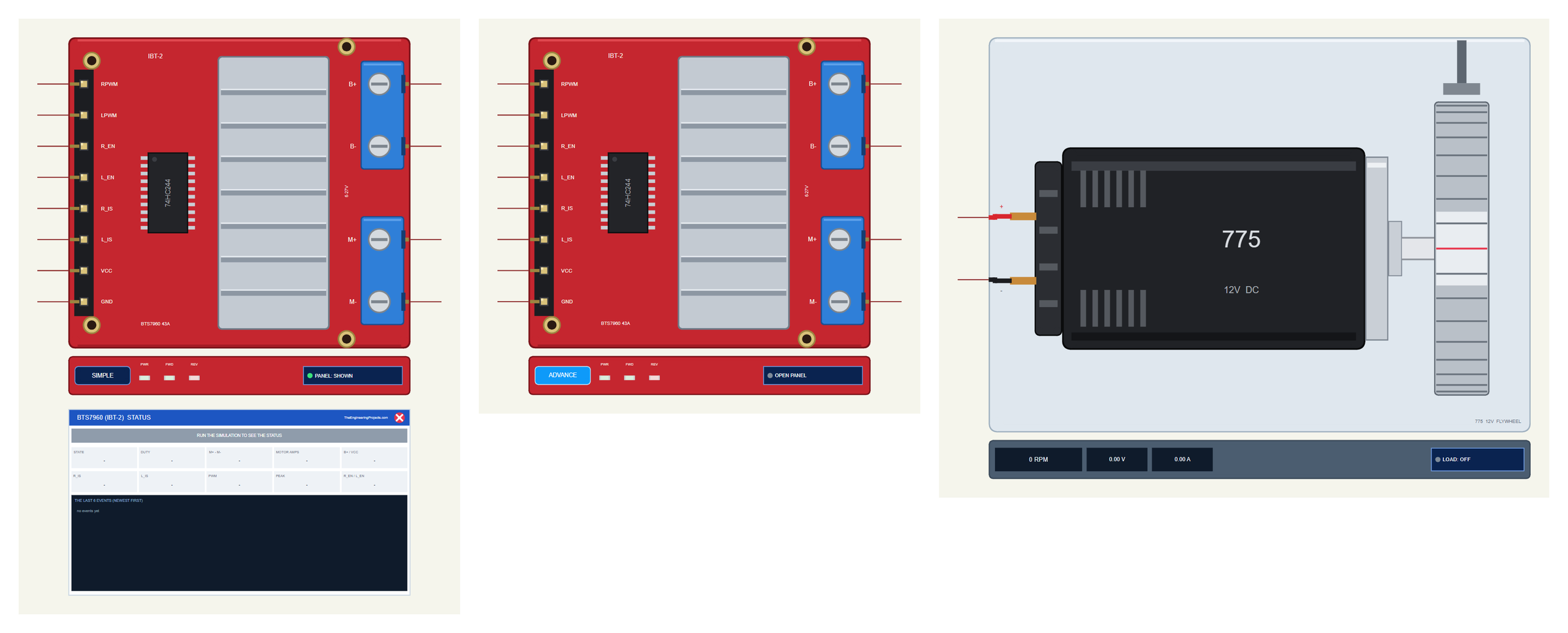
| Simple | Advance | Motor | |
|---|---|---|---|
| Device | BTS7960TEP | BTS7960ADVTEP | MOTOR775TEP |
| Library file | TEPBTS7960.LIB | TEPBTS7960.LIB | TEPMOTOR775.LIB |
| On the schematic | The board + the STATUS panel | The board only | The motor with its flywheel |
| Status | Banner, 10 readouts, the last 6 events | A pop-up: Motor, Event log, Tests | RPM, volts, amps |
| Interaction | PANEL button | OPEN PANEL button | LOAD button, a click on the flywheel |
Download BTS7960 Motor Driver Library for Proteus
Click the button below to download BTS7960-Motor-Driver-Library-for-Proteus-v1.0.zip (about 1.41 MB, without the C++ source code):
BTS7960 Motor Driver Library for Proteus V1.0- README.txt: the devices, installation, the demo, wiring, the test tools and real hardware.
- Proteus Library Files:
TEPBTS7960.LIB,TEPMOTOR775.LIBandArduinoV4TEP.LIBfrom our Arduino Library for Proteus V4.0. - Proteus Model Files:
TEPBTS7960.DLL,TEPMOTOR775.DLLandTEPARDUINO.DLL. - Proteus Simulation:
BTS7960-Motor-Driver-ArduinoUnoV4.pdsprj,BTS7960_Demo.hexand copies of the three DLLs. - Arduino Code:
BTS7960_Demo.ino(no library needed).
No Proteus yet? Read How to Download and Install Proteus 7 and 8. New to libraries? Follow How to Install a New Library in Proteus.
How to Install BTS7960 Motor Driver Library for Proteus
- Close Proteus and extract the whole zip file, for example to your Desktop.
- Copy the three files from Proteus Library Files into the LIBRARY folder of Proteus (usually
C:\Program Files (x86)\Labcenter Electronics\Proteus 8 Professional\LIBRARY). - Copy
TEPBTS7960.DLL,TEPMOTOR775.DLLandTEPARDUINO.DLLfrom Proteus Model Files into the MODELS folder. - Delete
TEPBTS7960.IDXandTEPMOTOR775.IDXfrom the LIBRARY folder if they are there. - Start Proteus, press P and search for BTS7960 and 775.
Tip: keep the Proteus Simulation folder together, because the project needs its .hex file and the DLLs beside it. The library is tested in Proteus 8.5; Proteus 7 is not supported. For smaller motors, see our L9110S Motor Driver Library and TB6612FNG Motor Driver Library.
The IBT-2 Module in Proteus
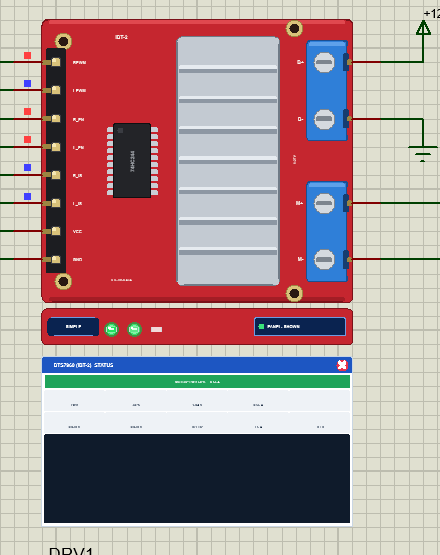
The driver looks like the real IBT-2: the red board, the finned aluminium heatsink over the two BTS7960 chips, the 74HC244 buffer and the 8-pin header on the left, and the two blue screw terminals on the right, B+ and B- for the motor supply above, M+ and M- for the motor below. On the real board the header pins come in the same order: RPWM, LPWM, R_EN, L_EN, R_IS, L_IS, VCC, GND.
Under the board is the TEP strip. The PWR LED is green while both VCC and B+ are in range, so a dark PWR LED tells you at once that a supply is missing. The FWD and REV LEDs show the drive, brighter with more duty. The strip, its LEDs and the panels are TEP additions; a real module has none of them.
The Simple driver adds the BTS7960 (IBT-2) STATUS panel. Its banner says what the motor does and the current it draws, for example "MOTOR: FWD 50 %", or shows SLEEP, NO MOTOR SUPPLY or the latest warning. Ten readouts follow: the state, the duty, the volts across the motor, the motor amps, B+ and VCC, the volts on R_IS and L_IS, the PWM frequency, the peak current and the two enables. At the bottom are the last six events. The red X closes the panel, and the PANEL button on the strip opens it again.
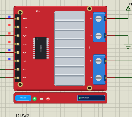
The Advance driver keeps the schematic clean: only the board and its strip. Its live data opens in a pop-up window at Run, and the OPEN PANEL button brings the window back if you close it.
The 775 DC Motor in Proteus
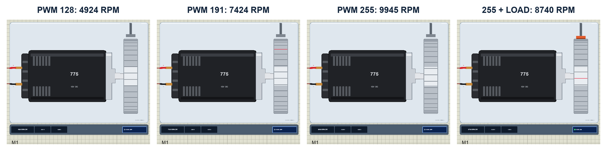
The motor is drawn from above: the brass tabs and the black end cap at the back, the black can with its cooling slots, the silver front bell, the shaft and the aluminium flywheel seen edge-on. While the simulation runs, the knurl lines on the flywheel move at the simulated speed, with a red mark you can follow when it is slow; at full speed the rim becomes a smooth blur, just as your eye sees a real one. The strip under it shows the speed with its direction, for example "9945 RPM CW", the voltage across the motor and its current.
With the demo's 12 V on B+, motor M1 reached 4924, 7424 and 9945 RPM at PWM 128, 191 and 255, and at 50 % it drew 0.65 A with 6.04 V across it. The BTS7960's 16 mohm path loses almost nothing: at full speed 11.99 V of the 12 V reach the motor.
The LOAD Button
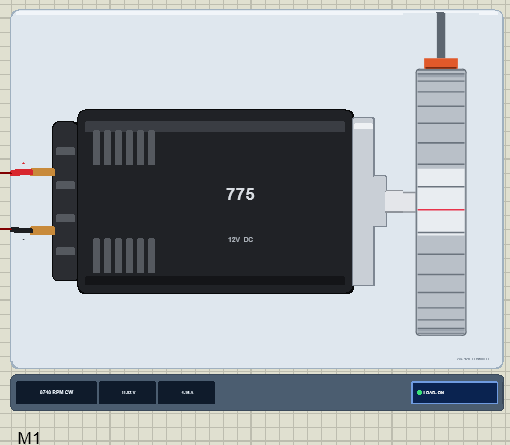
Click LOAD under a motor, or click its flywheel, and a brake pad presses on the rim: 0.04 N.m of friction. The motor slows down and draws more current, and the current sense follows: in the run the IS pin rose to 0.496 V, which is 4.21 A. Click again to lift the pad. The property LOAD adds a constant load in kg.cm for the whole run.
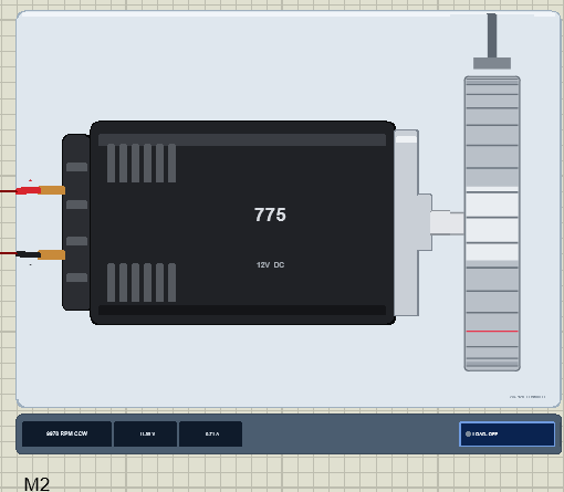
If a motor is held for half a second at more than 5 A, it writes STALLED to the simulation log; above 15 V it warns about the over-voltage, because this 775 is a 12 V motor.
The Demo Circuit
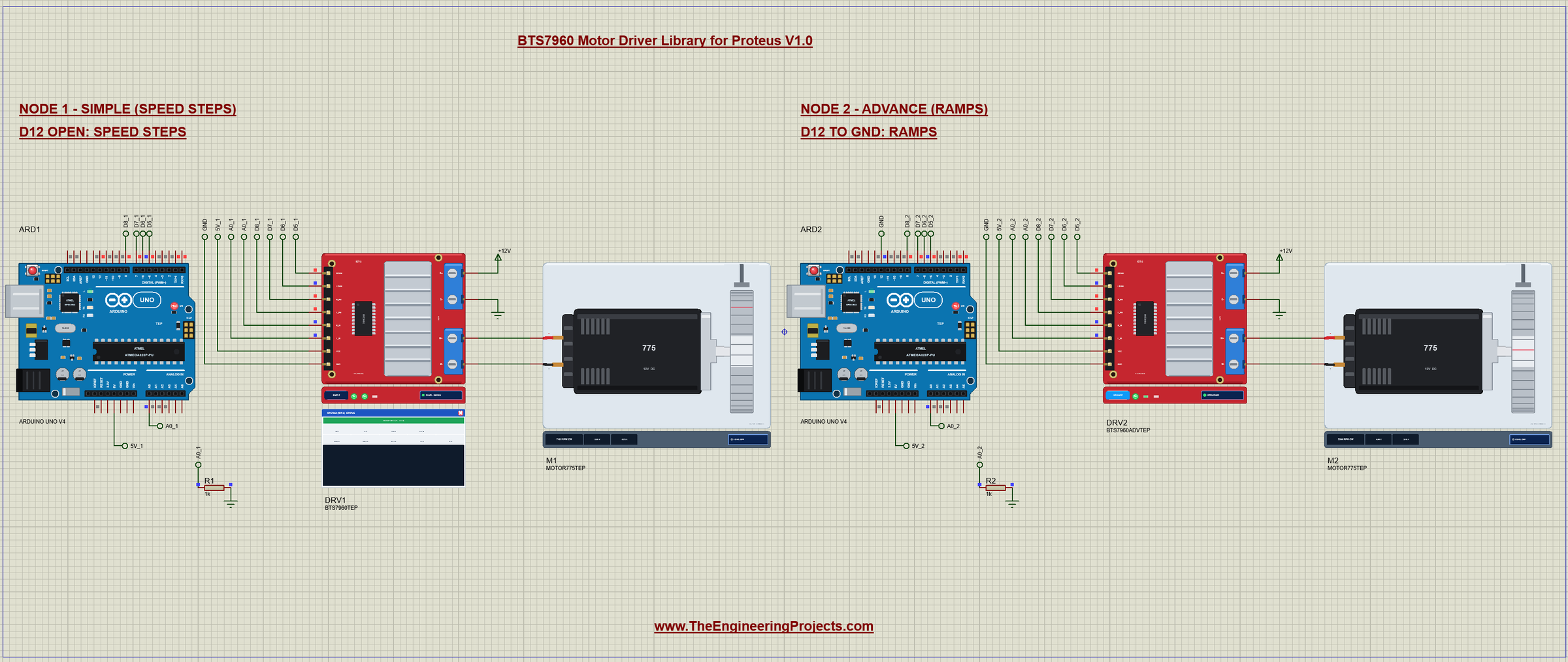
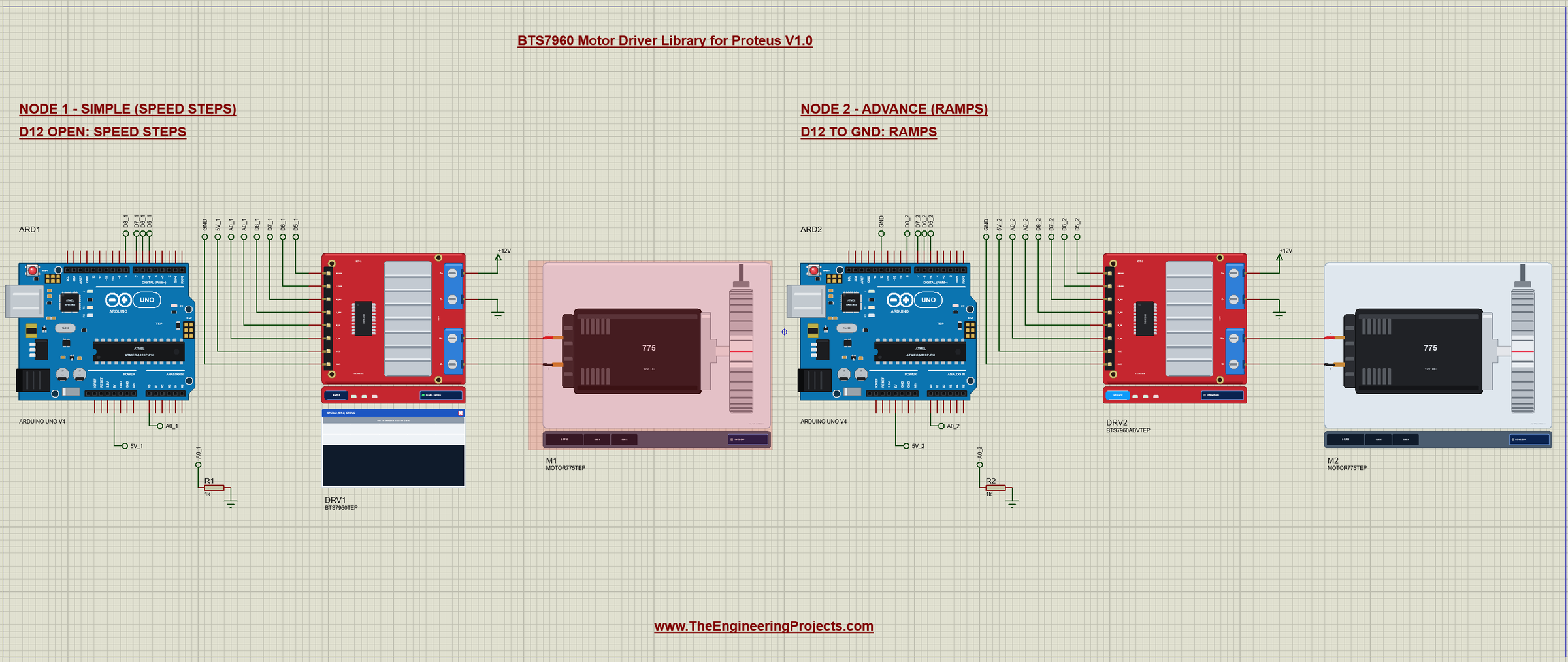
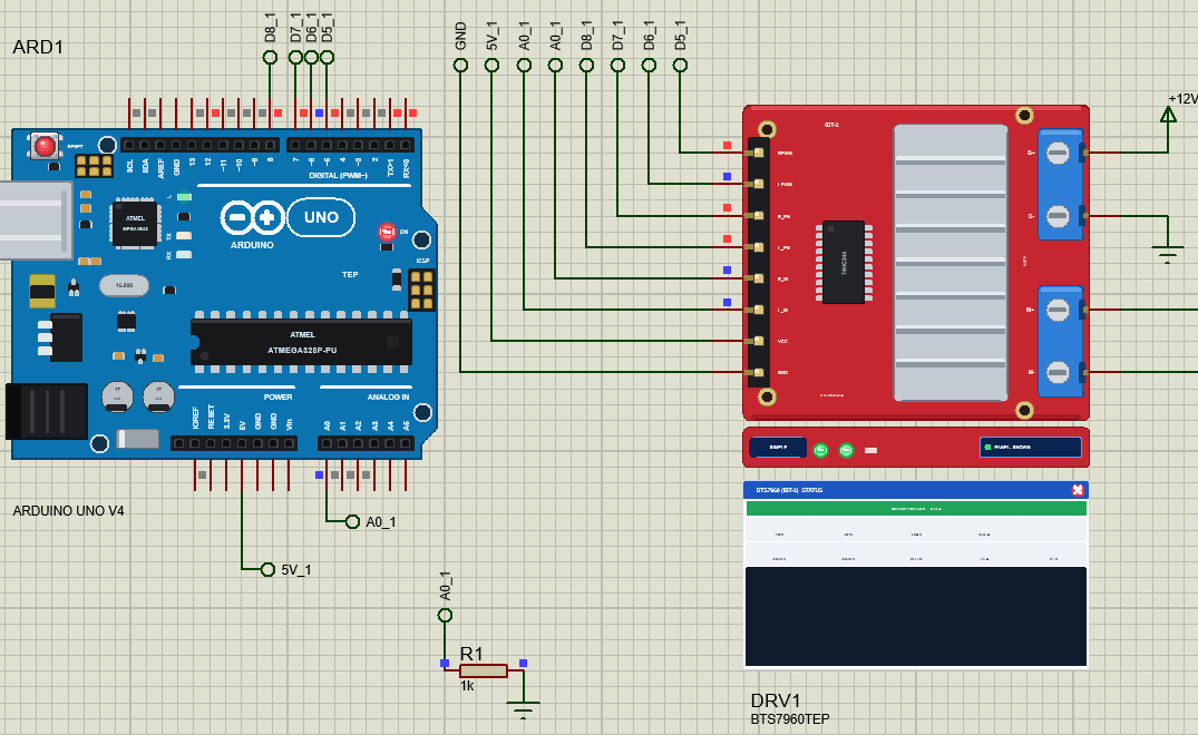
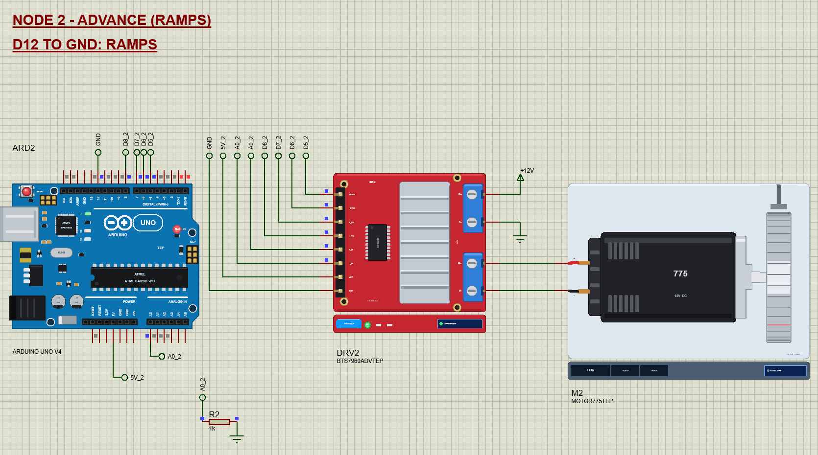
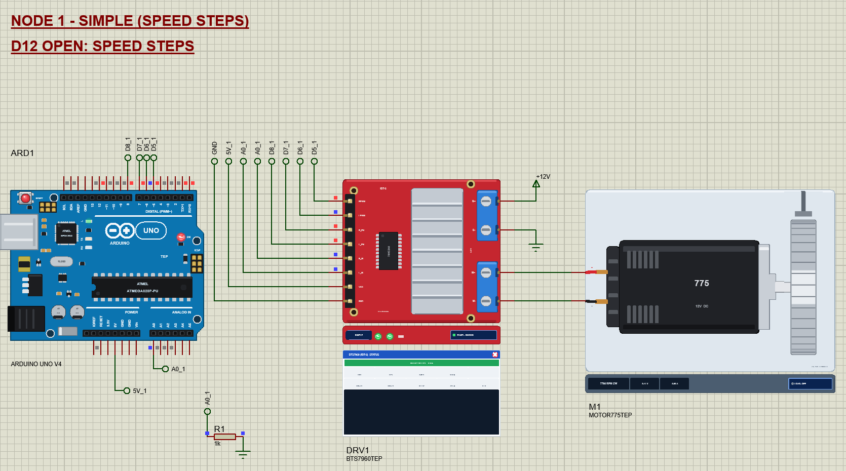
The demo project has two nodes. Each one is an Arduino UNO V4.0 from our Arduino UNO Library for Proteus V4.0, one IBT-2 driver, one 775 motor and a 1 kohm resistor for the current sense. Both UNOs run the same BTS7960_Demo.hex; the D12 pin chooses the demo. Node 1 leaves D12 open and runs hard speed steps on the Simple driver; node 2 ties D12 to GND and drives its Advance driver with soft ramps. B+ of both drivers comes from a +12V power terminal, which Proteus turns into a 12 V supply.
Wiring
| Module | Arduino UNO | Note |
|---|---|---|
| RPWM | D5 | PWM 980 Hz, forward |
| LPWM | D6 | PWM 980 Hz, reverse |
| R_EN | D7 | HIGH = the M+ half-bridge runs |
| L_EN | D8 | HIGH = the M- half-bridge runs |
| R_IS, L_IS | A0 | both on one pin, 1 kohm from A0 to GND |
| VCC | 5V | the logic |
| GND | GND | common with B- |
| B+, B- | supply | 6 - 27 V (12 V in the demo) |
| M+, M- | motor | M+ to the motor's +, M- to its - |
In Proteus every header pin reaches its UNO through a wire with a net label: D5_1, D6_1, D7_1, D8_1, A0_1 and 5V_1 for node 1, the same with _2 for node 2, and GND. R_IS and L_IS both carry the label A0_1, and the resistor R1 below the UNO connects A0_1 to GND. The motor is wired straight to M+ and M-. The serial monitor needs no wires at all, because it is built into the UNO V4.0.
Node 1: Speed Steps on the Simple Driver
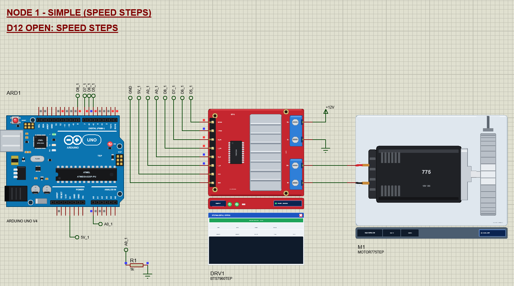
The speed steps run the motor forward at 25, 50, 75 and 100 %, brake, run it in reverse at 50 and 100 %, and let it coast. Each step lasts 2.5 s (the brake 1.5 s, the coast 3 s), and the list starts again. The steps are hard on purpose: every jump in speed is a jump in current, and the brake from full speed drew 28.6 A for a moment in the run.
Node 2: Ramps on the Advance Driver
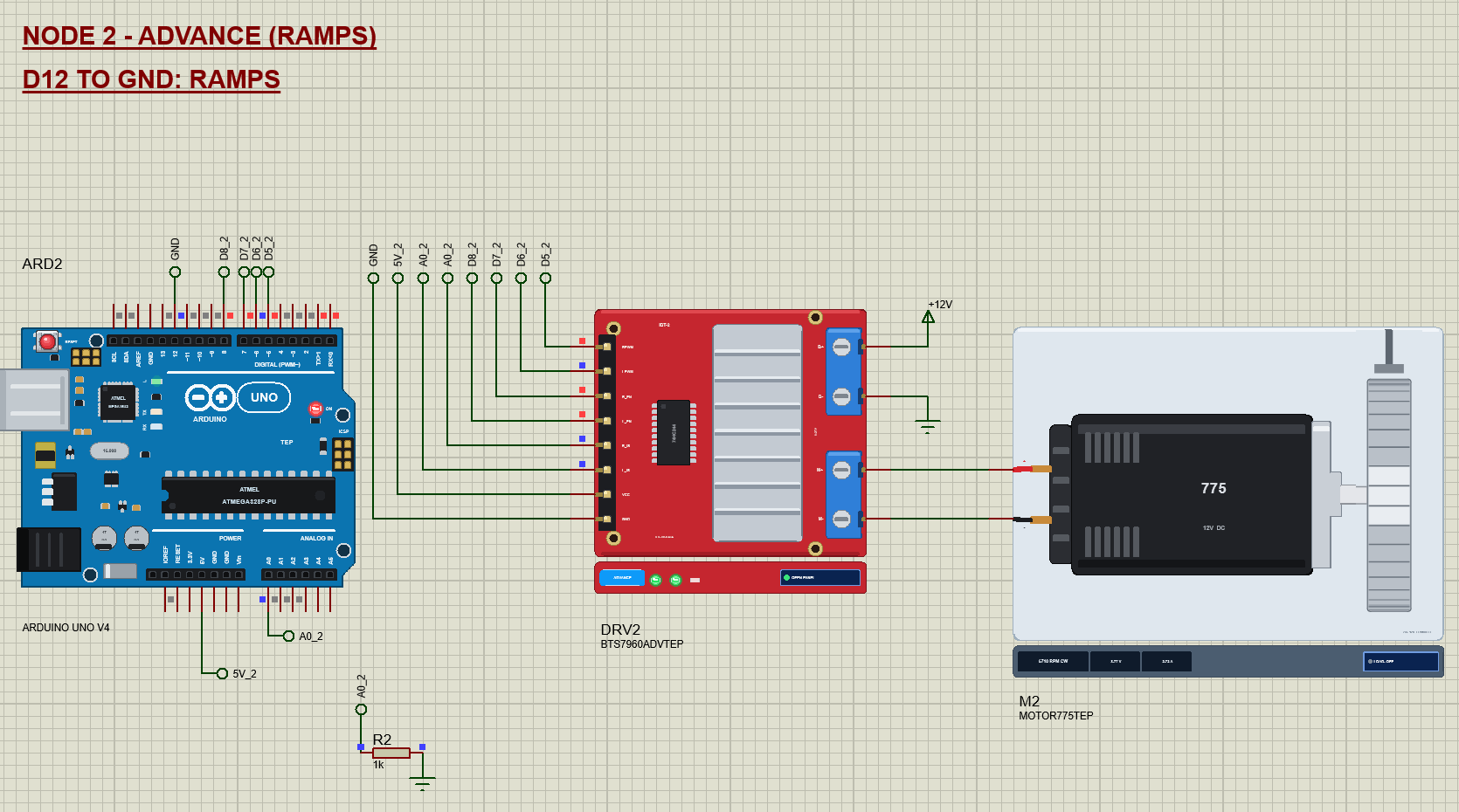
The ramps do the same work gently: a soft start to forward 100 % over 3 s, a hold, a ramp down to a stop, a short brake, the same in reverse, and a coast. Compare the peaks: the whole ramp cycle never drew more than 2.9 A, against 28.6 A for the hard steps of node 1. That is why real motor controllers ramp.
The Arduino Code
The demo needs no library: analogWrite() and digitalWrite() are all an IBT-2 needs. New to Arduino? Start with Arduino Tutorial for Beginners and Introduction to Arduino UNO. The pins come first:
const uint8_t RPWM = 5, LPWM = 6;      // the speed and direction
const uint8_t R_EN = 7, L_EN = 8;      // the enables (HIGH = run)
const uint8_t IS_PIN = A0;             // R_IS + L_IS, 1 kohm to GND
const uint8_t MODE_PIN = 12;           // open = speed steps, GND = ramps
One function turns a signed speed into the four inputs. It wakes both half-bridges, then puts PWM on RPWM for forward or on LPWM for reverse. The pin that must be LOW is written first, so the bridge never sees both directions for a moment. Zero writes both inputs LOW, which brakes:
void drive(int s) {                    // + forward, - reverse, 0 = brake
  speed = constrain(s, -255, 255);
  coasting = false;
  digitalWrite(R_EN, HIGH); digitalWrite(L_EN, HIGH);
  if (speed > 0) { analogWrite(LPWM, 0); analogWrite(RPWM, speed); }       // the pin that must be LOW first
  else if (speed < 0) { analogWrite(RPWM, 0); analogWrite(LPWM, -speed); }
  else { analogWrite(RPWM, 0); analogWrite(LPWM, 0); }                     // both LOW: brake
}
Coasting is different from braking: both enables go LOW, the half-bridges sleep and the motor rolls out on its own:
void coast() {                         // both half-bridges asleep: the outputs open, the motor rolls out
  analogWrite(RPWM, 0); analogWrite(LPWM, 0);
  digitalWrite(R_EN, LOW); digitalWrite(L_EN, LOW);
  speed = 0; coasting = true;
}
Reading the current sense is one line. The 1 kohm resistor turns 8.5 A into 1 V, so the ADC value times 5 / 1023 gives volts and times 8.5 gives amps:
float isAmps() { return analogRead(IS_PIN) * (5.0 / 1023.0) * 8.5; }Every 2 ms the sketch samples IS and keeps the sum and the peak of the current step, so it can print an average and a peak when the step ends:
void senseSample() {
  if (millis() - isAt < 2) return;
  isAt = millis();
  const float a = isAmps();
  isSum += a; isCount++;
  if (a > isPeak) isPeak = a;
}
The two demos are tables of steps. Each step holds the speed it ends at, how long it lasts, whether it ramps there and its name; the special value 999 coasts:
const int COAST_STEP = 999;
struct Step { int s; uint16_t ms; bool ramp; const char* name; };
const Step RAMPS[] = {{255, 3000, true, R0}, {255, 2000, false, R1}, {0, 2000, true, R2}, {0, 1000, false, R3},
{-255, 3000, true, R4}, {-255, 2000, false, R5}, {0, 2000, true, R6}, {COAST_STEP, 3000, false, R7}};A ramp sets a new speed every 20 ms, a straight line from where the step started to where it ends. The cast to a signed long matters: millis() is unsigned, and without it a ramp down would turn into a huge positive number and slam the motor into full reverse. We hit exactly that bug while testing, and the driver flagged a 56 A current limit:
  if (s.ramp && t < s.ms) {                // a ramp: a new speed every 20 ms
    static unsigned long rampAt = 0;
    if (millis() - rampAt >= 20) { rampAt = millis(); drive(rampFrom + (long)(s.s - rampFrom) * (long)t / (long)s.ms); }   // signed: a ramp may go down
  }
In setup() the pins become outputs, the motor starts coasting, and D12 decides the demo:
void setup() {
  pinMode(RPWM, OUTPUT); pinMode(LPWM, OUTPUT); pinMode(R_EN, OUTPUT); pinMode(L_EN, OUTPUT);
  coast();
  pinMode(MODE_PIN, INPUT_PULLUP);
  ramps = digitalRead(MODE_PIN) == LOW;
The commands from the serial monitor are read in loop(). "S" with a number sets the speed and stops the automatic demo:
  if (c[0] == 'S' && (c[1] == ' ' || c[1] == '=')) {
    autoRun = false; drive(atoi(c + 2));
    Serial.print(F("SET: ")); printSpeed(speed); Serial.println();
The HEX file is in the package. To change the sketch, open it in the Arduino IDE and export the compiled binary, as in How to get the HEX file from Arduino. It needs 7,940 bytes of flash and 406 bytes of RAM.
The Advance Pop-Up Window
At Run, the Advance driver opens TEP BTS7960 Motor Driver Advance, with the look of our TEP Serial Monitor Advance for Proteus. It has three tabs, Motor, Event log and Tests, plus Settings and Help behind the gear and question mark icons.
Motor and Current Sense
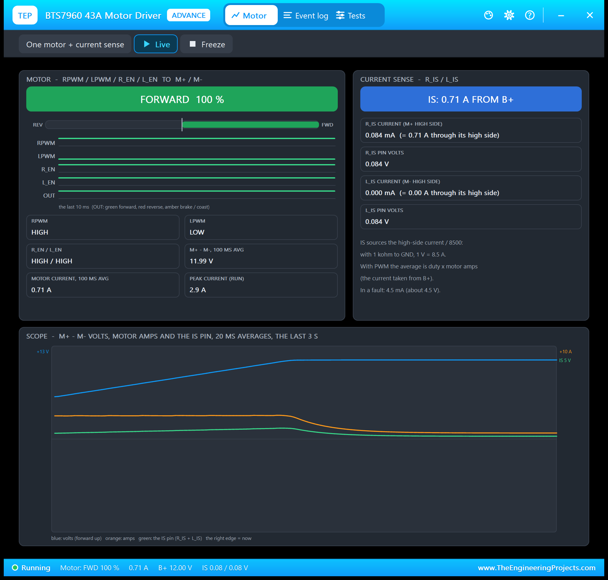
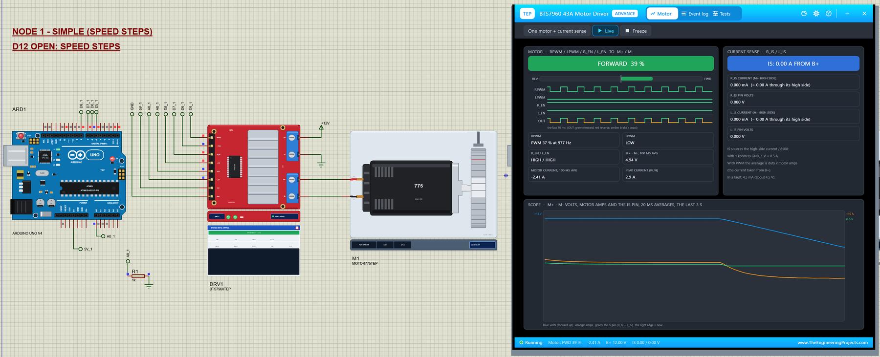
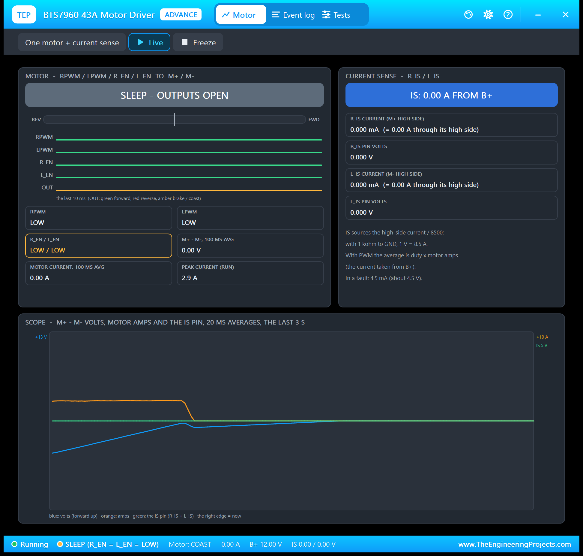
The left card belongs to the motor. The big coloured bar names the drive and its duty, the gauge runs from full reverse to full forward, and RPWM, LPWM, R_EN, L_EN and the output are drawn as waveforms over the last 10 ms. The tiles give the inputs, the volts across the motor and the motor current as 100 ms averages, and the peak current of the run. The right card is the current sense: the current each IS pin sources, the amps it stands for and the volts on the pin. The scope at the bottom draws the volts, the amps and the IS pin over the last 3 s. Freeze holds the page for a closer look.
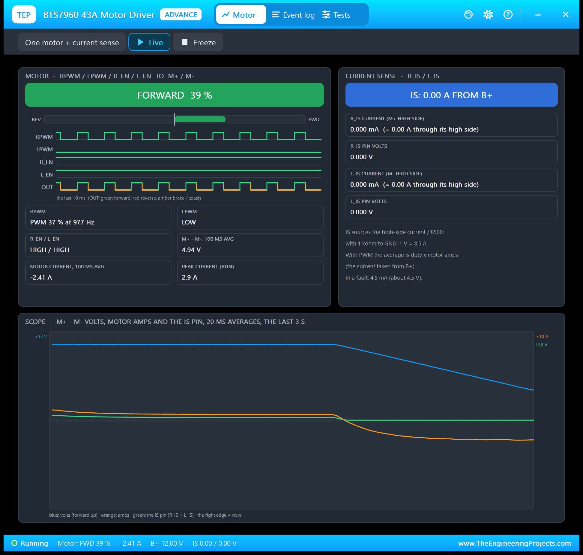
This screenshot shows the most surprising lesson of the BTS7960. While the motor slows down, its back-EMF is higher than the average voltage the driver gives it, so the current turns negative: the motor works as a generator. That current flows through the low-side switches, the high side carries nothing, and IS reads zero. A current sense on a BTS7960 measures the supply current, not the motor current.
Event Log
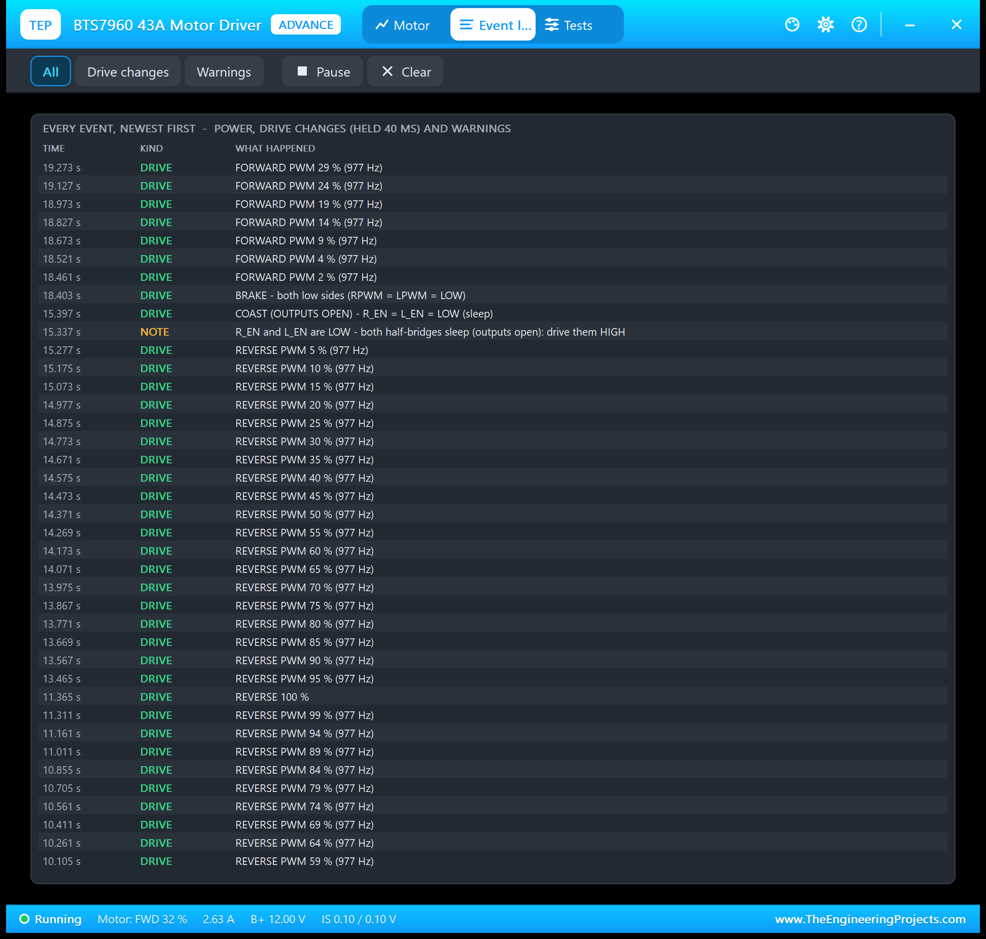
The Event log lists power on and off, every drive change that held for 40 ms, and the warnings. Each change says why it happened, for example "BRAKE - both low sides (RPWM = LPWM = LOW)" or "COAST (OUTPUTS OPEN) - R_EN = L_EN = LOW (sleep)", so a brake and a coast never look alike. During a ramp it logs a line for every 5 % of duty. Filter it by drive changes or warnings, pause it, or clear it.
The Test Tools
The Tests tab holds three tools. Each one reads the driver as the model sees it and gives every row a green, amber or red verdict.
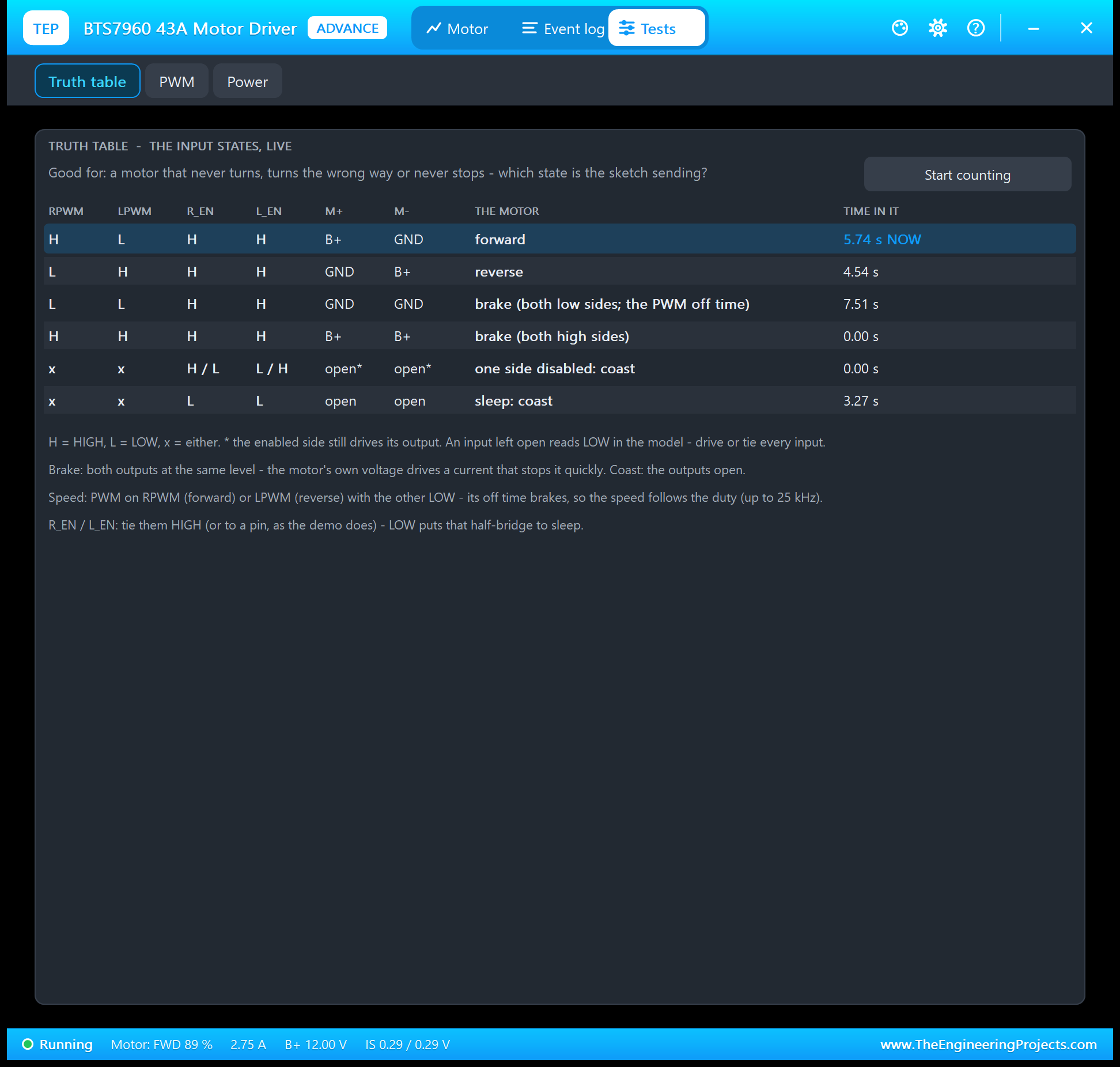
Truth table is good for a motor that never turns, turns the wrong way or never stops. It lists the six states of the IBT-2, forward, reverse, the brake on the low sides, the brake on the high sides, one side disabled and sleep, with M+, M- and what the motor does. It highlights the state the driver is in right now and counts the seconds it spent in each since Start counting.
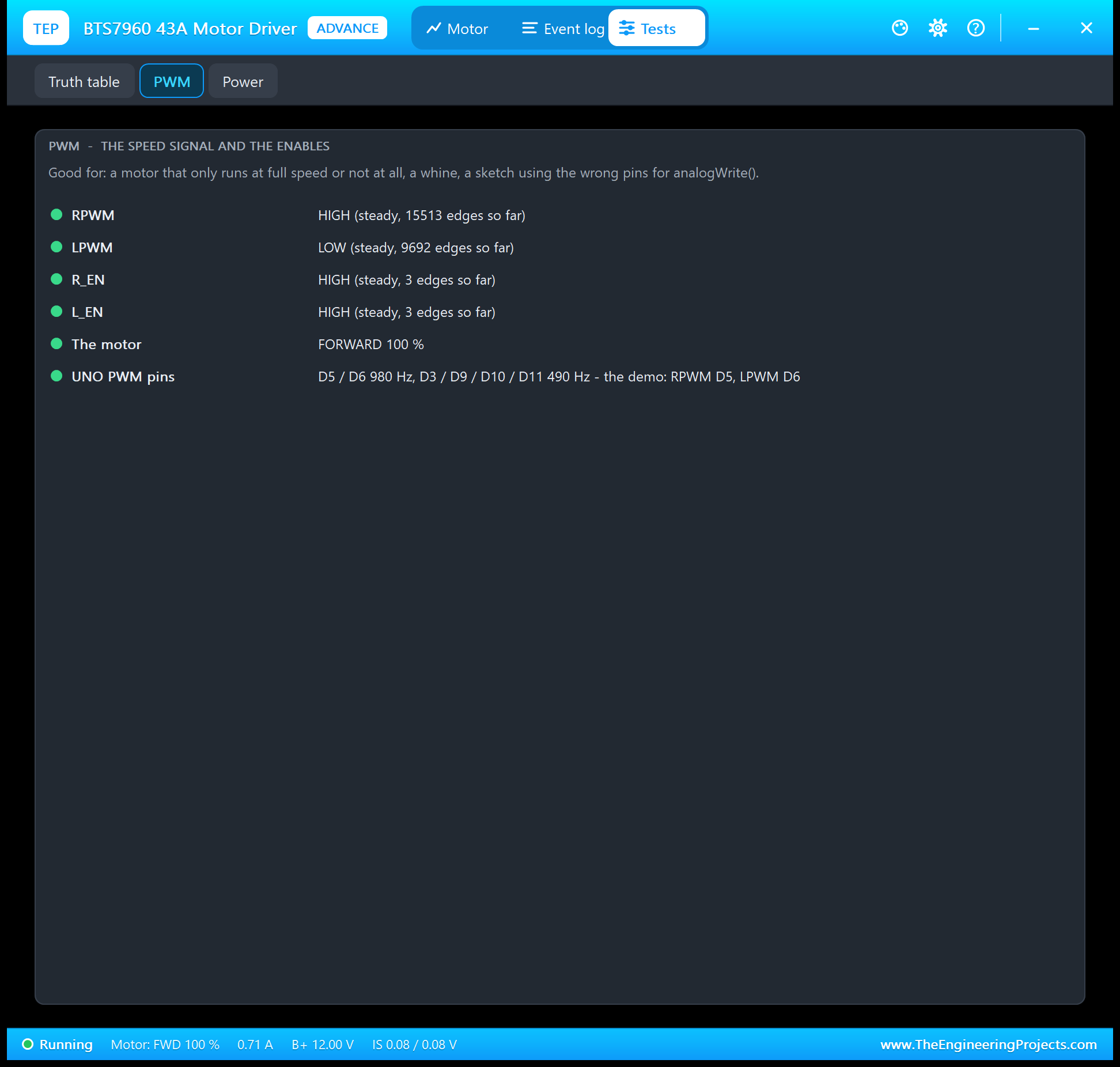
PWM is good for a motor that only runs at full speed or not at all, or a sketch that uses a pin without PWM. Every input shows its duty and frequency, or a steady HIGH or LOW with the number of edges so far. It also warns when PWM runs on both inputs at once, or on an enable, where the off time coasts instead of braking.
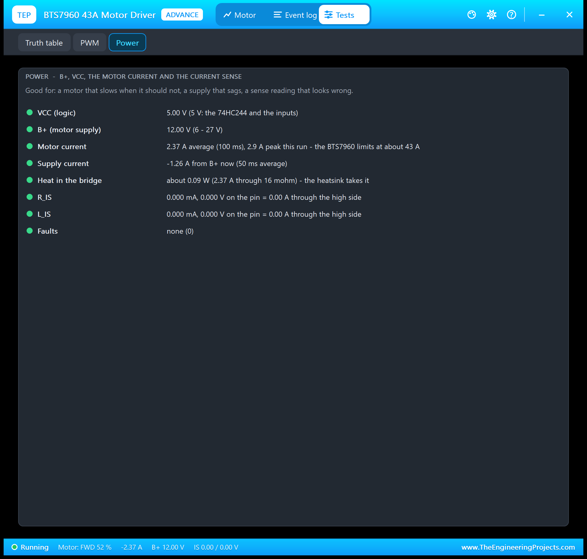
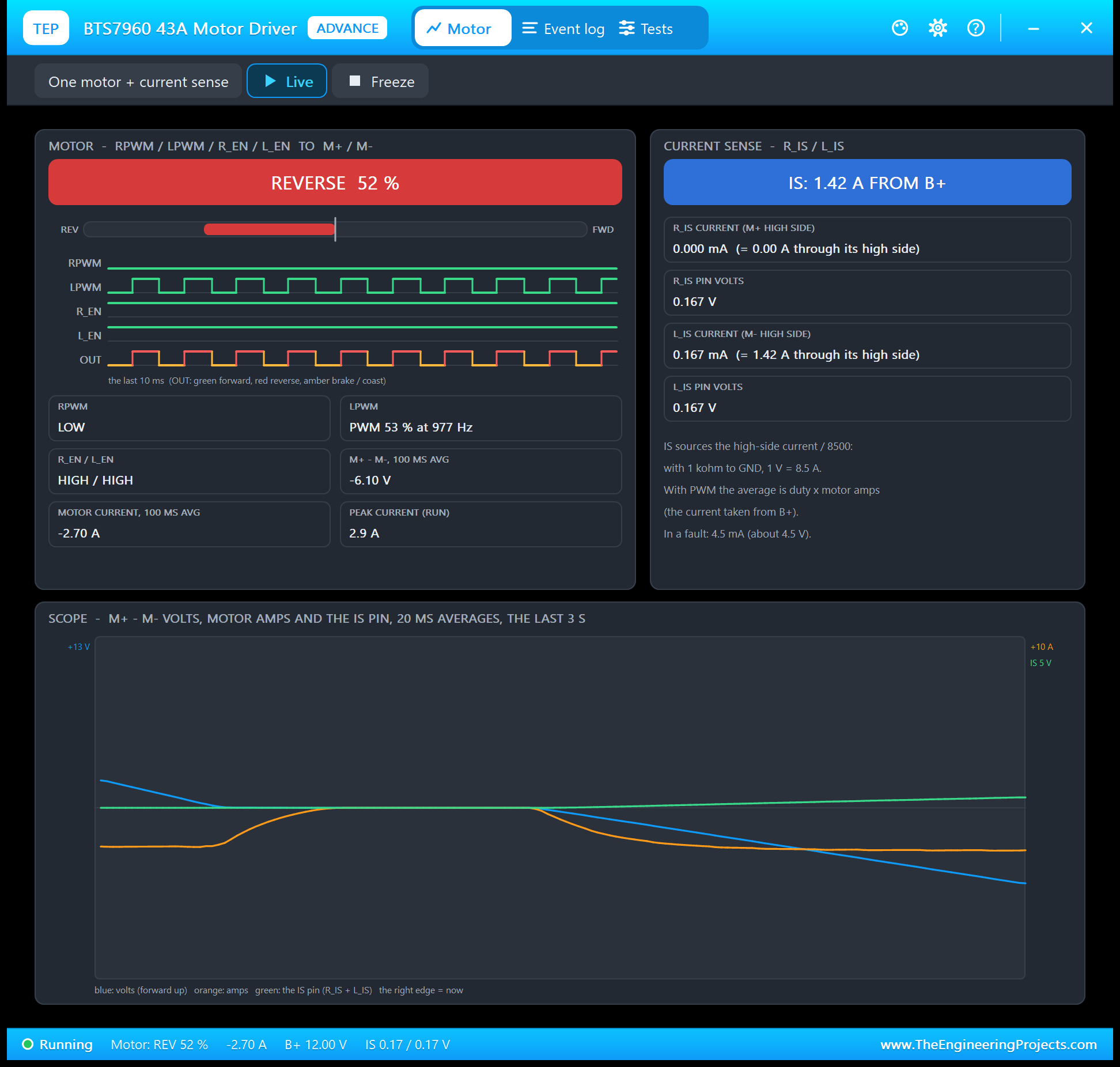
Power is good for a motor that slows when it should not, a supply that sags, or a sense reading that looks wrong. It shows VCC, B+ against the 6 - 27 V range, the motor current against the 43 A limit, the supply current, the heat in the bridge, both IS pins and the faults. In this screenshot the supply current is negative: the motor was ramping down and sending energy back to the supply.
The Serial Monitor
Both UNOs have the serial monitor built in, and it opens at Run. The screenshots use its Simple interface. Node 1 starts like this:
BTS7960 43A Motor Driver (IBT-2) demo - www.TheEngineeringProjects.com
Mode: SPEED STEPS (D12 open)
Commands: S <-255..255> | BRAKE | COAST | IS | RUN | HELP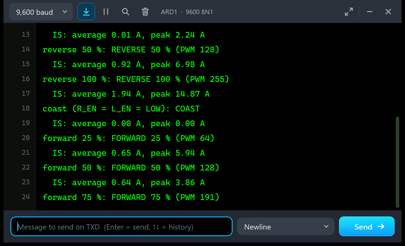
Every step prints what the motor gets, and when it ends, the average and the peak of the current sense during the step. Remember that IS reports the current from the supply, so a step that starts hard shows a high peak:
reverse 50 %: REVERSE 50 % (PWM 128)
  IS: average 0.92 A, peak 6.98 A
reverse 100 %: REVERSE 100 % (PWM 255)
  IS: average 1.94 A, peak 14.87 A
coast (R_EN = L_EN = LOW): COAST
  IS: average 0.00 A, peak 0.00 A
forward 25 %: FORWARD 25 % (PWM 64)
  IS: average 0.65 A, peak 5.94 A
forward 50 %: FORWARD 50 % (PWM 128)
  IS: average 0.64 A, peak 3.86 A
Look at forward 25 %: it starts while the motor still rolls backwards from the reverse step, so the current is high until the motor has turned around - a 5.94 A peak on the supply for a 25 % step. Node 2 runs the ramps:
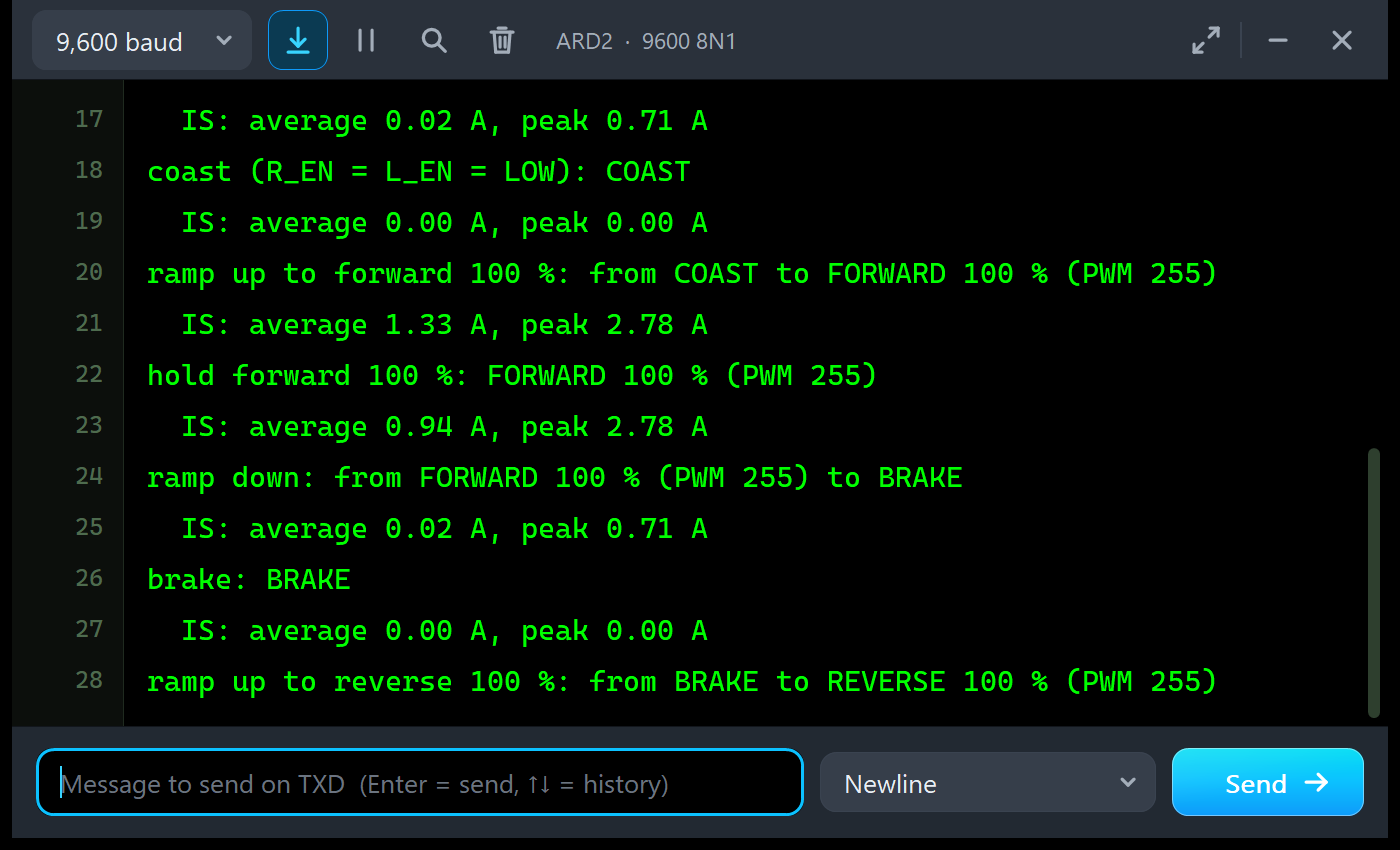
coast (R_EN = L_EN = LOW): COAST
  IS: average 0.00 A, peak 0.00 A
ramp up to forward 100 %: from COAST to FORWARD 100 % (PWM 255)
  IS: average 1.33 A, peak 2.78 A
hold forward 100 %: FORWARD 100 % (PWM 255)
  IS: average 0.94 A, peak 2.78 A
ramp down: from FORWARD 100 % (PWM 255) to BRAKE
  IS: average 0.02 A, peak 0.71 A
brake: BRAKE
  IS: average 0.00 A, peak 0.00 A
A ramp never draws more than 2.78 A from the supply here. And during the ramp down the average is almost zero, because the motor gives energy back instead of taking it.
Commands
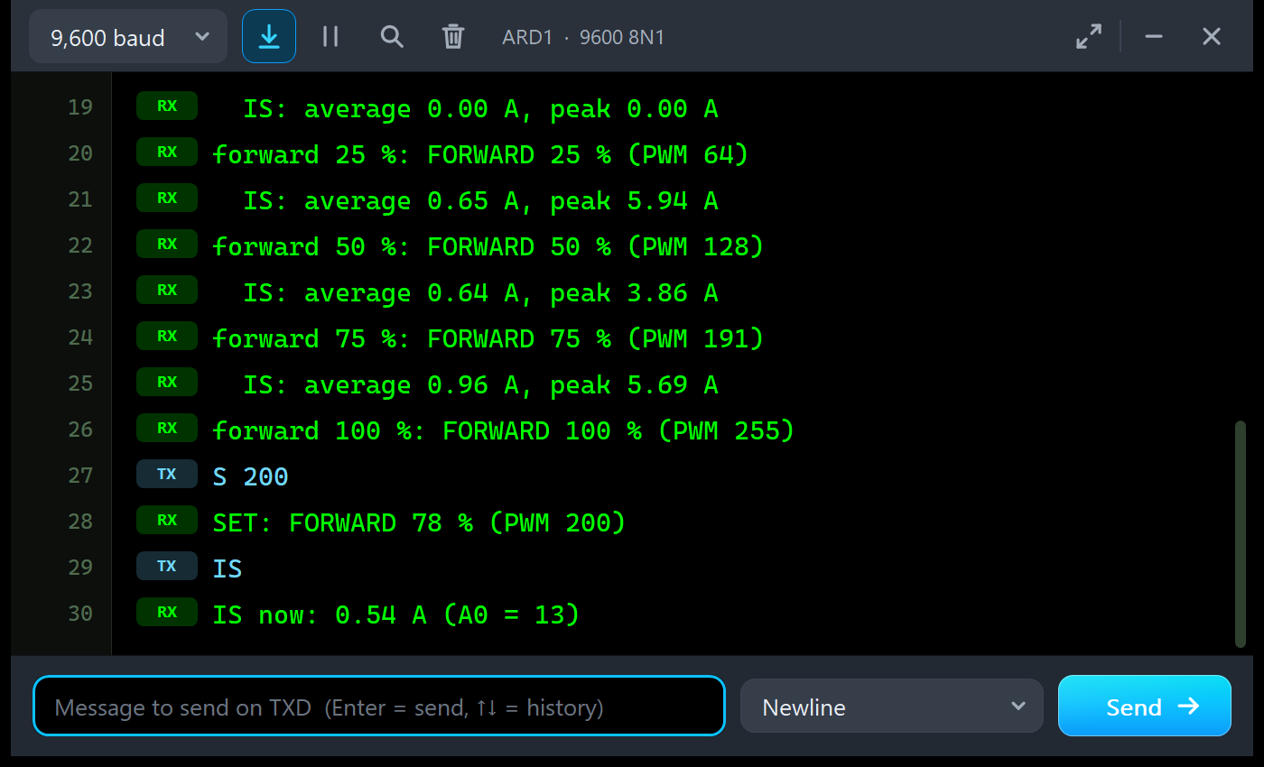
Type a command in the monitor and press Enter. S 150 or S -200 sets the speed, S 0 or BRAKE brakes, COAST puts both half-bridges to sleep, IS prints the current sense reading, RUN starts the demo again and HELP lists them. In the run:
S 200
SET: FORWARD 78 % (PWM 200)
IS
IS now: 0.54 A (A0 = 13)
The A0 value 13 means 0.064 V, which is 0.54 A: PWM 200 is a duty of 78.5 %, and 78.5 % of the motor's 0.69 A is exactly that.
The Simulation Log
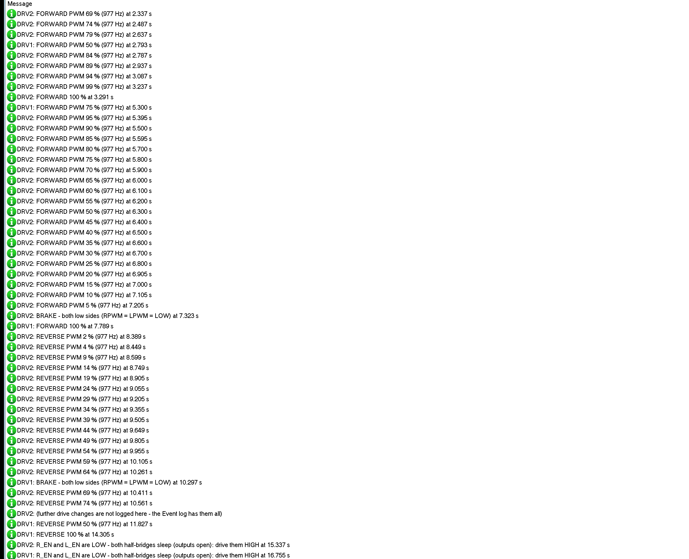
Each driver writes its power-up and every drive change to the simulation log, so a long run leaves a readable story of what the motor did. The power line shows the supplies, for example "POWER ON - VCC 5.00 V, B+ 12.00 V". After 60 drive changes the log stops and points to the Event log, which keeps them all.
How the Simulation Handles PWM
Proteus solves the analog part of a circuit in time steps, here at most 2 ms long, and it solves each step before it runs the digital part up to that time. So the driver learns about a PWM edge only after the step that contains it. While PWM runs, the model therefore drives each step with the duty measured over whole PWM periods, the same every step. That matters with a motor of only 0.4 ohm: a step's own share of the pulses (a 2 ms step holds 1.96 periods at 980 Hz) would make the current jump by half an amp from step to step. On a PC we checked that the speeds stay within 0.2 % of the speed the average voltage gives, and that IS equals the duty times the motor current.
One consequence: the volts, amps and IS readings are averages, not single PWM pulses. A real motor smooths the pulses with its inductance, so the average is what its speed and your Arduino's readings follow.
Troubleshooting
- The motor never turns and the PWR LED is dark: no supply on B+ and B- (NO MOTOR SUPPLY in the banner; B+ needs 6 - 27 V), or no VCC.
- The PWR LED is lit but nothing turns: R_EN and L_EN are LOW or open (SLEEP), or both inputs are LOW (brake); check the Truth table tool.
- Full speed or nothing: the sketch uses a pin without PWM, or only writes 0 and 255; check the PWM tool.
- The motor turns the wrong way: swap its two wires, or swap RPWM and LPWM in the sketch.
- CURRENT LIMIT: a stalled or heavily loaded motor, or a reversal at full speed; ramp, brake first or use less PWM.
- IS reads zero: R_IS and L_IS are not connected, the resistor to GND is missing, or the motor is braking or slowing down (no high-side current).
- No part, no flywheel or no monitor: TEPBTS7960.DLL, TEPMOTOR775.DLL or TEPARDUINO.DLL is missing from MODELS and the project folder; a closed monitor opens again with a click on the UNO's USB port.
Things to Know Before Using a Real IBT-2
- The supply: a 775 draws about 30 A for a moment when it starts at full voltage, and more when it is reversed at full speed. Use a supply that can deliver it, thick wires on B+, B-, M+ and M-, and a common GND with the Arduino.
- The IS pins: measure the voltage on them before you connect them to an Arduino; in a fault the BTS7960 drives IS up to several volts. Use a 1 kohm resistor (or smaller) to GND.
- Ramps: ramp the speed up and down, and brake before you reverse a fast motor; the demo's ramps keep the current near the running current.
- Heat: the heatsink is there for a reason; keep air around it at high currents.
- PWM pins: D5 and D6 give 980 Hz, D3, D9, D10 and D11 give 490 Hz; the BTS7960 accepts up to 25 kHz.
Limitations of the Simulation
- The outputs follow PWM one SPICE step (up to 2 ms) late with the duty over whole periods and show averages; single pulses are not resolved.
- The current limit itself is not simulated: above 43 A the model logs CURRENT LIMIT and IS gives the fault current, but the current is not cut as on a real chip.
- Not modelled: the slew-rate resistors, dead time, the chips' heating and thermal shutdown, the 74HC244's timing, the motor's inductance and current ripple, and damage from over-voltage or over-current (the model warns).
- The strip, its LEDs, the panels and the LOAD button are TEP additions.
- The models are our own, written from Infineon's BTS7960 datasheet, the IBT-2 module's documentation and typical data of 12 V 775 motors; this library is not made or endorsed by Infineon, the makers of the IBT-2 module or Labcenter.
- Licences: the demo needs no library; the HEX file contains the Arduino AVR core 1.8.6 with LGPL-licensed code, and the sketch is included.
- Tested in Proteus 8.5 in October 2026 (the demo as shipped on two Arduino UNO V4.0 boards with their built-in monitors: the speed steps, the ramps, the LOAD button, the commands, the pop-up and the three tools; about 0.47 x real time with the pop-up and both monitors open). Proteus 7 is not supported.
So, that was all about the BTS7960 Motor Driver Library for Proteus V1.0. I hope the truth table, the enables, the current sense and the difference between hard steps and soft ramps are clear now, so your big motor runs cool and safe from its first run. If you use the BTS7960 Motor Driver Library for Proteus in a project, please share it in the comments or in our forum, and if you have any questions, ask in the comments and I will help you out. Till the next tutorial, take care and have fun!
Comments
0