


OLED SH1106 Library for Proteus V1.0 (1.3 inch I2C + Arduino)


Hello friends, I hope you all are doing great. Today, I am going to share the new OLED SH1106 Library for Proteus V1.0. The 1.3" OLED is the big brother of the popular 0.96" display: the same 128 x 64 pixels on a bigger glass, easier to read from a distance, on a board with the same four I2C pins. But inside it hides a different controller, the SH1106, and that catches almost everybody once: an SSD1306 sketch shows only random dots on it. With this OLED SH1106 Library for Proteus, your sketch draws on a 1.3" OLED that behaves like the real one, including that trap.
This is our third OLED library, after the OLED SSD1306 Library for Proteus V1.0 and the OLED 128x32 Library for Proteus V1.0, and it runs on the same own OLED model, now with an SH1106 controller written from its datasheet: the 132-column RAM, the column offset of the 1.3" glass and the commands it does not have. You get four devices: a white and a blue OLED, each as OLED SH1106 Simple, with a live STATUS panel on the schematic, and OLED SH1106 Advance, with a pop-up window, a bus log and four OLED test tools. The demo runs on our Arduino UNO V4.0, with its serial monitor built into the board.
NOTICE: This library is very special to our team. A 1.3" OLED looks like a bigger copy of the 0.96", but its SH1106 controller has more RAM than the glass, no addressing modes and no scrolling, and even the power pins of the board are the other way round. We modelled all of that from the datasheet, tested it with the real Adafruit libraries bit by bit, and made the model tell you what went wrong: the wrong library, a missing column offset, a reversed supply. It took our team a lot of hard work and many test runs. Your feedback is the fuel that keeps us going, so please tell us what you think in the comments below or in the OLED Library board of our forum. And if our free libraries help you, you can buy us a coffee. So, let's get started with the OLED SH1106 Library for Proteus V1.0:
What is a 1.3" OLED SH1106 Display?
A 1.3" OLED SH1106 display is a graphic display module: a 1.3" glass with 128 x 64 pixels and the SH1106 controller behind it, on a blue board of about 35 x 33 mm with a 4-pin I2C header on top. OLED means organic LED: every pixel makes its own light, so there is no backlight, black is really black, and the text stays sharp from any angle. The glass is one colour, most often white or blue.
The SH1106 only knows pixels, like the SSD1306: your Arduino library draws letters, lines and pictures into a picture in memory and sends it to the display. For the SH1106, that is the job of the Adafruit SH110X library (its class Adafruit_SH1106G) together with the Adafruit GFX library. U8g2 has an SH1106 driver too. The drawing commands are the same as for our 0.96" OLED; only the display object and the colour name change.
The 1.3" OLED at a Glance
| Feature | Value |
|---|---|
| Display | 1.3", 128 x 64 pixels, one colour (white or blue) |
| Controller | SH1106, display RAM of 132 x 64 pixels; the glass shows the columns 2 to 129 |
| Board | About 35.4 x 33.5 mm, four mounting holes, the 4-pin header on top |
| Pins | VDD, GND, SCK, SDA (the supply pins the other way round from the 0.96" board) |
| Address | 0x3C (most modules) or 0x3D, set by a resistor on the back (marked 0x78 / 0x7A) |
| Supply | 3.3 V or 5 V on VDD (the module has its own regulator) |
| I2C speed | Up to 400 kHz; a full picture is 1024 bytes in 8 page writes, about 39 ms at 400 kHz |
| Arduino libraries | Adafruit SH110X + Adafruit GFX: Adafruit_SH1106G display(128, 64, &Wire, -1) |
Terms You Will See in This Article
| Term | Meaning |
|---|---|
| I2C | A two-wire bus: SDA carries the data, SCK (SCL) the clock; each device has its own address |
| Page | A band of 8 pixel rows; one byte of a page is 8 pixels on top of each other |
| Column offset | The RAM column where the glass starts: 2 on the 1.3" module |
| Page addressing | The only way the SH1106 takes data: choose a page and a column, then send bytes |
| DC-DC | The SH1106's converter for the panel voltage, on after reset (AD 8B) |
| Frame | One whole picture: the 8 pages that one display() of the library sends |
How the SH1106 Differs from the SSD1306
On the outside, the two controllers look alike: the same control byte (0x00 for commands, 0x40 for data), the same contrast, inverse and display on / off commands, the same pages of 8 rows. The differences are where a sketch breaks:
| SSD1306 (0.96" / 0.91") | SH1106 (1.3") | |
|---|---|---|
| Display RAM | 128 x 64 | 132 x 64; the glass shows the columns 2 - 129 |
| Addressing | Page, horizontal or vertical, with column / page windows (20, 21, 22) | Page addressing only |
| A whole frame | One long write: the address moves on by itself | Eight page writes: page, column, 128 bytes |
| Panel voltage | Charge pump, must be switched on (8D 14) | DC-DC, on after reset (AD 8B) |
| Scrolling | Built in (26 - 2F) | None: the sketch moves the picture itself |
| Board pins | GND, VCC, SCL, SDA | VDD, GND, SCK, SDA |
The column offset is the first catch. The SH1106 has 132 columns of RAM, but the 1.3" glass has 128 pixels, wired to the 128 columns in the middle: 2 to 129. A driver made for the SH1106 writes every page from column 2. A driver that writes from column 0 puts the picture 2 pixels too far left, and the 2 columns on the right are never written.
The missing commands are the second catch. An SSD1306 library sends commands the SH1106 does not have, and the chip simply skips them. Their parameter bytes then arrive as commands of their own, and some of them mean something to the SH1106. We will see the result below, because our model does exactly that.
What's New in OLED SH1106 Library for Proteus V1.0
Here is what the first version brings:
- The 1.3" SH1106 module on our own model in
TEPOLED.DLL: the 132 x 64 RAM, page addressing, the column offset of the glass and the SH1106's own commands. - The SSD1306 trap made visible: an SSD1306 library shows random dots, as on a real module, and the panel and the Init check name the commands it sent.
- Two more warnings: PICTURE 2 PIXELS LEFT for a driver without the column offset, and SUPPLY REVERSED for VDD and GND swapped.
- A real 1.3" module on the schematic: the blue board drawn at twice the real size, with its four holes, the header on top and our LEDs, address selector and panel button.
- Four devices in
TEPOLEDSH1106.LIB: white and blue glass, each Simple and Advance. - Four OLED test tools on the Advance: Init check, I2C bus, Speed and Pixels, plus Freeze and a pixel grid on the big glass.
- A two-UNO demo on our Arduino UNO V4.0: the Adafruit SH110X library, a dashboard, a software marquee, an OFFSET command that shows the column offset, and more Serial commands.
- A compact package: about 1.31 MB, without the C++ source code.
The model file TEPOLED.DLL is shared with our 0.96" and 0.91" OLED libraries and runs their devices too; we re-ran both of their demos on it. If you have them, keep this newer DLL.
OLED SH1106 Simple vs OLED SH1106 Advance
All four devices share one model and the same module. They differ in the glass colour and in where you see the extras:
| Device | Name in Pick Devices | Glass | Extras |
|---|---|---|---|
| SH1106WHITETEP | OLED SH1106 128x64 V1.0 White - Simple | White | STATUS panel on the sheet |
| SH1106WHITEADVTEP | OLED SH1106 128x64 V1.0 White - Advance | White | Pop-up window and tools |
| SH1106BLUETEP | OLED SH1106 128x64 V1.0 Blue - Simple | Blue | STATUS panel on the sheet |
| SH1106BLUEADVTEP | OLED SH1106 128x64 V1.0 Blue - Advance | Blue | Pop-up window and tools |
Pick a Simple OLED when you want the controller's state and its warnings right on the schematic. Pick an Advance OLED when the schematic is crowded, or when you want the bus log, the tools and a big copy of the glass. The address selector works on all four.
Download OLED SH1106 Library for Proteus
Click the button below to download OLED-SH1106-Library-for-Proteus-v1.0.zip (about 1.31 MB, without the C++ source code):
OLED SH1106 Library for Proteus V1.0- README.txt: a detailed guide to the files, the wiring, the controller, the test tools and real hardware.
- Proteus Library Files:
TEPOLEDSH1106.LIB(all four devices) and our Arduino library V4.0,ArduinoV4TEP.LIB, with the Arduino UNO V4.0 of the demo. - Proteus Model Files:
TEPOLED.DLLandTEPARDUINO.DLL. - Proteus Simulation:
OLED-SH1106-ArduinoUnoV4.pdsprj,OLED_SH1106_Demo.hex(both UNOs run it) and copies of both DLLs. - Arduino Code:
OLED_SH1106_Demo.ino, the demo sketch. It needs the "Adafruit SH110X" library from the Library Manager, which offers Adafruit GFX and Adafruit BusIO too.
Want all three OLEDs? This OLED is also part of our OLED Library for Proteus V1.0: the 0.96" SSD1306, the 0.91" 128x32 and the 1.3" SH1106 in one library (14 parts, one DLL), with a demo in which one Arduino UNO drives all three.
The Arduino files are the ones of our Arduino Library for Proteus V4.0, so if you have it installed, they are the same. No Proteus yet? Read How to Download and Install Proteus 7 and 8. New to libraries? Follow How to Install a New Library in Proteus.
How to Install OLED SH1106 Library for Proteus
- Close Proteus and extract the whole zip file to a normal folder, for example your Desktop.
- Copy the two files from Proteus Library Files into the LIBRARY folder, usually
C:\Program Files (x86)\Labcenter Electronics\Proteus 8 Professional\LIBRARY(on some PCsC:\ProgramData\Labcenter Electronics\Proteus 8 Professional\LIBRARY; use the folder that already holds Proteus's own .LIB files). - Copy
TEPOLED.DLLandTEPARDUINO.DLLfrom Proteus Model Files into the MODELS folder. - Delete
TEPOLEDSH1106.IDXfrom the LIBRARY folder if there is one; Proteus makes a new index. - Start Proteus, press P and search for SH1106. You get the four devices.
Tip: the demo project needs the .hex file and the two DLLs beside it, so keep the Proteus Simulation folder together. The library was tested in Proteus 8.5; Proteus 7 is not supported.
The OLED SH1106 Board in Proteus
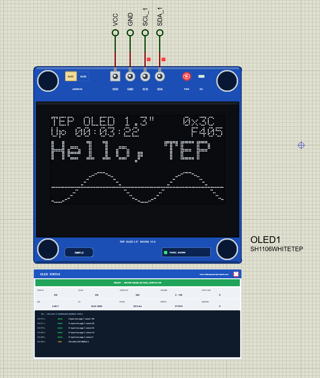
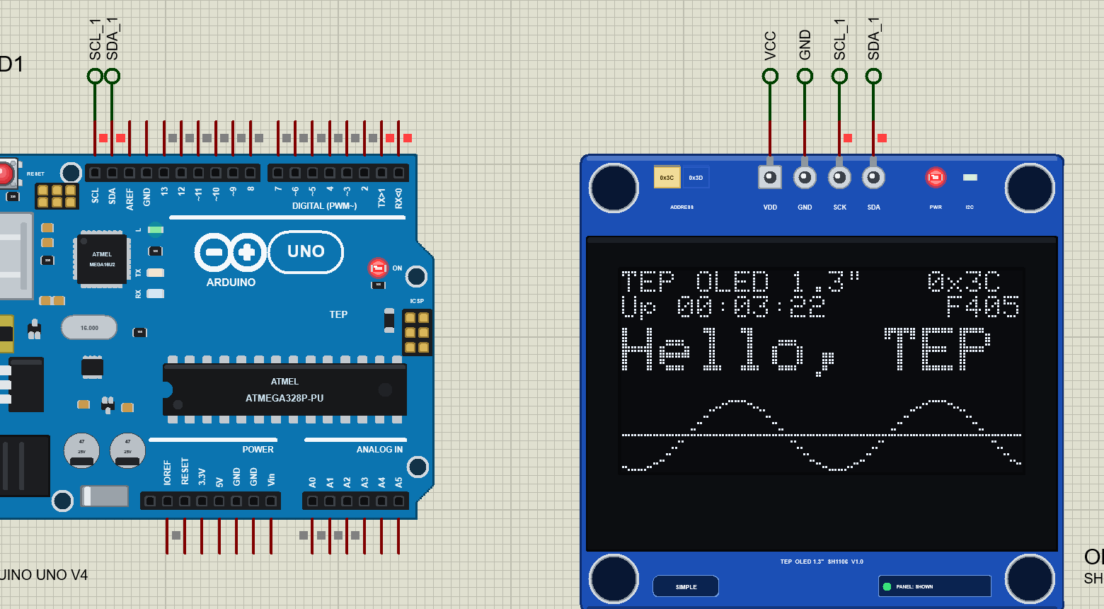
The part looks like the real module: the blue board with its four mounting holes, the glass taking most of it and the 4-pin header centred on the top edge, pins pointing up and printed VDD, GND, SCK, SDA. We drew it at twice the real size, so the 128 x 64 pixels stay readable on a schematic. Here is OLED1, the white Simple OLED, running the demo's dashboard:
Pinout
| Pin | Name | What it does | Demo connection |
|---|---|---|---|
| 1 | VDD | Supply, 3.3 V or 5 V | VCC (net label, the 5 V rail) |
| 2 | GND | Ground | GND (net label) |
| 3 | SCK | I2C clock (the SCL line) | The UNO's SCL pin, through the label SCL_1 |
| 4 | SDA | I2C data (open drain, with the module's pull-up) | The UNO's SDA pin, through the label SDA_1 |
The Board Up Close
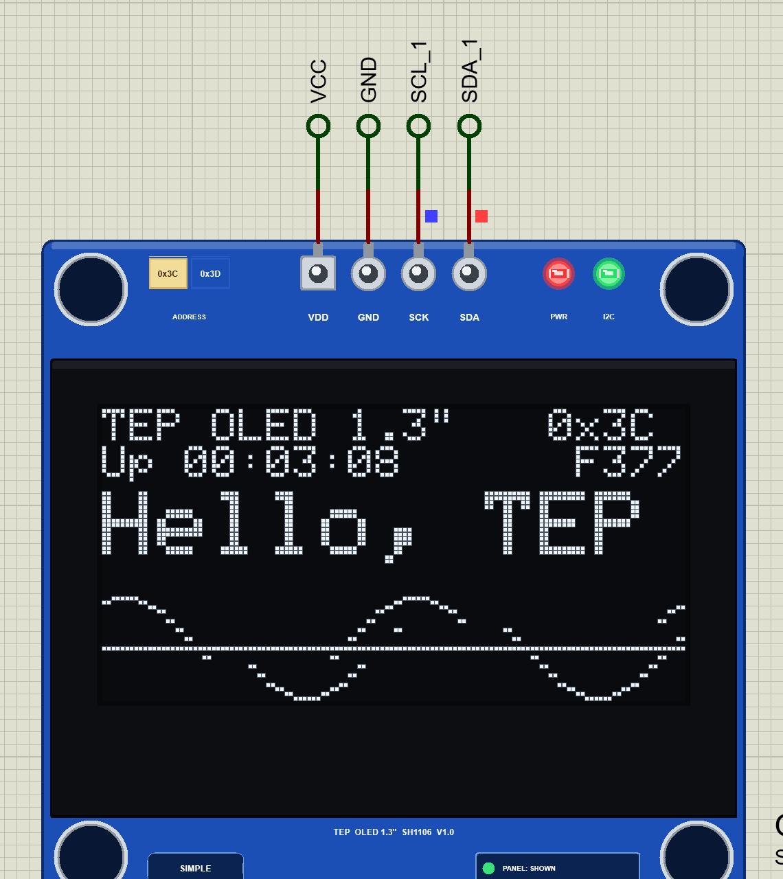
Everything on the board is drawn by the model and changes while the simulation runs. The pixels glow in the glass colour, at the brightness the contrast sets. The PWR LED is lit while the module has power, and the I2C LED flashes green whenever the Arduino talks to this address. A real module has no LEDs at all, so these are our additions to help you see what happens.
LEDs and Indicators
| Indicator | What it shows | On the real module? |
|---|---|---|
| The pixels | The RAM columns 2 - 129, at the contrast's brightness | Yes |
| PWR LED (red) | Lit while the module has power | TEP addition |
| I2C LED (green) | Flashes on every I2C transaction to this address | TEP addition |
| ADDRESS selector | 0x3C or 0x3D, clickable while the simulation runs | TEP addition (a resistor on the back) |
| SIMPLE / ADVANCE badge, PANEL / OPEN PANEL | Which device this is, and the panel button | TEP addition |
Component Properties
| Property | Meaning | Default |
|---|---|---|
| PANEL | Simple devices only: the STATUS panel at the start, OPEN or CLOSED | OPEN |
| ADDRESS | The I2C address, 0x3C or 0x3D; the selector follows it | 0x3C |
Every run starts from these properties; a click on the selector changes the address for that run only. In the demo, OLED2 has ADDRESS = 0x3D.
VDD GND SCK SDA: Watch the Pin Order
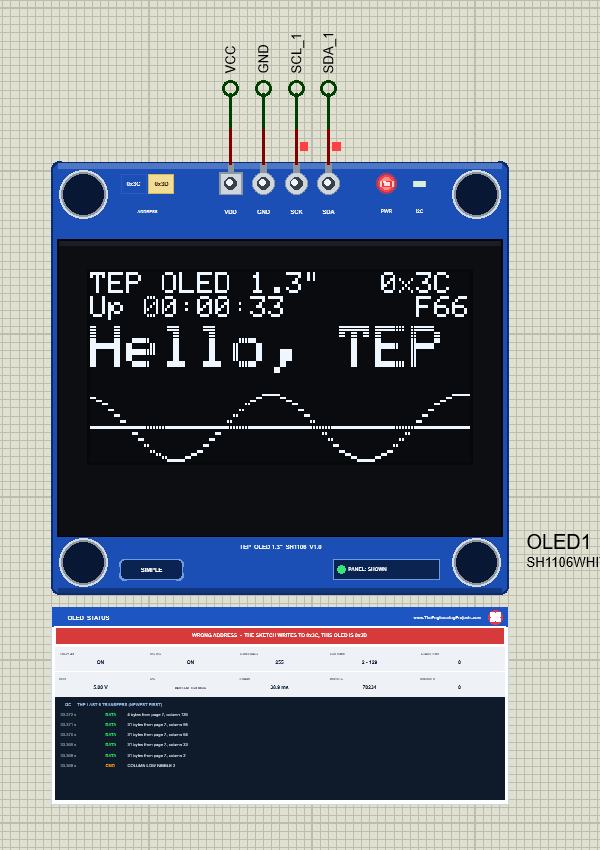
Put a 1.3" board next to a 0.96" board and the trap is plain to see: the 0.96" is printed GND, VCC, SCL, SDA, and most 1.3" boards are printed VDD, GND, SCK, SDA. The supply pins are swapped. Copy the wiring of a 0.96" project by position, and the module gets its supply the wrong way round, which can damage a real one. We wired OLED1 that way in a test copy of the demo:
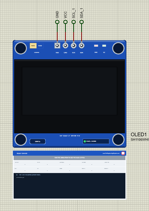
The simulation log gets a line too, and the sketch reports "No OLED found - check SDA (A4), SCK (A5), VDD", because a module without power does not answer. Some sellers print GND, VDD instead, so always read the pins of your own board.
The Address Selector: 0x3C or 0x3D
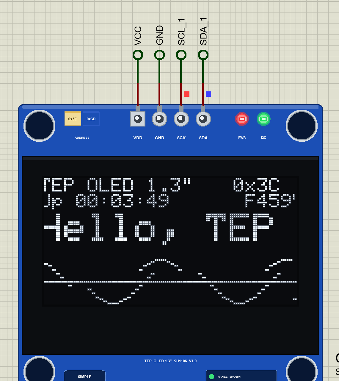
Most 1.3" modules answer at 0x3C. On the back, a small resistor chooses the address; the print says 0x78 or 0x7A, the same addresses written as 8-bit numbers (0x3C x 2 = 0x78, 0x3D x 2 = 0x7A). On our board, the ADDRESS selector does this with a click, even while the simulation runs. We clicked 0x3D on OLED1 while its sketch kept writing to 0x3C:
Nothing reaches the OLED any more and the glass keeps its last picture, exactly as a real module would. Click the selector again and the clock runs on. On a real module, a wrong address simply looks like a dead display; in our model you see the reason at once.
The SSD1306 Trap: Why an SSD1306 Sketch Shows Random Dots
Here is the mistake almost everybody makes once with a 1.3" OLED: it looks like a big 0.96", so the sketch uses the Adafruit SSD1306 library. On a real module the result is a screen full of random dots with a small band at the top that changes a little. We loaded our 0.96" demo's HEX, made with Adafruit SSD1306, into this demo:
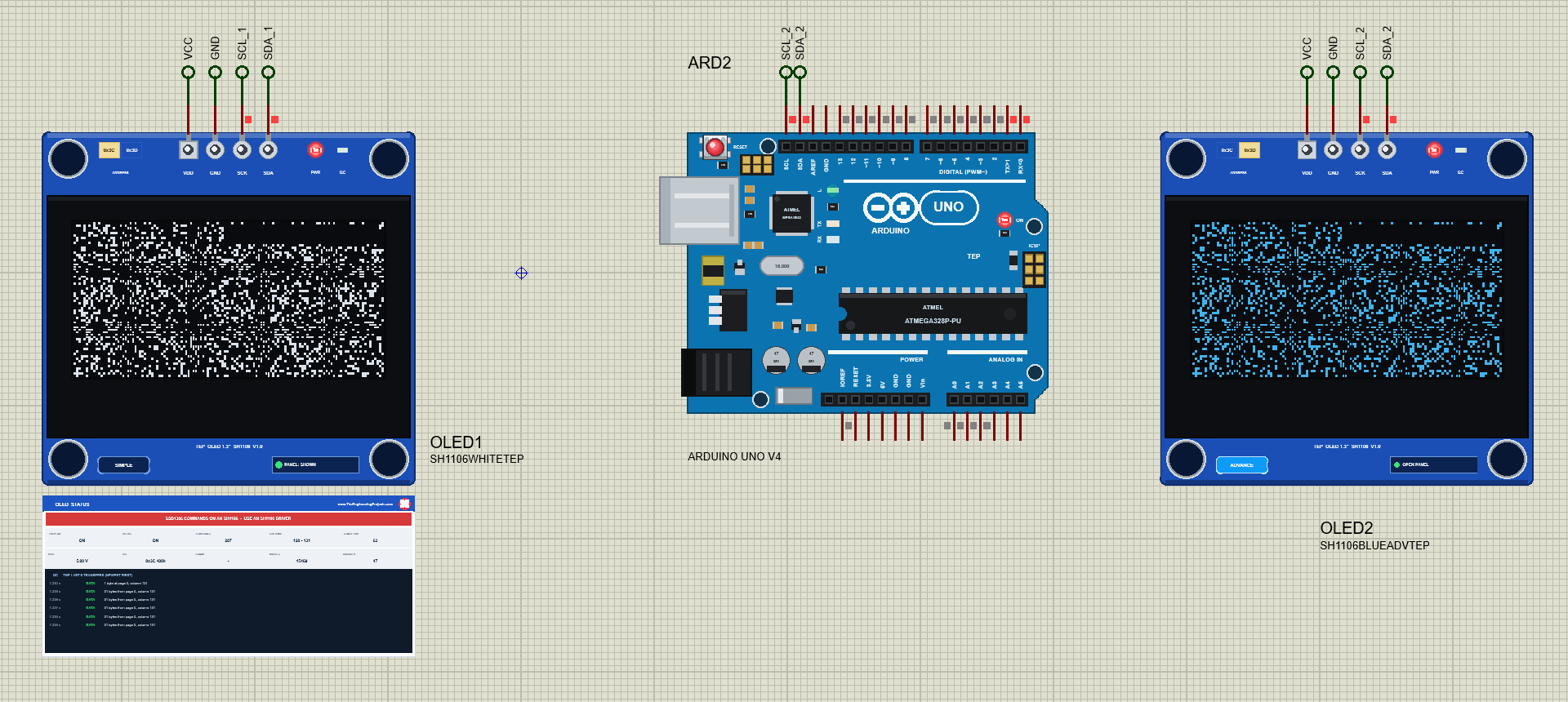
Why exactly this picture? Follow the bytes, as the model does:
- The SSD1306 start-up sends 8D 14 for its charge pump. The SH1106 has no 8D; it skips it, and the 14 becomes "column high nibble 4": the column is now 64.
- It sends 20 00 (the addressing mode): 20 is skipped, 00 sets the column's low nibble to 0.
- Every
display()sends 22 00 FF 21 00 7F (the page and column windows): 22 and 21 are skipped, 7F becomes "start line 63", which moves the whole picture down by one row. - Then come 1024 data bytes. The SH1106 never changes the page by itself, so they all go into page 0, from column 64; the column stops at 131, and the rest of the bytes pile up there.
- Pages 1 to 7 are never written: they keep the random dots every OLED has after power-on.
The next frames start at column 128, because the 00 only resets the low nibble of the column, so only the first frame ever lands in that top band. The Init check of the Advance names the culprit in red: the driver. It counts the SSD1306 commands and names the last one:
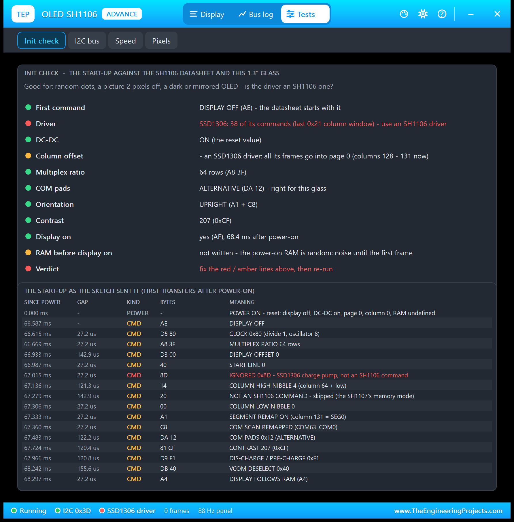
The fix is the right driver: Adafruit_SH1106G from the Adafruit SH110X library, or U8g2's SH1106 driver. The drawing code stays the same; only the display object, begin() and the colour name (SH110X_WHITE) change.
The Column Offset: A Picture 2 Pixels Too Far Left
The second classic is quieter. Some code for the SH1106, often an old or hand-written driver, writes every page from column 0. The picture then starts 2 RAM columns before the glass does. Our demo has a command for it: OFFSET 0 sends the same picture page by page from column 0, as such a driver does:
The panel shows the amber banner PICTURE 2 PIXELS LEFT - WRITES START AT COLUMN 0, THE GLASS AT 2, and a line goes to the simulation log. OFFSET 2 brings the picture back. Adafruit_SH1106G does the right thing by itself: it writes every page from column 2.
OLED SH1106 Simple: The STATUS Panel
Under the Simple OLED sits the OLED STATUS panel (see the pictures above):
| Part | What it shows |
|---|---|
| Banner | READY (SH1106 128x64, the I2C address, DISPLAY ON), WAITING FOR I2C, WRONG ADDRESS, SSD1306 COMMANDS ON AN SH1106, DISPLAY OFF, DARK - THE DC-DC IS OFF, PICTURE 2 PIXELS LEFT, MIRRORED or UPSIDE DOWN, SUPPLY REVERSED, or NO POWER |
| DISPLAY, DC-DC | Whether the display and the DC-DC converter are on |
| CONTRAST | The contrast value, 0 to 255 (Adafruit_SH1106G starts at 255) |
| COLUMNS | The columns of the newest page write: 2 - 129 for a whole page |
| START LINE | The RAM row the glass starts with (0 normally, 63 with an SSD1306 sketch) |
| VDD, I2C | The supply voltage; this OLED's address and the measured clock |
| FRAME, WRITES | How long one whole picture takes on the bus; the bytes the controller took |
| IGNORED | Commands the SH1106 does not have, and bytes sent without power |
| Bus | The last 6 transfers, newest first |
The red X in the panel's header closes it, and PANEL on the board opens it again.
OLED SH1106 Advance: The Pop-Up Window
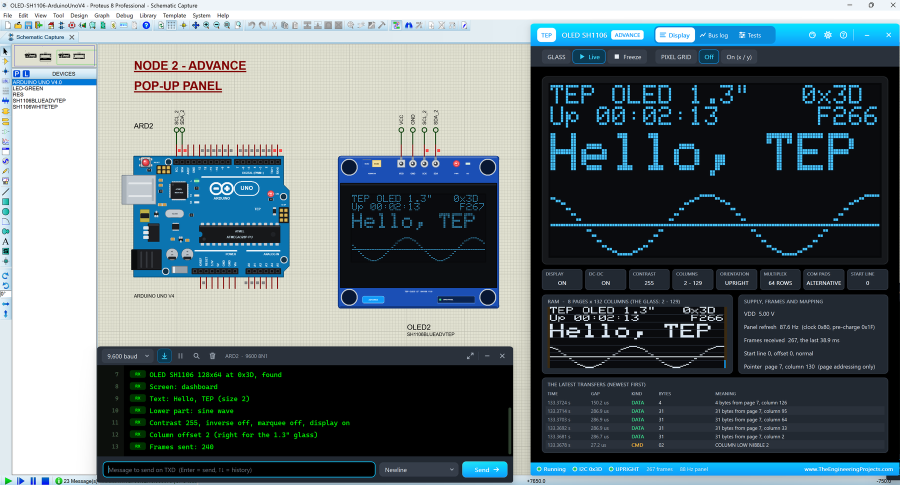
The Advance OLED keeps only the module on the schematic; OLED2, the blue Advance OLED at 0x3D, is in the featured picture at the top. At Run, the "TEP OLED SH1106 Advance" pop-up opens with the look of our TEP Serial Monitor: move it by its header, resize or minimise it, and reopen it with OPEN PANEL. The header has the Display, Bus log and Tests tabs and the theme, Settings and Help icons.
The Display Page
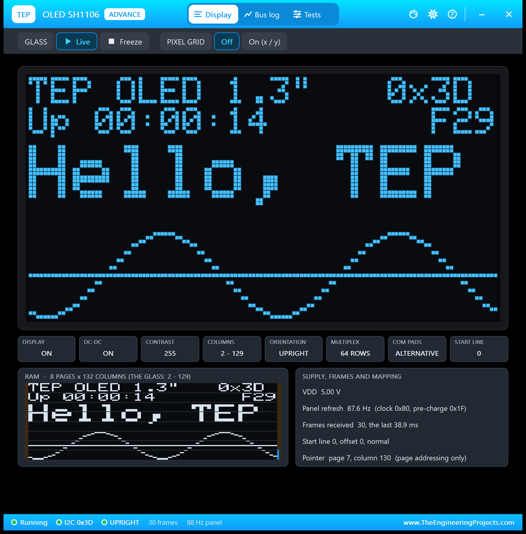
- The glass: a big copy of the OLED, every pixel visible.
- Tiles: DISPLAY, DC-DC, CONTRAST, COLUMNS, ORIENTATION, MULTIPLEX (64 ROWS), COM PADS (ALTERNATIVE) and START LINE.
- The RAM as stored: all 132 columns of the controller's memory, with the 2 columns on each side that are not on the glass marked, and the write pointer in blue.
- Supply, frames and mapping: VDD, the panel's own refresh rate (87.6 Hz), the frames received and how long the last one took, the start line and the pointer, "page addressing only".
- The latest transfers: the last page writes, newest first, such as "31 bytes from page 7, column 2".
Above the glass, GLASS: Live / Freeze holds the picture, and PIXEL GRID: On (x / y) draws a line every 8 pixels with the x and y numbers, Adafruit GFX's coordinates.
The Bus Log Page
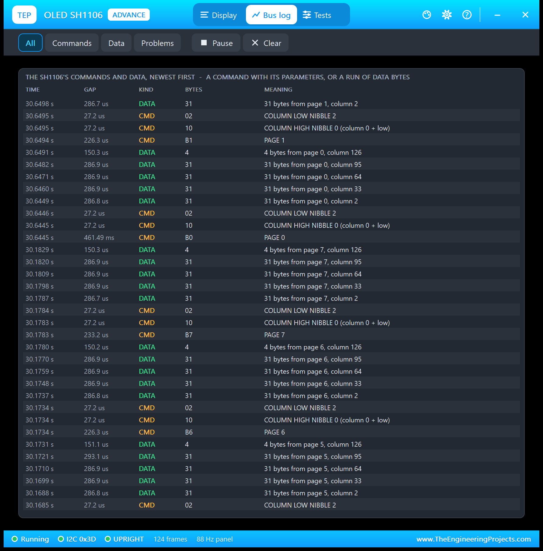
The Bus log lists what the controller took, newest first: one row per command with its parameters and meaning, or one row per run of picture data. Read it from the bottom up and you see the SH1106's way of taking a picture: for every page, three commands (the page, the column's high and low nibble, column 2) and then the data, in runs of 31 bytes because of Arduino's 32-byte Wire buffer. An SSD1306 command would show here in red.
The Tests Page: Four OLED Test Tools
The tools read the bus as the model sees it during the running simulation. Each has a bold "Good for:" line and a verdict per row: green is fine, amber means check, red means wrong. All the results below come from OLED2 in Proteus 8.5.
1. Init Check: Is the Driver an SH1106 One?
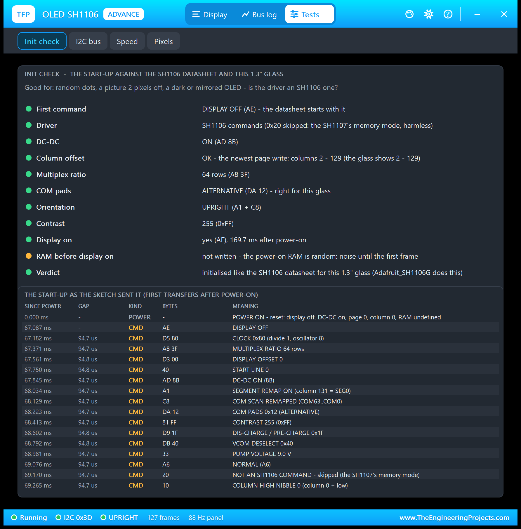
| Check | Result in the picture |
|---|---|
| First command | DISPLAY OFF (AE), as the datasheet starts |
| Driver | SH1106 commands (0x20 skipped: the SH1107's memory mode, harmless) |
| DC-DC | ON (AD 8B) |
| Column offset | OK - the newest page write: columns 2 - 129 |
| Multiplex ratio | 64 rows (A8 3F) |
| COM pads | ALTERNATIVE (DA 12), right for this glass |
| Orientation | UPRIGHT (A1 + C8) |
| Contrast | 255 (0xFF) |
| Display on | Yes (AF), 169.7 ms after power-on |
| RAM before display on | Amber: not written, so the random power-on RAM shows until the first frame |
| Verdict | Initialised like the SH1106 datasheet for this 1.3" glass |
Good for: "random dots, a picture 2 pixels off, a dark or mirrored OLED - is the driver an SH1106 one?" Two details are worth knowing. Adafruit_SH1106G also sends 20 10, the memory mode of its cousin the SH1107; the SH1106 skips the 20, so the tool lists it as harmless. And the amber row is honest, not a fault: the library's begin() switches the display on before the first picture, so a real module shows its random power-on memory for a moment too.
2. I2C Bus: Is the Sketch Talking to This OLED?
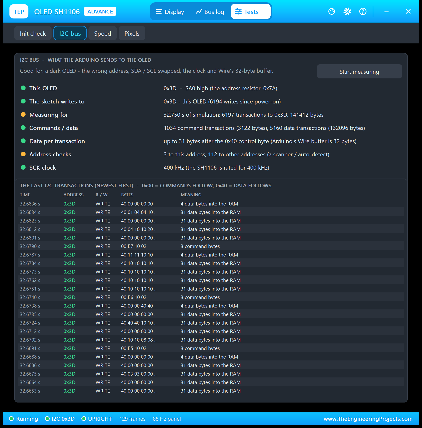
| Row | Result in the picture |
|---|---|
| This OLED | 0x3D - SA0 high (the address resistor: 0x7A) |
| The sketch writes to | 0x3D - this OLED (6194 writes since power-on) |
| Measuring for | 32.750 s of simulation: 6197 transactions to 0x3D, 141412 bytes |
| Commands / data | 1034 command transactions (3122 bytes), 5160 data transactions (132096 bytes) |
| Data per transaction | Up to 31 bytes after the 0x40 control byte (Arduino's Wire buffer is 32 bytes) |
| Address checks | 3 to this address, 112 to other addresses (a scanner / auto-detect) |
| SCK clock | 400 kHz (the SH1106 is rated for 400 kHz) |
Good for: "a dark OLED - the wrong address, SDA / SCL swapped, the clock and Wire's 32-byte buffer." The address checks come from the sketch's search at the start, from the library's own check in begin() and from the SCAN command we typed, which tries every address from 0x08 to 0x77. Notice the many command transactions: every page costs one.
3. Speed: How Fast Can the Picture Change?
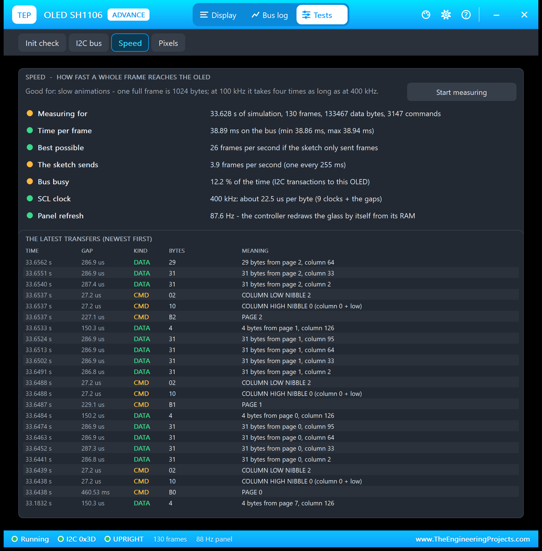
| Result | Value |
|---|---|
| Time per frame | 38.89 ms on the bus (min 38.86 ms, max 38.94 ms) |
| Best possible | 26 frames per second if the sketch only sent frames |
| The sketch sends | 3.9 frames per second (one every 255 ms; the marquee was on for part of the time) |
| Bus busy | 12.2 % of the time |
| Clock | 400 kHz: about 22.5 us per byte (9 clocks + the gaps) |
| Panel refresh | 87.6 Hz: the controller redraws the glass by itself from its RAM |
Good for: "slow animations - one full frame is 1024 bytes; at 100 kHz it takes four times as long as at 400 kHz." A whole SH1106 frame takes a little longer than an SSD1306 one, because every page needs its own command transaction. In practice the Arduino is the limit: with the marquee on, our UNO manages about 6 redraws a second, as drawing the picture takes it longer than sending it.
4. Pixels: Where Does a Pixel Live in the RAM?
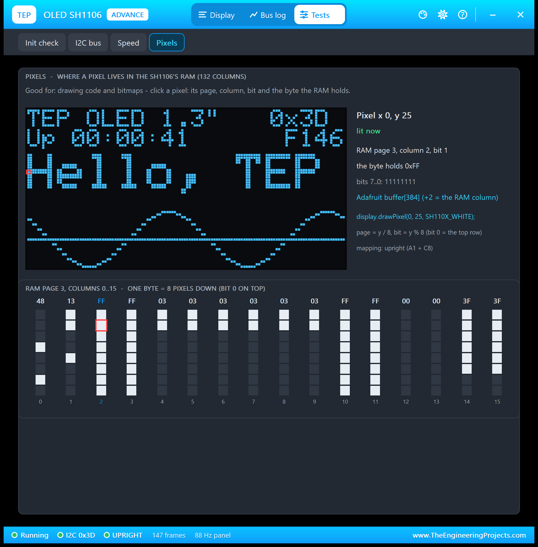
Good for: "drawing code and bitmaps - click a pixel: its page, column, bit and the byte the RAM holds." We clicked x 0, y 25, a pixel of the H: page 25 / 8 = 3, bit 25 % 8 = 1, and the RAM column is x + 2 = 2, the column offset in action. In Adafruit's 128-column buffer, the same pixel is byte 0 + 3 x 128 = 384.
OLED SH1106 with Arduino in Proteus
Open OLED-SH1106-ArduinoUnoV4.pdsprj from the Proteus Simulation folder, with OLED_SH1106_Demo.hex and both DLLs beside it. The demo runs on two of our Arduino UNO V4.0 boards from the Arduino UNO Library for Proteus V4.0: the board has working ON / L / TX / RX LEDs, a RESET button and a serial monitor built into the board, so there is no Virtual Terminal to wire. Both UNOs run the same HEX file:
- NODE 1 - SIMPLE (on-sheet panel): ARD1 with OLED1 (white, Simple, address 0x3C).
- NODE 2 - ADVANCE (pop-up panel): ARD2 with OLED2 (blue, Advance, address 0x3D).
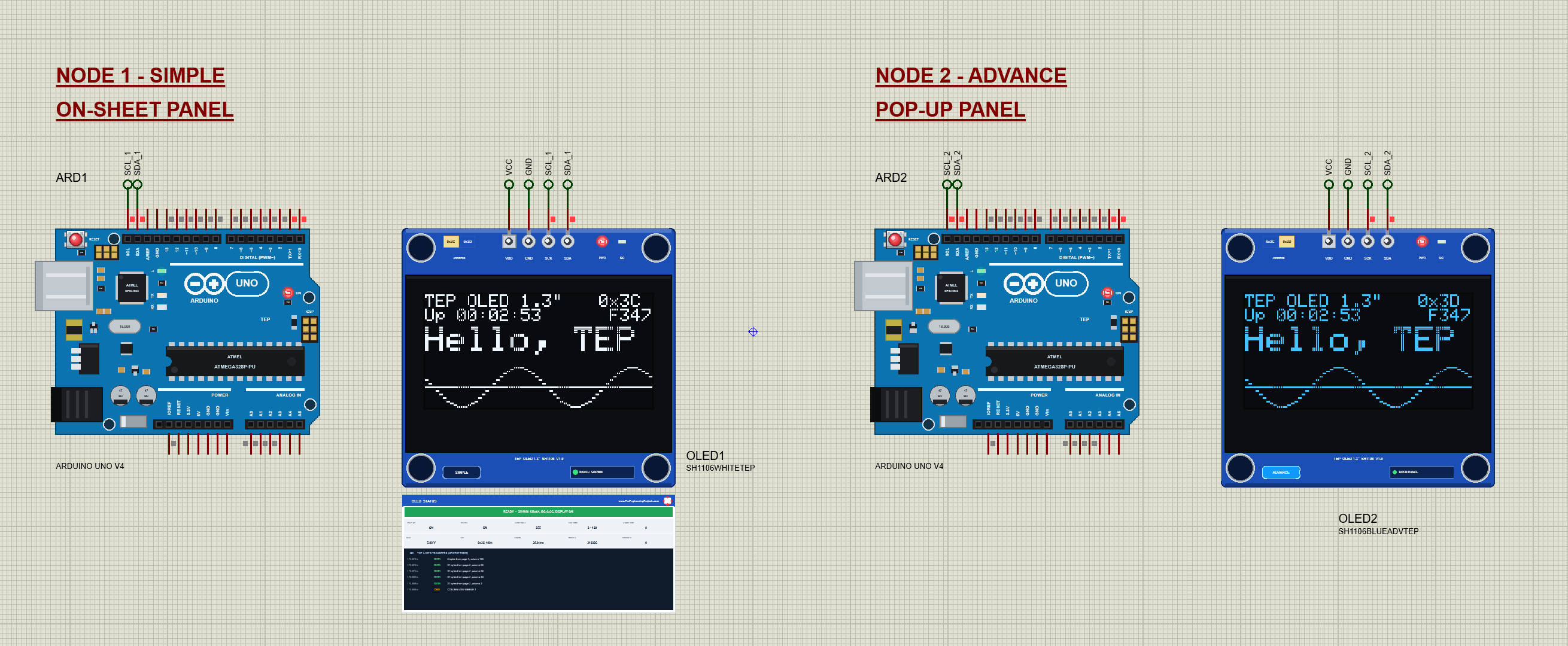
Wiring
| OLED pin | Arduino UNO | Why |
|---|---|---|
| VDD | 5V | Supply |
| GND | GND | Ground |
| SCK | SCL (= A5) | I2C clock |
| SDA | SDA (= A4) | I2C data |
| Serial monitor | Nothing to wire | Built into the UNO V4.0 on D0 / D1, like the real UNO's USB chip |
On an Arduino UNO, SDA and SCL are A4 and A5, and the UNO repeats them on the top header next to AREF (see our Introduction to Arduino UNO). Our UNO V4.0 has those header pins too, and the demo uses them. Every OLED pin goes through a short wire to a net label: terminals with the same name are connected. SDA_1 at OLED1 meets SDA_1 at ARD1's SDA pin, the board's SCK pin carries the label SCL_1, and node 2 has its own SDA_2 and SCL_2. VDD goes to the VCC label, the 5 V rail. For more about I2C addresses and the ACK, see our I2C LCD 16x2 Library for Proteus V1.0 article.
The Arduino Code
The demo sketch, OLED_SH1106_Demo V1.0, uses the Adafruit SH110X library (version 2.1.15) with the Adafruit GFX library (version 1.12.6) and Arduino's Wire library. It starts with the display object, and here is the class that matters: Adafruit_SH1106G:
#include <Wire.h>
#include <Adafruit_GFX.h>
#include <Adafruit_SH110X.h>

Adafruit_SH1106G display(128, 64, &Wire, -1);   // width, height, the I2C bus, no reset pin
The sketch finds the address itself with an I2C address check, an empty write that a device answers with ACK, then starts the display. Note the arguments of begin(): the address and the reset flag; there is no charge pump to switch on:
bool answers(byte a) {                 // an address check: does a device ACK?
  Wire.beginTransmission(a);
  return Wire.endTransmission() == 0;
}
if (!display.begin(address, true)) {Everything the sketch draws goes into the buffer first, in SH110X_WHITE; display() sends it page by page from column 2, and the demo counts the frames, the "F" number on the glass:
display.setTextColor(SH110X_WHITE);void show() {
if (columnOffset == 2) display.display();
else sendPages(columnOffset);
frames++;
}For OFFSET 0, the sketch sends the pages itself with Wire. This is the SH1106's way of taking a picture, and the best way to understand the controller: for every page, a command transaction with the page and the two nibbles of the column, then the data in pieces of 16 bytes:
  for (byte p = 0; p < 8; p++) {
    Wire.beginTransmission(address);
    Wire.write(0x00);                  // control byte: commands follow
    Wire.write(0xB0 + p);              // the page
    Wire.write(0x10 + (offset >> 4));  // the column's high nibble
    Wire.write(offset & 0x0F);         // and its low nibble
    Wire.endTransmission();
    for (byte c = 0; c < 128; c += 16) {
      Wire.beginTransmission(address);
      Wire.write(0x40);                // control byte: data follows
      Wire.write(buf + p * 128 + c, 16);
      Wire.endTransmission();
    }
  }
The SH1106 cannot scroll by itself, so the MARQUEE moves the text in the sketch: the big line is drawn 4 pixels further left on every redraw, ten times a second, and starts again from the right:
display.setCursor(marquee ? marqueeX : 0, 18); if (marquee) {
marqueeX -= 4;
if (marqueeX < -(int)(strlen(text) * 6 * textSize)) marqueeX = 128;
}Display on and off use the library's command function with the SH110X names:
display.oled_command(displayOn ? SH110X_DISPLAYON : SH110X_DISPLAYOFF);To change the sketch, install the libraries from the Library Manager, export a new HEX file and load it into both UNOs; see How to get the HEX file from Arduino. New to Arduino? Start with our Arduino Tutorial for Beginners.
Serial Monitor Commands
| Command | What it does |
|---|---|
| HELP | The command list |
| STATUS | The address, the screen, the text, the lower part, contrast, inverse, marquee, display, the column offset and the frames |
| SCAN | Every I2C device on the bus (0x08 - 0x77) |
| TEXT <text> | The big line (up to 21 characters; 10 fit at size 2) |
| SIZE <1-3> | Its text size |
| MARQUEE ON / OFF | The text moves across the glass; the sketch redraws it |
| GRAPH / BAR <0-100> | A moving sine wave / a bar in the lower part |
| LOGO, SHAPES, DASH | The TEP logo, GFX shapes with a frame round the whole glass, the dashboard again |
| INVERT ON / OFF | Inverse: the controller swaps lit and dark pixels |
| CONTRAST <0-255> | The brightness (Adafruit_SH1106G starts at 255) |
| DISPLAY ON / OFF | The panel on or off (the RAM is kept) |
| OFFSET 0 / 2 | The column the pages start at: 2 is right, 0 shows the 2-pixel shift |
| CLEAR | An empty screen (DASH brings the dashboard back) |
How to Run the Demo
- Press Run. Both UNOs' monitor windows and OLED2's pop-up open; move them aside, as they open over the schematic. The OLEDs show the TEP logo for a second, then the dashboard.
- Type STATUS, OFFSET 0 and OFFSET 2 in ARD1's monitor; SCAN, MARQUEE ON and SHAPES in ARD2's.
- Click the ADDRESS selector of OLED1 and watch the panel; click it again.
- On OLED2's pop-up, turn on the pixel grid, look at the Bus log, and run the four tools.
- Press the RESET button of a UNO: the bootloader flashes L, and the sketch starts again 1 s later.
OLED SH1106 Proteus Simulation Results
The Built-in Serial Monitor in Its Simple Interface
Each Arduino UNO V4.0 carries its own copy of our TEP Serial Monitor Advance, wired inside the board to D0 / D1 like the USB chip of a real UNO. Its window, "TEP Arduino UNO - ARD1", opens at Run, and a click on the board's USB port opens it again. The screenshots show its Simple interface: only the log and the line to send.
- Switch to it: press Ctrl+Shift+U, or use the monitor's ... menu.
- Back to the full view: press Esc; the full view has the Board, Monitor and Plotter tabs.
Read all about the monitor in TEP Serial Monitor Advance for Proteus.
ARD1: STATUS and OFFSET 0
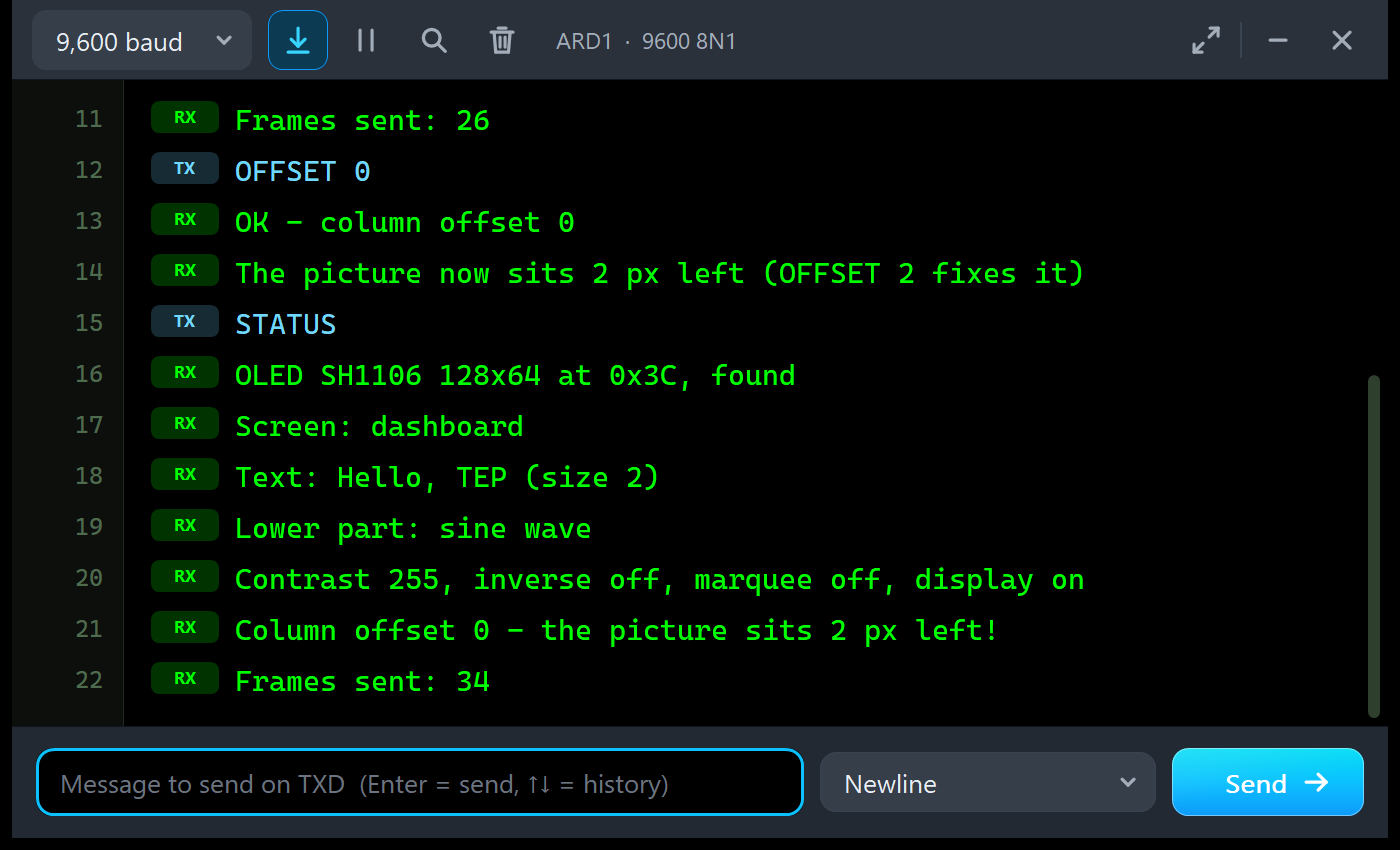
OLED SH1106 V1.0 demo - The Engineering Projects
OLED found at 0x3C
Type HELP for the commands
STATUS
OLED SH1106 128x64 at 0x3C, found
Screen: dashboard
Text: Hello, TEP (size 2)
Lower part: sine wave
Contrast 255, inverse off, marquee off, display on
Column offset 2 (right for the 1.3" glass)
Frames sent: 26
OFFSET 0
OK - column offset 0
The picture now sits 2 px left (OFFSET 2 fixes it)
STATUS
OLED SH1106 128x64 at 0x3C, found
Screen: dashboard
Text: Hello, TEP (size 2)
Lower part: sine wave
Contrast 255, inverse off, marquee off, display on
Column offset 0 - the picture sits 2 px left!
Frames sent: 34
The second line is the address search at work: the sketch found the OLED at 0x3C by itself. The two STATUS answers show the column offset before and after OFFSET 0.
ARD2: SCAN and MARQUEE
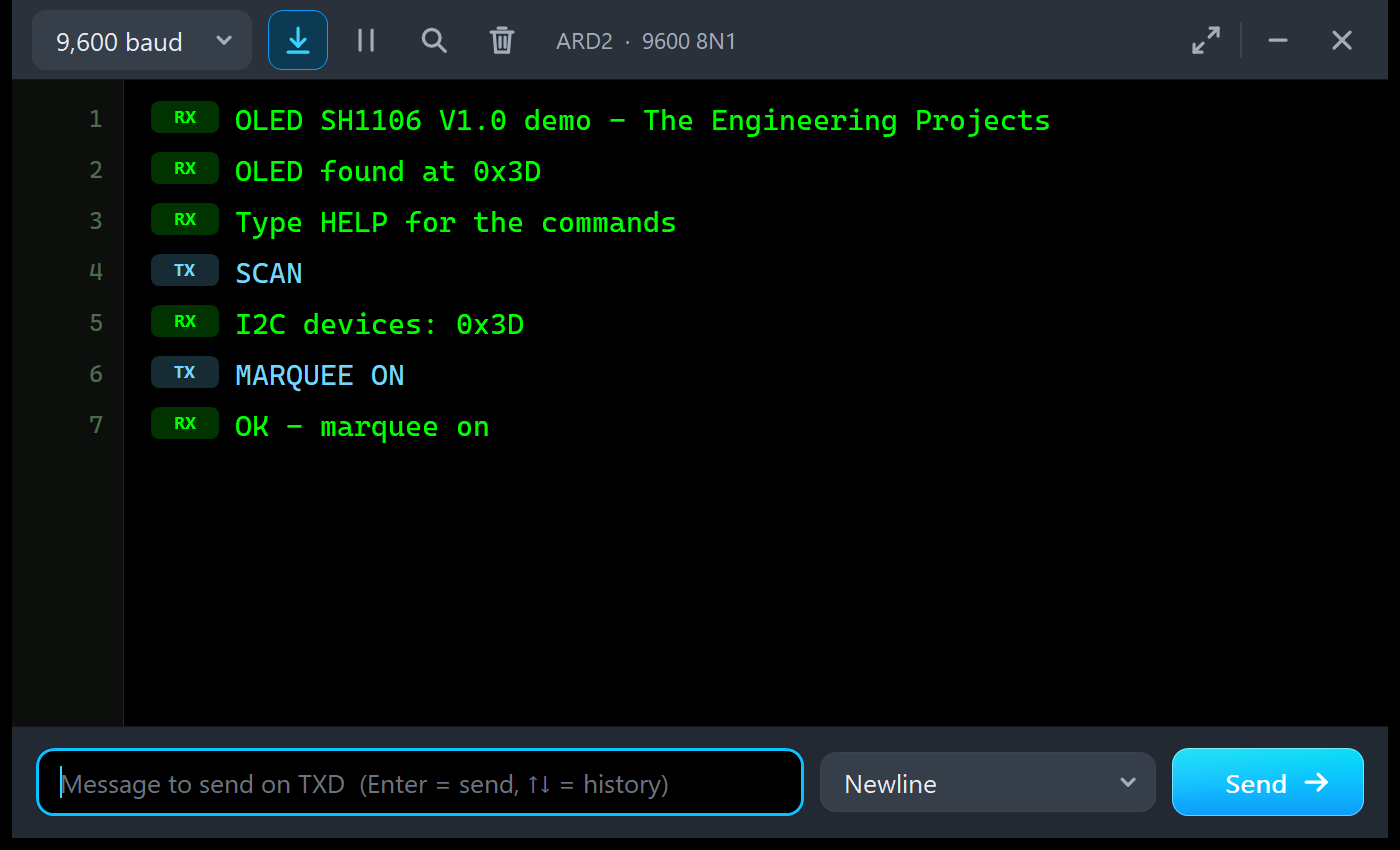
OLED SH1106 V1.0 demo - The Engineering Projects
OLED found at 0x3D
Type HELP for the commands
SCAN
I2C devices: 0x3D
MARQUEE ON
OK - marquee on
SCAN finds one device, the OLED at 0x3D: each UNO has its own I2C bus in this demo. With MARQUEE ON, the big line slides across the blue glass from right to left.
Troubleshooting
- The glass stays black and the PWR LED is off: no power. Check VDD and GND (the panel says NO POWER with the voltage; the module needs 3.3 to 5 V).
- SUPPLY REVERSED: VDD and GND are swapped. This board's pins are VDD, GND, SCK, SDA, not GND, VCC like the 0.96" board.
- WAITING FOR I2C: nothing reached this address. Check SDA and SCK (swapped lines look the same: nothing works), and that the sketch runs.
- WRONG ADDRESS: the sketch writes to another address. Change the address in
display.begin(), or the ADDRESS property or the selector; the I2C bus tool shows both. - Random dots everywhere / SSD1306 COMMANDS ON AN SH1106: the sketch uses an SSD1306 library. Use
Adafruit_SH1106Gor U8g2's SH1106 driver. - PICTURE 2 PIXELS LEFT: the driver writes from column 0. Use an SH1106 driver, which starts at column 2.
- Random dots for a moment at the start: the RAM before the first frame. Call
display.display()after drawing. - Mirrored or upside down: the remap commands (A0 / A1, C0 / C8);
display.setRotation(2)turns the picture in software instead. - The part or the UNO is not simulated, or no monitor window: TEPOLED.DLL or TEPARDUINO.DLL is missing from MODELS and the project folder; a closed monitor opens again with a click on the UNO's USB port.
- The Advance pop-up does not appear: click OPEN PANEL on the board, or turn "Open the panel at Run" back on in Settings.
Things to Know Before Using a Real 1.3" OLED
The demo sketch uses only Wire, the Adafruit libraries and Serial, so it runs on a real UNO and 1.3" OLED too. Keep in mind:
- Check the pin order on YOUR module: most are VDD, GND, SCK, SDA, some are GND, VDD, SCK, SDA. Swapped supply pins can kill the module.
- Check the controller: most 1.3" 128x64 modules use the SH1106. If yours shows random dots with an SSD1306 library, it is one. A few 1.3" modules use an SSD1306 or SSD1309; then the SSD1306 library is right.
- Find the address: run an I2C scanner (or the demo's SCAN). Most modules are 0x3C.
- RAM: Adafruit_SH1106G keeps a 1 KB picture buffer, half of an UNO's RAM; our demo uses 785 bytes more. Keep texts in flash with
F("..."). - No hardware scrolling: move the picture in the sketch, as our MARQUEE does.
- Supply and pull-ups: the module has its own regulator and SDA / SCK pull-ups, so it runs from 3.3 V and from 5 V; 400 kHz I2C is fine.
- Burn-in: OLED pixels age; turn the display off or dim it when nobody looks.
Limitations of the Simulation
- Not modelled: reading from the OLED (libraries never read it; a read is not acknowledged), the SPI interface of the 7-pin modules, the effect of the pre-charge, VCOM and pump-voltage settings on the picture, I2C timing violations, the current draw, damage from a reversed supply (the model only warns) and pixel ageing.
- The board is drawn at twice the real size; the LEDs, the address selector, the badge and the panel button are TEP additions.
- The model is our own implementation, written from the SH1106 datasheet. SH1106 is a Sino Wealth part; this library is not made or endorsed by Sino Wealth, Adafruit or Labcenter.
- Licences: the demo sketch uses Adafruit SH110X 2.1.15, Adafruit GFX 1.12.6 (BSD licence), Adafruit BusIO and Arduino's Wire library. The HEX file contains them and the Arduino AVR core 1.8.6, which includes LGPL-licensed code; its source code is on GitHub. The README holds the Adafruit licence texts.
- Tested in Proteus 8.5 in October 2026 (the demo as shipped on two Arduino UNO V4.0 boards with their built-in monitors, all four devices, the dashboard, the Serial commands, OFFSET and the marquee, the address selector, the panel, the pop-up and the four tools, the SSD1306 trap, the reversed supply, and every screenshot here; about 0.4 x real time with the pop-up and both monitors open on a busy PC) and with automatic PC checks, 0 failed: 57 with the real demo sketch and the unmodified Adafruit libraries talking bit by bit to the model, where the glass equals Adafruit's own buffer after every frame, 38 on the SH1106 controller, and the demo project read back from disk. Proteus 7 is not supported.
So, that was all about the OLED SH1106 Library for Proteus V1.0. I hope the 132-column RAM, the SSD1306 trap made visible and the column offset make the 1.3" OLED easy to understand, so your display works the first time you wire a real one. If you use the OLED SH1106 Library for Proteus in a project, please share your feedback in the comments or in our forum, and if you have any questions, ask in the comments and I will help you out. Till the next tutorial, take care and have fun!
Comments
0