


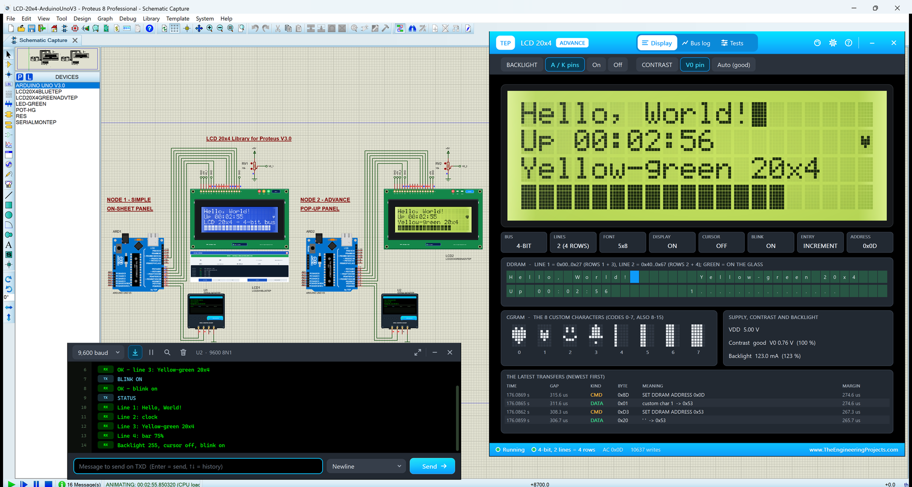
LCD 20x4 Library for Proteus V3.0 (HD44780 + Arduino)


Hello friends, I hope you all are doing great. Today, I am going to share the new LCD 20x4 Library for Proteus V3.0. The 20x4 character LCD, the big blue or yellow-green "2004" display with 16 pins, shows four rows of 20 characters, 80 characters in all, so it is the LCD to pick when a 16x2 is too small for your menu, your sensor readings or your status screen. With this LCD 20x4 Library for Proteus, your sketch writes to an LCD that behaves like the real one: the real HD44780 timing, the contrast pot, the backlight, your own characters, and the strange row order of every 20x4.
Version 3.0 is the next version of our 20x4 LCD library, and like our LCD 16x2 Library for Proteus V3.0 it is our own HD44780 model this time, not a new symbol on top of Proteus's built-in LCD: a 20x4 glass wired to the Arduino through the 16-pin header. (The same LCD with a 4-wire backpack is our I2C LCD 20x4 Library for Proteus V1.0.) You get four devices: a blue and a yellow-green LCD, each as LCD 20x4 Simple, with a live STATUS panel on the schematic, and LCD 20x4 Advance, with a pop-up window, a bus log and four LCD test tools. The demo runs a small dashboard with Arduino's LiquidCrystal library on two Arduino UNOs, with the Simple interface of our TEP Serial Monitor.
NOTICE: This library is very special to our team. A 20x4 is not just a 16x2 with more rows: its controller has two lines, and each line runs over two rows of the glass. We wrote the HD44780 ourselves and wired it to the 20x4 glass exactly like the real module, with the real timing, the contrast and the backlight. It took our team a lot of hard work and many test runs. Your feedback is the fuel that keeps us going, so please tell us what you think in the comments below or in the LCD Library board of our forum. And if our free libraries help you, you can buy us a coffee. So, let's get started with the LCD 20x4 Library for Proteus V3.0:
What is a 20x4 LCD?
A 20x4 LCD is a character display: 4 rows with 20 characters each. Every character is a small block of 5x8 dots. The module you buy, often sold as the "2004A", is a green board of about 98 x 60 mm with a big glass in a metal frame, a 16-pin header on the top edge and an LED backlight. The two common colours are blue (white characters on a blue backlight) and yellow-green (dark characters on a yellow-green backlight).
On the back sits the same HD44780 controller as on a 16x2. Your Arduino never draws dots: it sends commands (clear, move the cursor, display on) and characters (codes such as 0x48 for "H") over a parallel bus, and the controller turns each code into dots from its character ROM. For a deeper look at the module, read our Introduction to 20x4 LCD Module.
The 20x4 LCD at a Glance
| Feature | Value |
|---|---|
| Display | 4 rows x 20 characters, each 5x8 dots |
| Board | About 98 x 60 mm, the 16-pin header on the top edge |
| Controller | HD44780 (or compatible): 80 bytes of display RAM, a character ROM and 8 own characters |
| Bus | 8-bit (D0 - D7) or 4-bit (D4 - D7), plus RS, RW and E |
| Supply | 5 V on VDD, ground on VSS |
| Contrast | The voltage on V0, set with a 10k pot |
| Backlight | An LED on A (+) and K (-); the blue one takes about 20 mA, the yellow-green one about 120 mA |
| Timing | 37 us per command, 41 us per character, 1.52 ms for clear and home |
| Arduino library | LiquidCrystal (comes with the Arduino IDE): lcd.begin(20, 4) |
LCD Terms You Will See in This Article
| Term | Meaning |
|---|---|
| DDRAM | Display data RAM: the character codes, 80 bytes in two lines of 40 |
| Line / row | A line is one of the controller's two 40-byte lines; a row is what you see on the glass |
| CGRAM | Character generator RAM: room for 8 characters you design (codes 0 to 7) |
| Busy time | How long the controller needs after a byte; a byte sent earlier is lost |
| RS | Register select: 0 = command, 1 = character |
| E | Enable: the controller takes the byte when E falls |
| V0 | The contrast pin: the bigger VDD - V0, the darker the dots |
| A / K | Anode and cathode of the backlight LED |
How the HD44780 Drives a 20x4 Glass
Commands, Characters and the Busy Time
Every byte travels with RS: RS = 0 makes it a command, RS = 1 a character. A character goes into DDRAM at the address counter, and the address moves on by one. In 4-bit mode, which LiquidCrystal uses with 6 wires, each byte is sent as two halves, so E pulses twice per byte. After most commands the controller is busy for 37 us, after a character for 41 us, after clear or home for 1.52 ms. A byte that arrives while it is busy is simply lost, on a real LCD and in our model; LiquidCrystal waits long enough after every byte.
Two Lines on Four Rows
Here is the part that surprises everybody the first time. The HD44780 knows only two lines, each 40 characters long in its memory. A 16x2 shows the first 16 characters of each line. A 20x4 shows line 1 on rows 1 and 3 and line 2 on rows 2 and 4: the first 20 characters of a line on the upper row, the next 20 on the row two places below. So the controller still runs in 2-line mode, and the four rows have these addresses:
| Row on the glass | setCursor() | DDRAM addresses | Controller line |
|---|---|---|---|
| Row 1 | lcd.setCursor(0, 0) | 0x00 - 0x13 | Line 1, characters 1 - 20 |
| Row 2 | lcd.setCursor(0, 1) | 0x40 - 0x53 | Line 2, characters 1 - 20 |
| Row 3 | lcd.setCursor(0, 2) | 0x14 - 0x27 | Line 1, characters 21 - 40 |
| Row 4 | lcd.setCursor(0, 3) | 0x54 - 0x67 | Line 2, characters 21 - 40 |
Three things follow from it. A text that runs past the end of row 1 continues on row 3, not row 2, so print every row after its own setCursor(0, row). A sketch that calls lcd.begin(16, 2) on a 20x4 cannot reach rows 3 and 4 properly. And a display shift moves rows 1 and 3 together, as one line: our demo's SCROLL shows it below.
The Start-Up and the Two Rows of Blocks
After power-on the controller is in 8-bit mode with one line and the display off. In one-line mode it drives line 1 only, and on a 20x4 line 1 is rows 1 and 3, so a 20x4 that was never initialised shows two rows of dark blocks, rows 1 and 3. lcd.begin(20, 4) sends the start-up sequence from the datasheet: three wake-up commands, the switch to 4-bit mode, 2 lines, display on, clear and the entry mode.
Contrast, Backlight and Your Own Characters
The dots darken with the voltage across the liquid crystal, VDD - V0, set with a 10k pot. Too little voltage and the characters fade out; too much and the empty dots turn dark as well. The backlight is an LED with a series resistor that you can dim with analogWrite() on a PWM pin. CGRAM holds 8 characters of your own, codes 0 to 7; lcd.createChar(n, rows) writes one and lcd.write(byte(n)) prints it. One trap: createChar() leaves the address counter in CGRAM, so call lcd.setCursor() before you print again.
What's New in LCD 20x4 Library for Proteus V3.0
Here is what version 3.0 brings:
- A real 20x4 glass on our HD44780 model: line 1 on rows 1 and 3, line 2 on rows 2 and 4, two rows of blocks before initialisation, and a display shift that moves the rows the way a real 20x4 does.
- Our own HD44780 model (
TEPLCD.DLL): the real busy times (bytes sent too fast are lost and reported), CGRAM, the full A00 ROM, reading back, cursor and blink. - Real analog pins: VDD and VSS, the contrast pin V0 (turn a pot and watch the contrast change) and the LED backlight A / K (dim it with PWM). Pins you leave open get friendly defaults.
- Four devices in
TEPLCD20X4.LIB: blue and yellow-green, each Simple and Advance. - Four LCD test tools on the Advance: Init check, Timing, Speed and Characters.
- A two-UNO dashboard demo with LiquidCrystal: a clock, a bar that fills once a minute, four text lines, and Serial commands such as TEXT1 to TEXT4, BAR, MINUTE, LIGHT and SCROLL.
- A compact package: about 1.42 MB, without the C++ source code.
The model file TEPLCD.DLL is shared with our LCD 16x2 V3.0, I2C LCD 16x2 V1.0 and I2C LCD 20x4 V1.0 libraries and runs their devices too. If you have them, keep this newer DLL. Earlier versions of our LCD library use other file names, so you can keep them installed next to V3.0.
LCD 20x4 Simple vs LCD 20x4 Advance
All four devices share one model and the same LCD. They differ in the glass colour and in where you see the extras:
| Device | Name in Pick Devices | Glass | Extras |
|---|---|---|---|
| LCD20X4BLUETEP | LCD 20x4 V3.0 Blue - Simple | Blue, white characters | STATUS panel on the sheet |
| LCD20X4BLUEADVTEP | LCD 20x4 V3.0 Blue - Advance | Blue, white characters | Pop-up window and tools |
| LCD20X4GREENTEP | LCD 20x4 V3.0 Yellow-green - Simple | Yellow-green, dark characters | STATUS panel on the sheet |
| LCD20X4GREENADVTEP | LCD 20x4 V3.0 Yellow-green - Advance | Yellow-green, dark characters | Pop-up window and tools |
Pick a Simple LCD when you want to see the LCD's state right on the schematic. Pick an Advance LCD when the schematic is crowded, or when you want the bus log and the test tools.
Download LCD 20x4 Library for Proteus
Click the button below to download LCD-20x4-Library-for-Proteus-v3.0.zip (about 1.42 MB, without the C++ source code):
LCD 20x4 Library for Proteus V3.0- README.txt: a detailed guide to the files, the wiring, the row order, the model, the test tools and real hardware.
- Proteus Library Files:
TEPLCD20X4.LIB(all four devices),TEPSERIALMON.LIBand our Arduino UNO libraryArduinoV3TEP.LIB/ArduinoV3TEP.IDX. - Proteus Model Files:
TEPLCD.DLLandTEPSERIALMON.DLL. - Proteus Simulation:
LCD-20x4-ArduinoUnoV3.pdsprj,LCD_20x4_Demo.hex(both UNOs run it) and copies of both DLLs. - Arduino Code:
LCD_20x4_Demo.ino, the demo sketch. It uses Arduino's LiquidCrystal library, which comes with the Arduino IDE.
Want all four LCDs? This LCD is also part of our LCD Library for Proteus V3.0: the LCD 16x2, LCD 20x4, I2C LCD 16x2 and I2C LCD 20x4 in one library (16 parts, one DLL), with a demo in which one Arduino UNO drives all four.
No Proteus yet? Read How to Download and Install Proteus 7 and 8. New to libraries? Follow How to Install a New Library in Proteus.
How to Install LCD 20x4 Library for Proteus
- Close Proteus and extract the whole zip file to a normal folder, for example your Desktop.
- Copy the four files from Proteus Library Files into the LIBRARY folder, usually
C:\Program Files (x86)\Labcenter Electronics\Proteus 8 Professional\LIBRARY(on some PCsC:\ProgramData\Labcenter Electronics\Proteus 8 Professional\LIBRARY; use the folder that already holds Proteus's own .LIB files). - Copy
TEPLCD.DLLandTEPSERIALMON.DLLfrom Proteus Model Files into the MODELS folder. - Delete
TEPLCD20X4.IDXfrom the LIBRARY folder if there is one; Proteus makes a new index. - Start Proteus, press P and search for LCD20X4. You get the four devices.
Tip: the demo project needs the .hex file and the two DLLs beside it, so keep the Proteus Simulation folder together. The library was tested in Proteus 8.5; Proteus 7 is not supported.
The 20x4 LCD Board in Proteus
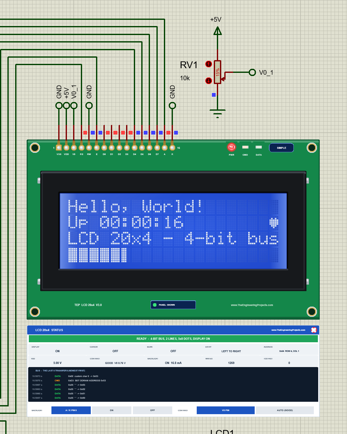
We drew the LCD as a clean TEP board in the real proportions and colours of a 2004A module: the green PCB with four mounting holes, the 16 gold pads with the pin names, the big black metal frame and the glass with all 80 character cells. At Run, the glass glows with the backlight, and every character is drawn dot by dot with the contrast. Here is LCD1, the blue Simple LCD, running the demo's dashboard:
Pinout
| Pin | Name | What it does | Demo connection |
|---|---|---|---|
| 1 | VSS | Ground | GND |
| 2 | VDD | Supply, 5 V | +5V |
| 3 | V0 | Contrast voltage | The wiper of the 10k pot |
| 4 | RS | Register select: command (0) or character (1) | Arduino D2 |
| 5 | RW | Read (1) or write (0) | GND (the sketch only writes) |
| 6 | E | Enable: the byte is taken when E falls | Arduino D3 |
| 7 - 10 | D0 - D3 | Data bus, low half | Not connected (4-bit bus) |
| 11 - 14 | D4 - D7 | Data bus, high half | Arduino D4 - D7 |
| 15 | A | Backlight LED anode (+) | D10 (LCD1, PWM) or +5V (LCD2) |
| 16 | K | Backlight LED cathode (-) | GND |
LEDs, Indicators and Properties
| Indicator | What it shows | On the real board? |
|---|---|---|
| The backlight | The glass glows with the current through A / K (dim with PWM) | Yes |
| PWR LED (red) | Lit while the LCD has power (VDD above 4 V) | TEP addition |
| CMD LED (orange) | Flashes when a command arrives | TEP addition |
| DATA LED (green) | Flashes when a character arrives | TEP addition |
| SIMPLE / ADVANCE badge, PANEL / OPEN PANEL | Which device this is, and the panel button | TEP addition |
| Property | Meaning | Default |
|---|---|---|
| PANEL | Simple devices only: the STATUS panel at the start, OPEN or CLOSED | OPEN |
| BACKLIGHT | PINS (from A / K), ON or OFF (forced) | PINS |
| CONTRAST | PIN (from V0) or AUTO (always good) | PIN |
If you leave pins open, the model is friendly: an open VDD counts as 5 V, an open V0 as good contrast, and an open A as backlight on. So you can start with just the bus wires and add the analog parts later.
The 20x4 Row Order in Proteus
Our model shows the row order exactly like a real 20x4. First the start-up: we started the demo paused, at time 0, before the sketch's first command. The controller has just reset itself, it is in one-line mode, and the glass shows dark blocks on rows 1 and 3, while rows 2 and 4 stay empty:
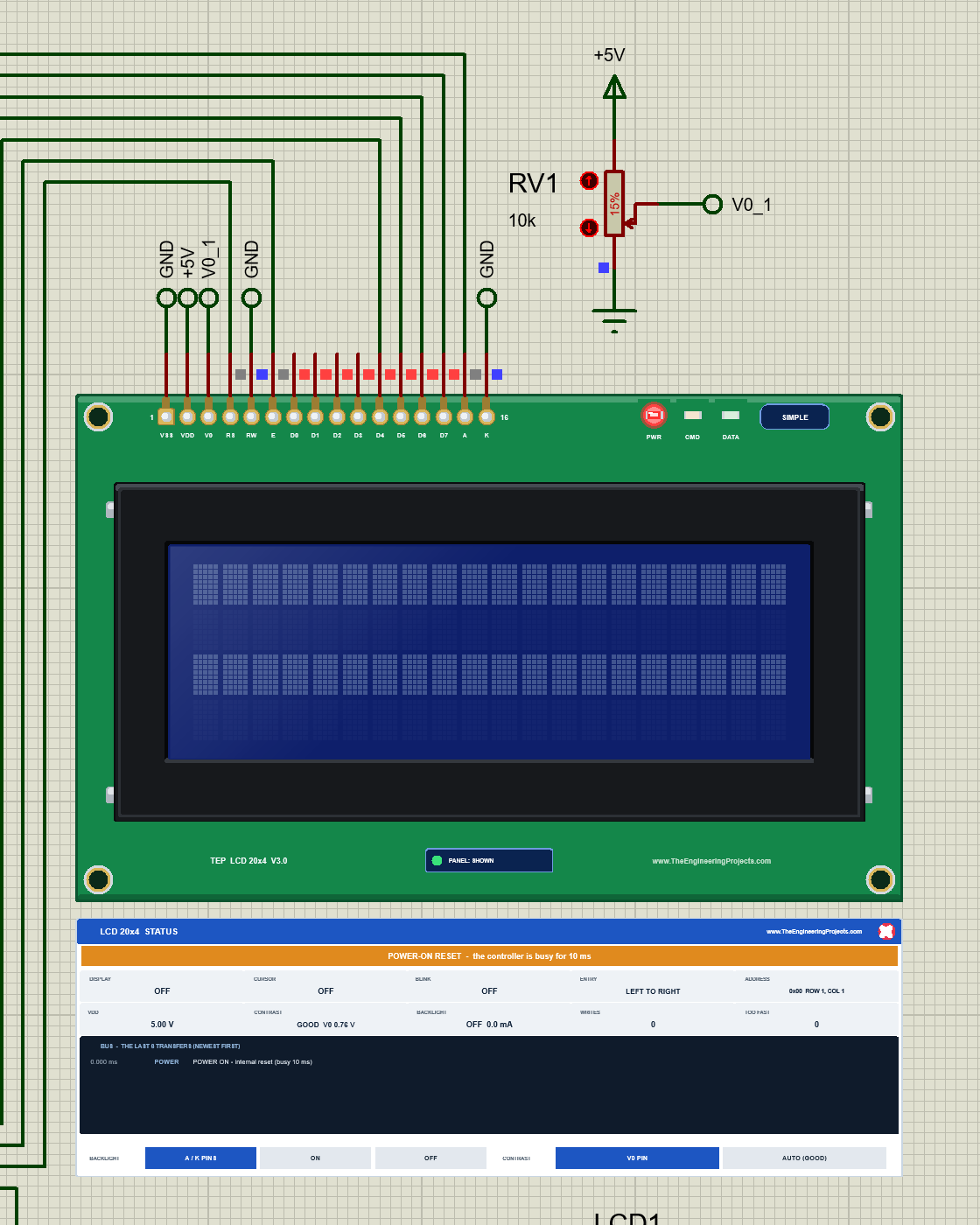
On a real 20x4, this picture means: the module has power and the contrast is fine, but the sketch never reached the LCD. Check the pins in LiquidCrystal lcd(...) and the wires to RS, E and D4 to D7.
Now the display shift. The demo's SCROLL command moves the whole display 20 steps to the left, one step every 200 ms, and then 20 steps back. Each controller line is 40 characters long and wraps around, so after 20 steps the second half of each line is on the upper row: rows 1 and 3 have swapped places, and so have rows 2 and 4:
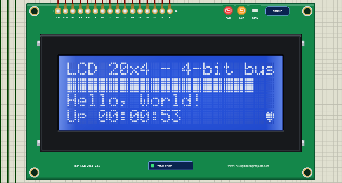
On a 16x2 the same command slides the text off the glass and back. On a 20x4 the text of row 1 slides into row 3. Keep that in mind before you use scrollDisplayLeft() on a 20x4.
LCD 20x4 Simple: The STATUS Panel
Under the Simple LCD sits the LCD 20x4 STATUS panel (see the pictures above):
| Part | What it shows |
|---|---|
| Banner | The state in words: READY (with the bus, lines and font), NOT INITIALISED, TOO FAST, NO POWER, DISPLAY OFF or POWER-ON RESET |
| DISPLAY, CURSOR, BLINK, ENTRY | The display, cursor, blink and entry mode flags |
| ADDRESS | Where the address counter points, with the row and column on the 20x4 (0x54 = ROW 4, COL 1) |
| VDD, CONTRAST | The supply voltage, and the contrast with V0 (GOOD, WEAK, TOO LOW or TOO HIGH) |
| BACKLIGHT | The backlight current (ON, DIM or OFF) |
| WRITES, TOO FAST | Bytes taken, and bytes lost because they came during the busy time |
| Bus | The last 6 transfers, newest first: time, CMD or DATA and what each byte means |
| Buttons | BACKLIGHT (A / K PINS, ON, OFF) and CONTRAST (V0 PIN, AUTO (GOOD)) override the pins for this run |
The red X in the panel's header closes it, and PANEL on the board opens it again.
Turning the Contrast Pot
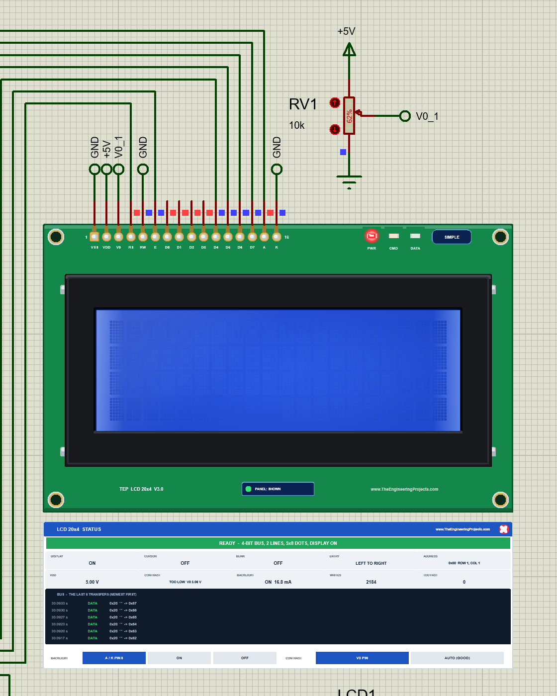
Click the arrows on RV1 (click and hold to move fast) and watch the glass. At 15 % the wiper gives V0 = 0.76 V and the contrast is GOOD. Turn it up to 62 %: V0 rises to 3.08 V, the voltage across the crystal drops, and all four rows fade until they are nearly gone. The panel says TOO LOW:
Now turn RV1 all the way down to 0 %. V0 is 0 V, the full 5 V is across the crystal, and even the empty dots of all 80 cells turn dark. The panel says TOO HIGH:
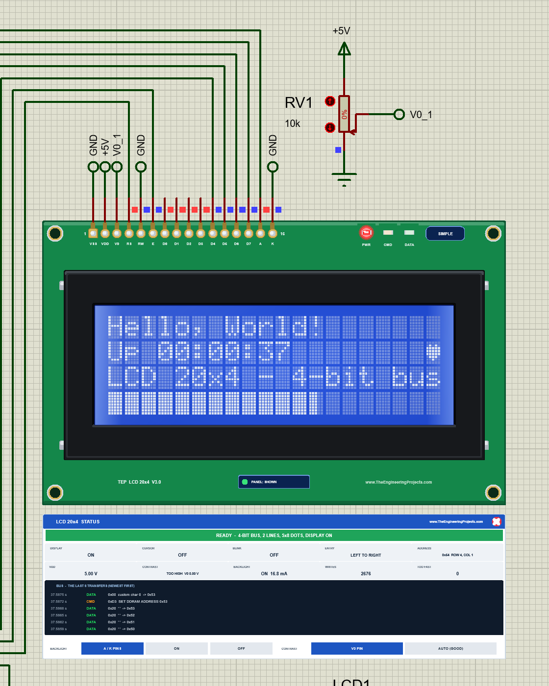
A blank 20x4 at power-on is very often just the contrast: turn the pot until the blocks of rows 1 and 3 just show, then a little back.
Dimming the Backlight with PWM
LCD1's backlight anode A is wired to D10, a PWM pin; the blue backlight takes about 20 mA, which an Arduino pin can drive. The demo's LIGHT command calls analogWrite(), and our model averages the PWM current over 30 ms, as your eye does. LIGHT 60 gives 60 / 255 of the full 16.8 mA:
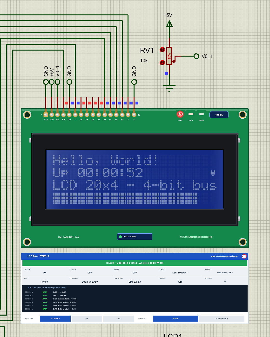
The BACKLIGHT buttons on the panel override the pins for the run: OFF switches the backlight off whatever A does, and ON lights it fully. CONTRAST AUTO (GOOD) ignores V0, which is handy while you have no pot wired yet.
LCD 20x4 Advance: The Pop-Up Window
The Advance LCD keeps only the board on the schematic. Here is LCD2, the yellow-green Advance LCD, after the demo's TEXT3, BAR 75 and BLINK ON commands:
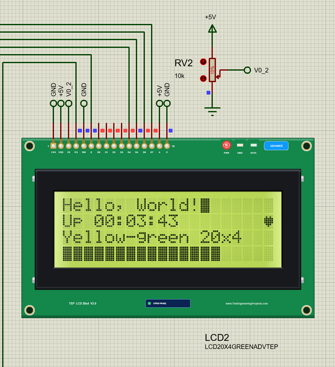
At Run, the "TEP LCD 20x4 Advance" pop-up opens with the look of our TEP Serial Monitor: move it by its header, resize or minimise it, and reopen it with OPEN PANEL. The header has the Display, Bus log and Tests tabs and the theme, Settings and Help icons. Under the header, the BACKLIGHT and CONTRAST buttons work like the Simple panel's.
The Display Page
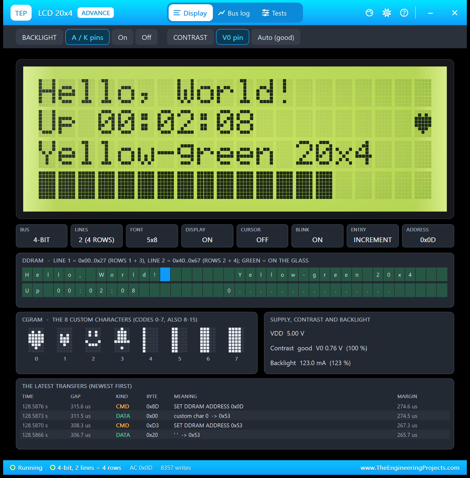
- The glass: a big copy of the LCD, dot by dot, with the backlight and the contrast.
- Tiles: BUS 4-BIT, LINES 2 (4 ROWS), FONT 5x8, DISPLAY ON, CURSOR OFF, BLINK ON, ENTRY INCREMENT and ADDRESS 0x0D, the place right after "Hello, World!" where the demo parks the blinking cursor.
- DDRAM: here you see the row order in memory. Line 1 holds "Hello, World!" in its first 20 cells and "Yellow-green 20x4" in the next 20, so row 3 is simply the second half of line 1. Line 2 holds the clock and then the bar. Green cells are on the glass, the blue cell is the address counter.
- CGRAM: the 8 characters of the demo: two hearts, a smiley, a bell and four bar steps.
- Supply, contrast and backlight: VDD 5.00 V, contrast good V0 0.76 V, backlight 123.0 mA: LCD2's yellow-green backlight is on +5V.
- The latest transfers: the newest bytes with their meaning.
The Bus Log Page
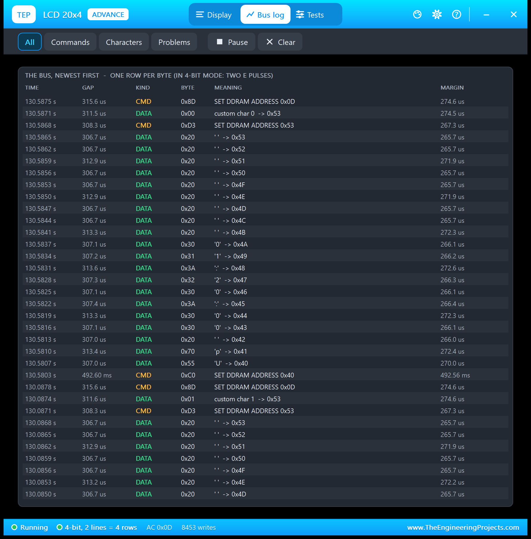
The Bus log keeps the last 512 bytes, newest first, with the time, the gap to the byte before, CMD or DATA, the byte, what it means and the margin: how long after the end of the busy time the byte came. Read the picture from the bottom up: SET DDRAM ADDRESS 0x40 (row 2), then "U", "p", a space and the digits of the clock, the spaces up to 0x53, SET DDRAM ADDRESS 0x53 and the heart in the last cell of row 2, and finally SET DDRAM ADDRESS 0x0D to park the cursor on row 1. With LiquidCrystal on a 16 MHz UNO, every byte comes about 307 us after the one before, far more than the controller needs.
The Tests Page: Four LCD Test Tools
The four tools read the bytes as the model takes them from the bus, the same bytes a real LCD would get. Each has a bold "Good for:" line and a verdict per row: green is fine, amber means check, red means wrong. All the results below come from LCD2 in Proteus 8.5.
1. Init Check: Is lcd.begin() Right?
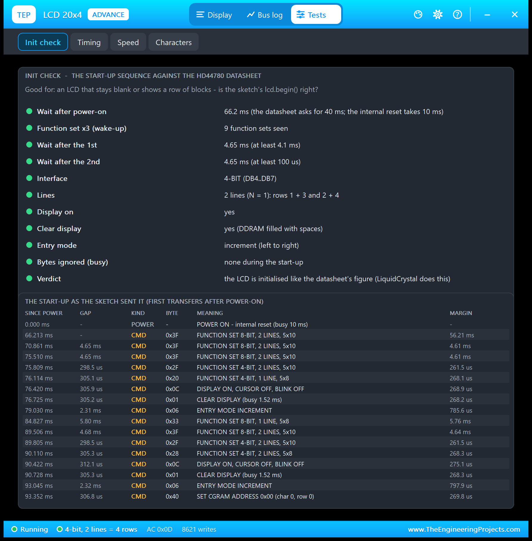
| Check | Result in the picture |
|---|---|
| Wait after power-on | 66.2 ms (the datasheet asks for 40 ms) |
| Function set x3 (wake-up) | 9 function sets seen |
| Wait after the 1st / 2nd | 4.65 ms / 4.65 ms (at least 4.1 ms / 100 us) |
| Interface | 4-BIT (DB4..DB7) |
| Lines | 2 lines (N = 1): rows 1 + 3 and 2 + 4 |
| Display on, clear, entry mode | Yes, yes (DDRAM filled with spaces), increment (left to right) |
| Bytes ignored (busy) | None during the start-up |
| Verdict | The LCD is initialised like the datasheet's figure |
The Lines row matters most on a 20x4: with N = 0 (one line), rows 2 and 4 would stay blank and rows 1 and 3 would show blocks, and the tool would turn red. Why 9 function sets? LiquidCrystal's constructor already starts the LCD once with one line, and then your lcd.begin(20, 4) runs the whole sequence again, now with 2 lines. You can see both runs in the start-up list.
2. Timing: Is the Sketch Too Fast for the Controller?
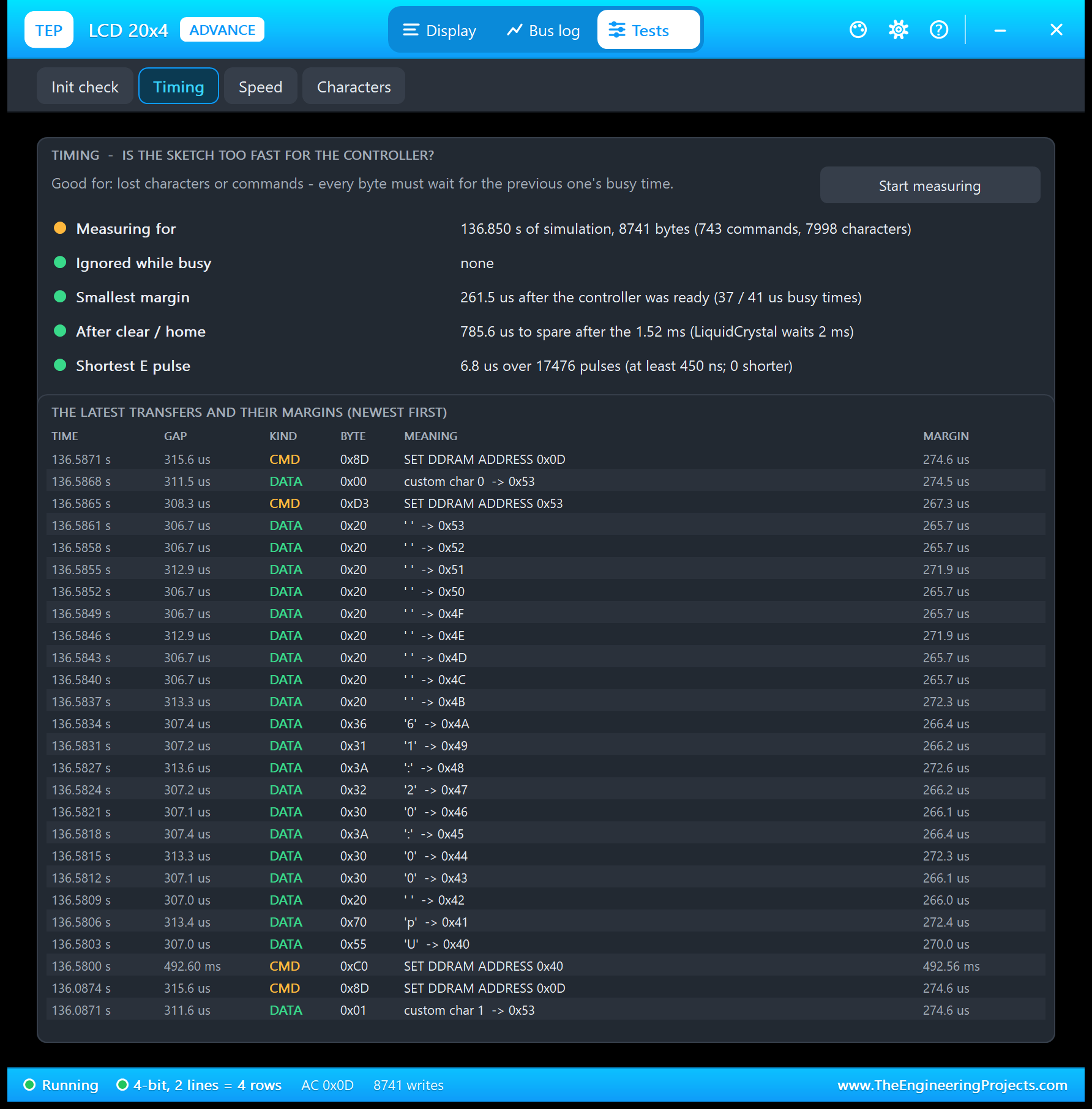
Good for: "lost characters or commands - every byte must wait for the previous one's busy time." The tool counts the bytes, the bytes ignored while busy (none here), the smallest margin after the 37 / 41 us busy times (261.5 us), the margin after a clear or home (785.6 us after the 1.52 ms; LiquidCrystal waits 2 ms), and the shortest E pulse, which must be at least 450 ns: 6.8 us.
3. Speed: How Long Does a 20x4 Screen Take?
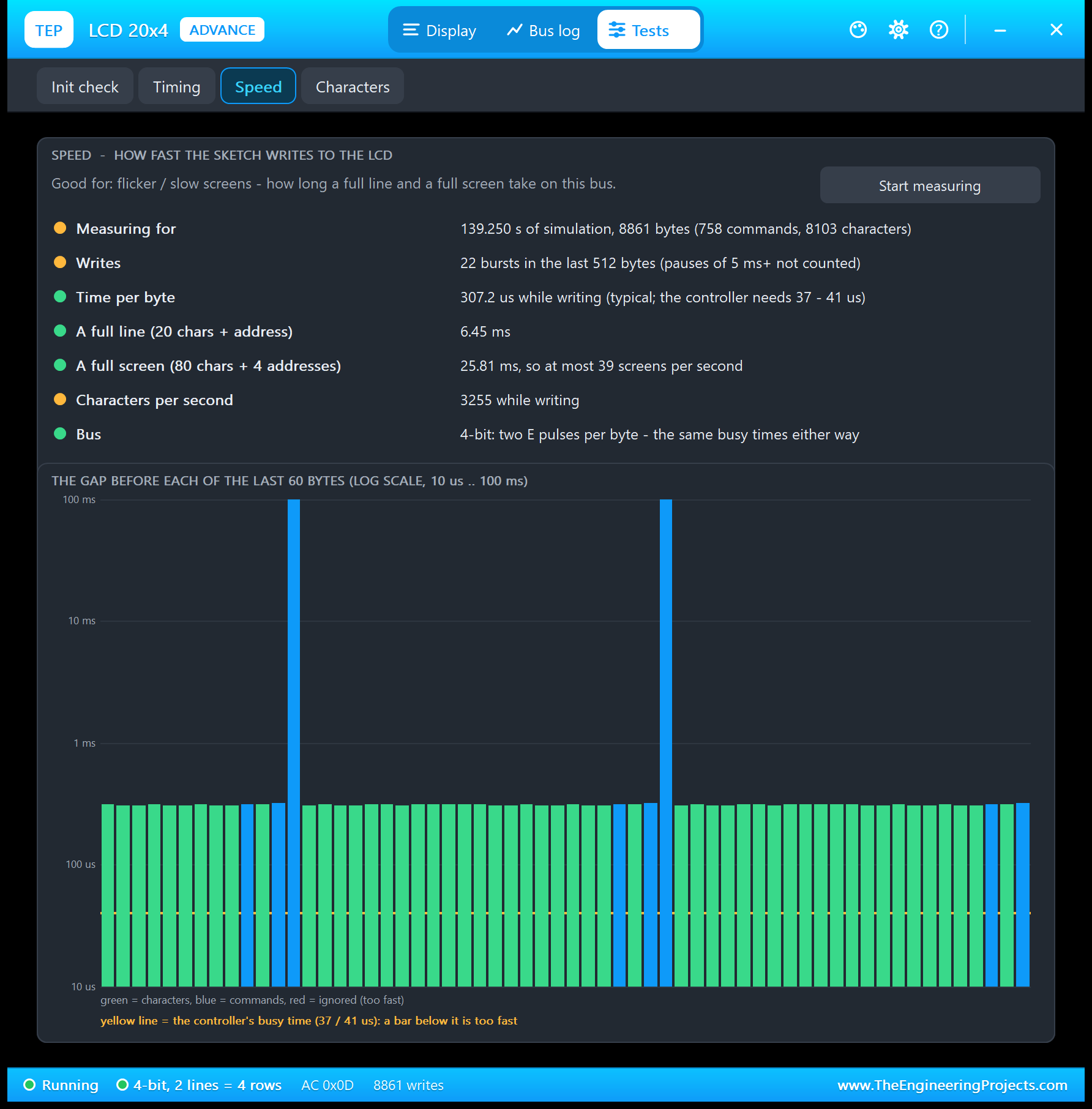
Good for: "flicker / slow screens - how long a full line and a full screen take on this bus." The tool takes the typical gap between two bytes inside a burst of writes; the pauses of the sketch between its writes are not counted. With LiquidCrystal in 4-bit mode on a 16 MHz UNO:
| Result | Value |
|---|---|
| Time per byte | 307.2 us (the controller needs only 37 to 41 us) |
| A full line (20 characters + the address) | 6.45 ms |
| A full screen (80 characters + 4 addresses) | 25.81 ms, so at most 39 screens per second |
| Characters per second | 3255 while writing |
A 20x4 has two and a half times as many characters as a 16x2, so a full rewrite takes 25.81 ms instead of about 10 ms. That is still quick, about five times faster than the same LCD over an I2C backpack (125 ms, see our I2C LCD 20x4 Library for Proteus V1.0), but a sketch that clears and rewrites all four rows in a loop will flicker. Our demo writes only what changed: row 2 twice a second, row 4 only when the bar grows.
4. Characters: Find Any Symbol's Code
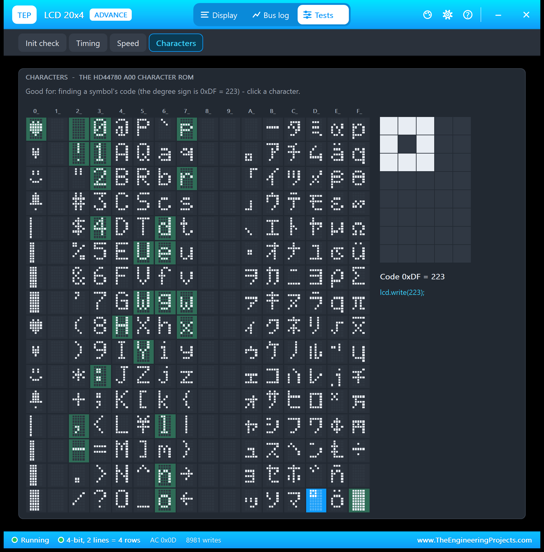
Good for: "finding a symbol's code (the degree sign is 0xDF = 223) - click a character." The map shows all 256 codes in the datasheet's layout, the characters on the glass highlighted. Click one, and it is drawn big with its code and the line to print it, for example lcd.write(223); for a temperature in degrees, and, for one of the 8 own characters, its rows as a byte array for createChar().
LCD 20x4 with Arduino in Proteus
Open LCD-20x4-ArduinoUnoV3.pdsprj from the Proteus Simulation folder, with LCD_20x4_Demo.hex and both DLLs beside it. Its two Arduino UNOs from our Arduino Library for Proteus V3.0 run the same HEX file:
- NODE 1 - SIMPLE (on-sheet panel): UNO 1 (ARD1) with LCD1 (blue, Simple), the contrast pot RV1 and Serial Monitor U1; the backlight on D10 (PWM).
- NODE 2 - ADVANCE (pop-up panel): UNO 2 (ARD2) with LCD2 (yellow-green, Advance), RV2 and Serial Monitor U2; the backlight on +5V, because the yellow-green backlight takes about 120 mA, too much for a pin.
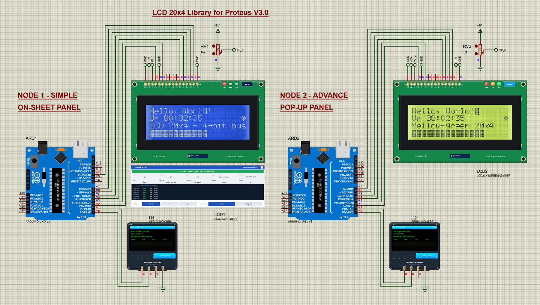
Wiring
| LCD pin | Arduino / supply | Why |
|---|---|---|
| RS, E | D2, D3 | Command or character, and the strobe |
| D4, D5, D6, D7 | D4, D5, D6, D7 | The 4-bit data bus |
| RW, VSS, K | GND | Write only; ground; the backlight's cathode |
| VDD | +5V | Supply |
| V0 | The wiper of a 10k pot between +5V and GND | Contrast |
| A | D10 (PWM) on LCD1, +5V on LCD2 | Backlight |
| Serial Monitor RXD / TXD / GND | Arduino D1 / D0 / ground | Shows what the Arduino prints, sends what you type |
The wiring is exactly that of a 16x2; only lcd.begin() changes. The LCD's header points up, so the power pins reach GND and +5V through short wires with net labels: in Proteus, terminals with the same name are connected, so the V0 pin labelled V0_1 meets the wiper of RV1. The six bus wires come from the UNO without a single crossing (see our Introduction to Arduino UNO for the pins).
The Arduino Code
The demo sketch, LCD_20x4_Demo V3.0, uses Arduino's LiquidCrystal library (version 1.0.7, it comes with the Arduino IDE). The LCD object names the six pins in the order RS, E, D4, D5, D6, D7:
#include <LiquidCrystal.h>

LiquidCrystal lcd(2, 3, 4, 5, 6, 7);   // RS, E, D4, D5, D6, D7
const byte BACKLIGHT_PIN = 10;         // analogWrite(0..255) dims the backlight
In setup(), lcd.begin(20, 4) tells LiquidCrystal the size: it sends the start-up sequence and remembers the four row addresses for setCursor(). Then come the 8 own characters and, after a setCursor() (createChar() leaves the address in CGRAM), the dashboard:
  lcd.begin(20, 4);
  lcd.createChar(HEART_BIG, heartBig);
  lcd.createChar(HEART_SMALL, heartSmall);
lcd.setCursor(0, 0); // createChar leaves the address in CGRAM
redraw();The four rows start with these texts; row 2 shows the clock and row 4 the minute bar instead of a text:
Mode line2 = SHOW_CLOCK;               // line 2: the clock or a text
Mode line4 = SHOW_MINUTE;              // line 4: the minute bar, a bar, the characters or a text
char text[4][21] = {"Hello, World!", "", "LCD 20x4 - 4-bit bus", ""};
To print a row, the sketch moves to the start of that row and pads the text with spaces to 20 characters, so a shorter text never leaves old characters behind, and a text never runs on into the next half of the controller's line, which is two rows further down:
void printLine(byte row, const char* s) {     // the text, padded to 20
  lcd.setCursor(0, row);
  byte n = 0;
  for (; s[n] && n < 20; n++) lcd.print(s[n]);
  for (; n < 20; n++) lcd.print(' ');
}
The clock on row 2 is the up time from millis(), with the heart in the last cell, column 19:
void showClock() {
  unsigned long s = millis() / 1000;
  char buf[21];
  snprintf(buf, sizeof buf, "Up %02lu:%02lu:%02lu", s / 3600 % 100, s / 60 % 60, s % 60);
  printLine(1, buf);
  lcd.setCursor(19, 1);
  lcd.write(byte(beat ? HEART_BIG : HEART_SMALL));
}
Row 4 is the bar: 20 cells of 5 columns give 100 steps, so BAR 37 is exactly 37 columns. A full cell is the ROM's block 0xFF, a part cell one of the four bar characters. The first line of showBar() is the speed trick: if the bar has not changed, nothing is sent at all. The minute bar turns the seconds into steps, so it fills once a minute:
void showBar(int steps) {              // 0..100 steps: 20 cells x 5 columns
  if (steps == shownSteps) return;
  shownSteps = steps;
  lcd.setCursor(0, 3);
  for (byte c = 0; c < 20; c++) {
    int left = steps - c * 5;
    if (left >= 5) lcd.write(byte(0xFF));
    else if (left >= 1) lcd.write(byte(4 + left - 1));
    else lcd.print(' ');
  }
}

void showMinute() {                    // the bar fills once a minute
  unsigned long s = millis() / 1000;
  showBar((s % 60 + 1) * 100 / 60);
}
One command handles all four text rows, TEXT1 to TEXT4; TEXT2 replaces the clock and TEXT4 the bar:
  else if (!strncasecmp(line, "TEXT", 4) && line[4] >= '1' && line[4] <= '4' && !line[5]) {
    byte r = line[4] - '1';
    strncpy(text[r], arg, 20); text[r][20] = 0;
    if (r == 1) line2 = SHOW_TEXT;
    if (r == 3) line4 = SHOW_TEXT;
    printLine(r, text[r]);
The backlight is a PWM pin, so the LIGHT command takes a value from 0 to 255:
  } else if (!strcasecmp(line, "LIGHT")) {
    backlight = constrain(atoi(arg), 0, 255); analogWrite(BACKLIGHT_PIN, backlight);
The loop reads the Serial Monitor and, twice a second, beats the heart and updates the clock and the minute bar. While SCROLL runs, it moves the display one step every 200 ms instead, 20 steps left and 20 back, without delay():
  if (scrollSteps > 0 && now - lastScroll >= 200) {  // SCROLL: the whole display, 20 steps
    lastScroll = now;                                // left (rows 1 and 3 swap places, so
    if (scrollSteps > 20) lcd.scrollDisplayLeft();   // do rows 2 and 4), then 20 back
    else lcd.scrollDisplayRight();
    scrollSteps--;
  }
To change the sketch, export a new HEX file and load it into both UNOs; see How to get the HEX file from Arduino. New to Arduino? Start with our Arduino Tutorial for Beginners.
Serial Monitor Commands
| Command | What it does |
|---|---|
| HELP | The command list |
| STATUS | Lines 1 to 4, the backlight, cursor and blink |
| TEXT1 <text> ... TEXT4 <text> | Row 1 to row 4 (20 characters; a longer text is cut); TEXT2 stops the clock, TEXT4 the bar |
| CLOCK | Row 2 shows the up time with the beating heart again |
| MINUTE | Row 4 shows the bar that fills once a minute again |
| BAR <0-100> | Row 4 shows a bar graph (100 steps) |
| CHARS | Row 4 shows the 8 own characters |
| LIGHT <0-255> | The backlight PWM on D10 |
| CURSOR ON / OFF, BLINK ON / OFF | The underline cursor, the blinking block cursor (after the row 1 text) |
| SCROLL | The display slides 20 steps left and back (rows 1 / 3 and 2 / 4 swap half way) |
| CLEAR | All four rows empty |
How to Run the Demo
- Press Run. Both Serial Monitors (9600 baud) and LCD2's pop-up open; move them aside, as they open over the schematic. The LCDs show the dashboard: "Hello, World!", the clock with the heart, a text and the minute bar.
- Watch the bar on row 4 fill up within a minute and start again.
- Click or hold the arrows on RV1 and watch the contrast and the CONTRAST readout.
- On U1, type LIGHT 60 and LIGHT 255, TEXT3 with your own text, and BAR 37; on U2, SCROLL and watch the rows swap.
- On LCD1's panel, try BACKLIGHT OFF and CONTRAST AUTO (GOOD); close the panel with its red X.
- On LCD2's pop-up, look at the DDRAM grid and the Bus log, and run the four tools.
LCD 20x4 Proteus Simulation Results
The Serial Monitor in Its Simple Interface
Both monitors in this demo run in the Simple interface of our TEP Serial Monitor, as in every monitor screenshot here: only the log, the send box and one slim toolbar row stay visible.
- Switch to it: right-click the log and choose Simple interface, or press Ctrl+Shift+U.
- Back to the full view: click the corner button, press Esc or Ctrl+Shift+U, or right-click and choose Full interface.
- Your choice is remembered.
Type a command in the send box and press Enter. Every line the demo prints is 80 characters or less. Read all about the monitor in TEP Serial Monitor Advance for Proteus.
U1: HELP and STATUS
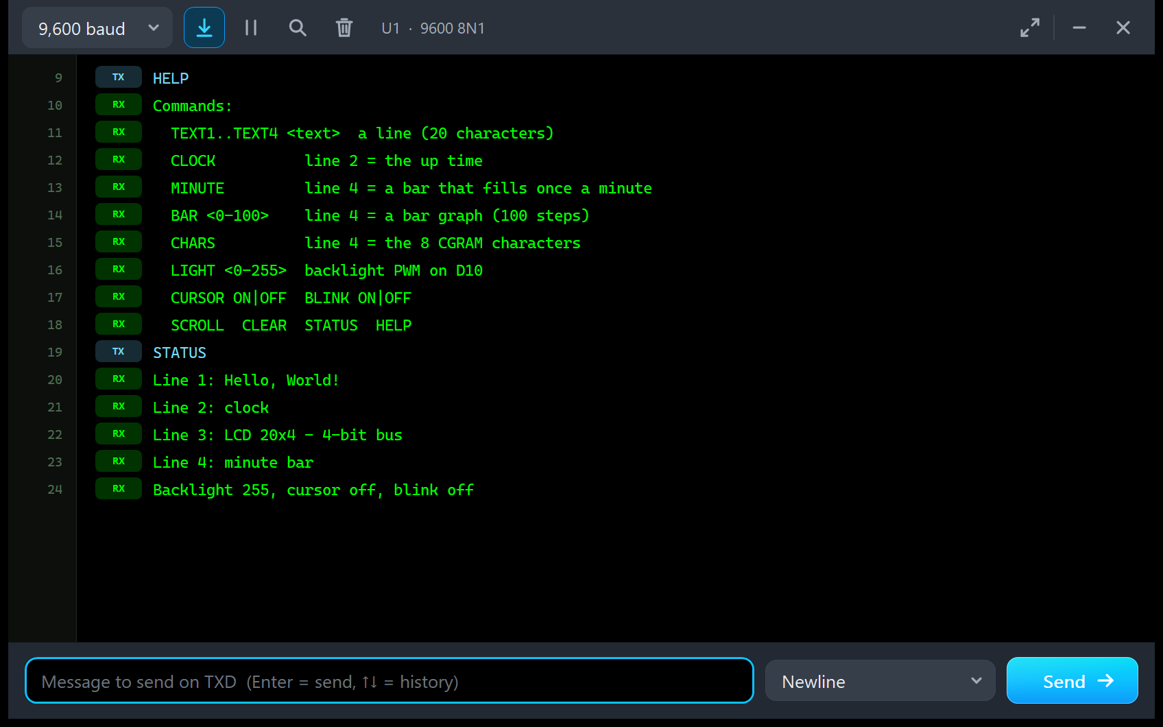
HELP
Commands:
  TEXT1..TEXT4 <text>  a line (20 characters)
  CLOCK          line 2 = the up time
  MINUTE         line 4 = a bar that fills once a minute
  BAR <0-100>    line 4 = a bar graph (100 steps)
  CHARS          line 4 = the 8 CGRAM characters
  LIGHT <0-255>  backlight PWM on D10
  CURSOR ON|OFF  BLINK ON|OFF
  SCROLL  CLEAR  STATUS  HELP
STATUS
Line 1: Hello, World!
Line 2: clock
Line 3: LCD 20x4 - 4-bit bus
Line 4: minute bar
Backlight 255, cursor off, blink off
In the sketch's own words, "line" means a row of the screen here. At the start the sketch prints "LCD 20x4 V3.0 demo - The Engineering Projects" and "Type HELP for the commands".
U2: BAR, TEXT3, BLINK and STATUS
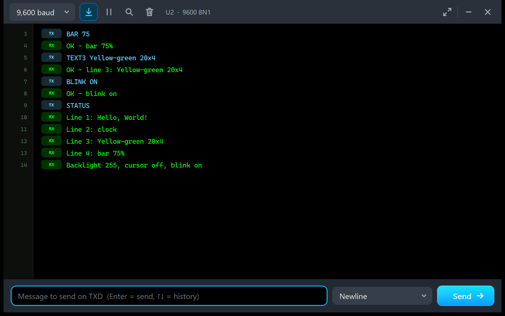
BAR 75
OK - bar 75%
TEXT3 Yellow-green 20x4
OK - line 3: Yellow-green 20x4
BLINK ON
OK - blink on
STATUS
Line 1: Hello, World!
Line 2: clock
Line 3: Yellow-green 20x4
Line 4: bar 75%
Backlight 255, cursor off, blink on
BAR 75 draws 15 full cells on row 4, and BLINK ON parks the blinking block cursor right after "Hello, World!": the LCD2 picture and the Display page above show the result on the yellow-green glass.
Troubleshooting
- The glass stays dark and the PWR LED is off: no power. Check VDD and VSS (the panel says NO POWER with the voltage).
- Blocks on rows 1 and 3: the sketch did not initialise the LCD. Check the pins in
LiquidCrystal lcd(...)and the wires to RS, E and D4 to D7 (on the Advance, run the Init check). - Text from row 1 goes on in row 3: that is the 20x4's row order. Print every row after its own setCursor(0, row), and keep each text to 20 characters.
- Rows 3 and 4 never show what you print: the sketch calls lcd.begin(16, 2); give it lcd.begin(20, 4).
- Characters missing or wrong: bytes sent while the controller was busy (the panel's TOO FAST readout, the red lines in the bus log, the Timing tool).
- Faint characters or blocks behind them: the contrast. Turn the pot, or set CONTRAST AUTO (GOOD).
- The part is not simulated, or no monitor window: TEPLCD.DLL or TEPSERIALMON.DLL is missing from MODELS and the project folder (or an older TEPLCD.DLL without the LCD 20x4 devices is there); click OPEN MONITOR on a closed monitor.
- The Advance pop-up does not appear: click OPEN PANEL on the board, or turn "Open the panel at Run" back on in Settings.
Things to Know Before Using a Real 20x4 LCD
The demo sketch uses only LiquidCrystal and Serial, so it runs on a real UNO and 20x4 LCD too. Keep in mind:
- Contrast first: a blank LCD at power-on is very often just the contrast. Turn the pot until the blocks of rows 1 and 3 just show, then a little back.
- Tell the library the size:
lcd.begin(20, 4), and print every row after its own setCursor(). - The backlight: most blue 2004 boards have a backlight resistor on the board; some yellow-green boards have none and take far more current, so check your board's datasheet. The blue one is fine on a PWM pin, the yellow-green one needs a transistor.
- Pins: the 4-bit bus takes six Arduino pins; if you need them for something else, the same LCD with an I2C backpack takes only two (see our I2C LCD 20x4 Library for Proteus V1.0).
- Speed: about 26 ms for the whole screen, so update only what changed.
Limitations of the Simulation
- Not modelled: the 5x10 font on the glass (the setting is taken and shown, the characters are drawn 5x8), temperature, the slow response of the liquid crystal (the glass changes at once), the A02 (European) ROM, the LCD's current draw on VDD and the viewing angle.
- The PWR, CMD and DATA LEDs, the badge, the panel button, the STATUS panel and the pop-up are TEP additions; a real board has only its backlight.
- The model is our own implementation, written from the HD44780 datasheet; HD44780 is a Hitachi part, and this library is not made or endorsed by Hitachi or by Labcenter.
- Licences: the demo sketch uses Arduino's LiquidCrystal 1.0.7. The HEX file contains it and the Arduino AVR core 1.8.6, which include LGPL-licensed code; their source code is on GitHub.
- Tested in Proteus 8.5 in October 2026 (the demo as shipped, both LCDs, the dashboard, the commands, SCROLL, the pots, the backlight PWM, the panel, the pop-up, the four tools and every screenshot here; about 0.6 x real time with the pop-up and both monitors open; our LCD 16x2 V3.0, I2C LCD 16x2 V1.0 and I2C LCD 20x4 V1.0 demos run unchanged on the same DLL) and with automatic PC checks, 0 failed: 49 with the real 20x4 demo sketch and LiquidCrystal against the model, 7,202 on the HD44780 controller, and the demo project read back from disk. Proteus 7 is not supported.
So, that was all about the LCD 20x4 Library for Proteus V3.0. I hope the real row order, the contrast pot, the backlight and the test tools make the big character LCD much easier to understand, so your 20x4 works the first time you wire a real one. If you use the LCD 20x4 Library for Proteus in a project, please share your feedback in the comments or in our forum, and if you have any questions, ask in the comments and I will help you out. Till the next tutorial, take care and have fun!
Comments
0