


MFRC522 RFID Proteus Library | RC522 Arduino Simulation


Hello friends, I hope you are doing well. In today's tutorial, I am going to share our MFRC522 RFID Proteus Library. With this library, we can connect an RC522 RFID reader to an Arduino Uno and place a virtual card on the reader with a single click. The Arduino reads the card's UID and stored data, and then prints whether access is granted or denied.
We will start with the basics of the reader and its cards, install the library files and wire the SPI pins. After that, we will run the supplied simulation, understand the Arduino code and work through the numbers shown on the Virtual Terminal. The download includes the wired project, compiled HEX, editable sketch and the Arduino driver, so you can run the example before compiling anything yourself.
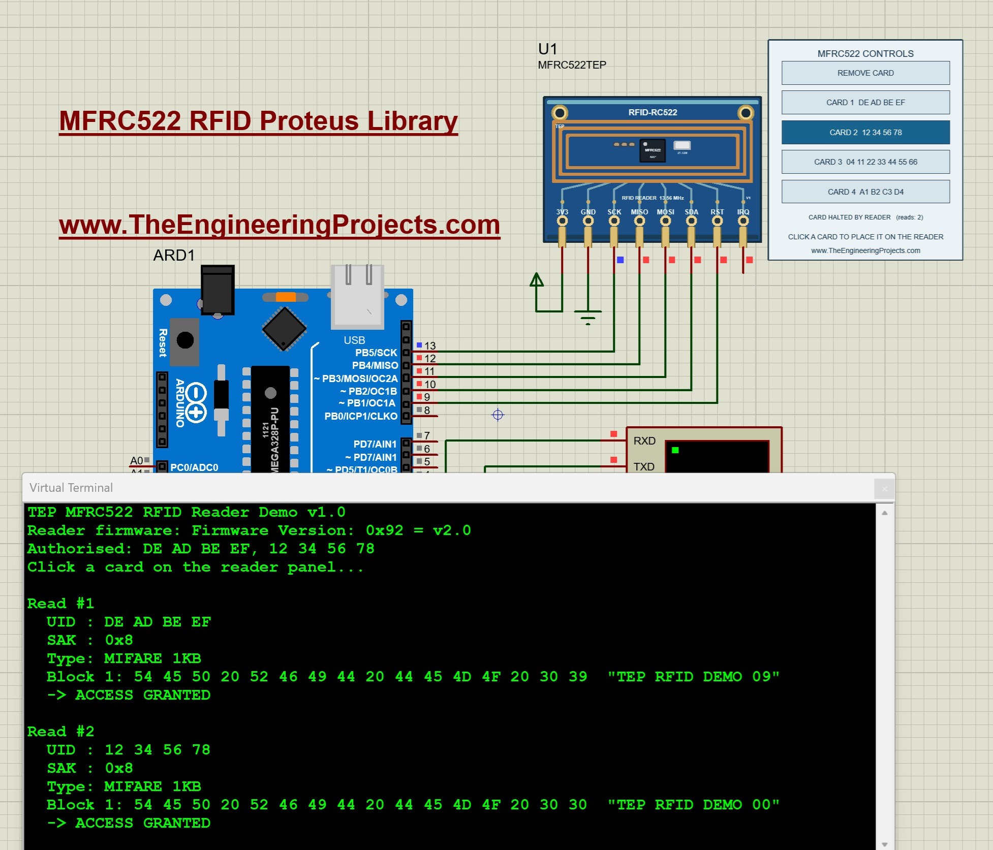
This tutorial uses our V1.0 package, the TEP Arduino UNO V3 and a 16 MHz clock. The package targets Proteus 8.5 with AVR simulation support. In the running screenshot below, two cards have been placed on the reader one after the other. Both belong to the authorised list, so both show ACCESS GRANTED.
What Is the MFRC522 RFID Reader?
The MFRC522 is a reader IC from NXP for contactless cards that work at 13.56 MHz. The popular blue board built around this chip is sold as the RC522 module. It reads and writes cards that follow the ISO/IEC 14443 A standard, which includes the MIFARE family. The Arduino controls the reader through SPI, and the chip's registers and commands are described in NXP's MFRC522 datasheet.
If you want more background on the hardware, read our Introduction to MFRC522 and Interfacing of RFID RC522 with Arduino tutorials. In this tutorial, we will work with the simulation.
How the Reader Reads a Card
A card has no battery. It takes its power from the reader's field and answers the reader's commands. The exchange follows a fixed sequence:
- Request: the reader sends a request command called REQA. A card in the field answers with two bytes called ATQA.
- Anticollision: the reader asks for the card's serial number, and the card sends its UID.
- Select: the reader selects that UID. The card confirms with one byte called SAK, which identifies the card type.
- Authenticate: for a MIFARE Classic card, the reader proves that it knows the key of a memory sector.
- Read or write: the reader exchanges data blocks with the card.
- Halt: the reader puts the card to sleep, so it does not answer again until it is presented once more.
Important Terms
- UID: the unique identifier of the card. It has 4 bytes on a MIFARE Classic 1K card and 7 bytes on a MIFARE Ultralight card.
- SAK: the select acknowledge byte. The driver uses it to find the card type.
- Block: a group of 16 bytes in a MIFARE Classic card's memory.
- Sector: a group of four blocks that share the same keys.
- Key A and Key B: two 6-byte keys that protect each sector.
Features of Our Proteus Model
- The component is named MFRC522TEP and has eight pins, as on the hardware module.
- Four virtual cards are available on a control panel beside the reader.
- Three cards are MIFARE Classic 1K cards, and one is a MIFARE Ultralight card.
- Each card's UID and the two keys can be changed in the component properties.
- The Arduino communicates with the model through real SPI commands and registers.
Keep one distinction in mind. This is a functional model of the chip and its cards. A click on the panel replaces the physical action of bringing a card near the antenna. The radio field, reading distance and antenna tuning are not simulated.
Download the MFRC522 RFID Library for Proteus
First of all, download the V1.0 package using the button below. Extract the complete ZIP into a normal folder before opening the project, and keep the files of the simulation folder together.
Download MFRC522 RFID Proteus Library V1.0 and Arduino Simulation| Folder or file | Contents and purpose |
|---|---|
| Proteus Library Files | TEPMFRC522.LIB for the reader, and the TEP Arduino UNO V3 LIB/IDX files. |
| Proteus Model Files | TEPMFRC522.DLL, which provides the reader's simulated behavior. |
| Proteus Simulation | MFRC522-ArduinoUnoV3.pdsprj, MFRC522_Demo.hex and a local copy of the DLL. |
| Arduino Code | The sketch, the MFRC522 1.4.12 driver, the AVR core archive and a firmware rebuild script. |
| Model Source | The chip and card model, SPI transport and Proteus adapter. |
| Documentation | Model notes, third-party notices and a preview of the board artwork. |
| README.txt and SHA256SUMS.txt | Quick-start instructions and checksums of the packaged files. |
The Proteus library and the Arduino library have different jobs. The LIB file defines the component that we place on the schematic, and the DLL gives it its behavior. The MFRC522 Arduino library gives our sketch the functions for talking to the reader. Installing the Arduino library alone will not make MFRC522TEP appear in Proteus.
How to Install the MFRC522 Library in Proteus
Copy the Library and Model Files
Save your work and close Proteus before copying the files. Then follow these steps:
- Open the extracted Proteus Library Files folder.
- Copy
TEPMFRC522.LIBinto the library directory configured for your Proteus installation. - Copy
ArduinoV3TEP.LIBandArduinoV3TEP.IDXfrom the same folder if our TEP Arduino UNO V3 library is not installed already. - Open Proteus Model Files and copy
TEPMFRC522.DLLinto your configured ProteusMODELSdirectory. - Restart Proteus, open Pick Devices and search for MFRC522TEP.
- Place the reader on the schematic, or open the supplied project to use the completed circuit.
Points to Remember
- Use the library and model folders that your installation actually searches. Their locations differ between installations.
- The reader is supplied as a LIB file without a separate IDX. The included IDX belongs to the Arduino board.
- Keep the extra DLL beside the project in the Proteus Simulation folder.
- MFRC522_Demo.hex belongs to the Arduino's Program File property. The reader does not need a HEX file.
- Compatibility with Proteus 7 has not been established.
The Arduino board in this project comes from our Arduino Library for Proteus V3.0. Start with the supplied project, so that the board, wiring and firmware match the demonstration.
MFRC522 Pinout and Arduino Uno Wiring
The TEP reader has eight pins along its lower edge. From left to right, they are 3V3, GND, SCK, MISO, MOSI, SDA, RST and IRQ. Start each wire at the exposed pin endpoint below the board artwork.
| Reader pin | Connection | Purpose |
|---|---|---|
| 3V3 | Positive supply terminal | Powers the digital model. |
| GND | Ground | Provides the shared reference. |
| SCK | Arduino Uno D13 | SPI clock from the Arduino. |
| MISO | Arduino Uno D12 | Data from the reader to the Arduino. |
| MOSI | Arduino Uno D11 | Data from the Arduino to the reader. |
| SDA | Arduino Uno D10 | SPI chip select. It is active low. |
| RST | Arduino Uno D9 | Reset input. A low level resets the reader. |
| IRQ | Unconnected | Interrupt output. The supplied sketch does not use it. |
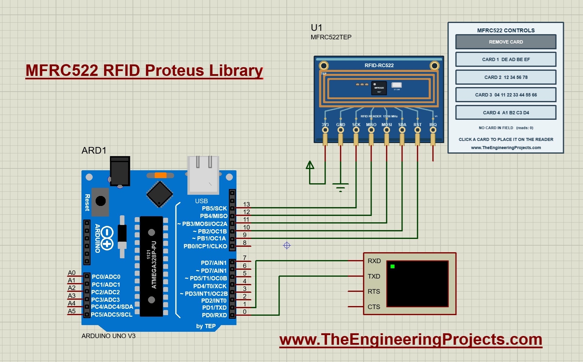
The pin named SDA can be confusing, because SDA is also the name of the I2C data line. On this module in SPI mode, SDA works as the chip select pin. The sketch calls it SS_PIN.
Virtual Terminal Connections
- Connect Arduino D1/TX to RXD on the Virtual Terminal.
- Set the terminal to 9600 baud, eight data bits, no parity and one stop bit.
- The return connection to D0/RX is shown in the circuit, but this sketch does not read typed commands.
Notes for Physical Hardware
- Power a real RC522 module from 3.3 V. Connecting its supply pin to 5 V can damage it.
- The model only checks that 3V3 is high and GND is low. It does not check the supply voltage.
- The MFRC522 is a 3.3 V device, so check the logic levels required by your board before connecting a 5 V Arduino.
- Follow the labels printed on your module. Its header order can differ from the order of our Proteus board.
Run the MFRC522 Simulation
Start the Simulation
- Open
Proteus Simulation/MFRC522-ArduinoUnoV3.pdsprjfrom the extracted package. - Keep
MFRC522_Demo.hexandTEPMFRC522.DLLin that folder. - Double-click the Arduino and confirm that its Program File is MFRC522_Demo.hex.
- Confirm the 16 MHz clock and the 9600 baud terminal.
- Press Run and open the Virtual Terminal window if it is hidden.
The terminal prints the demo heading, the reader's version and the two authorised UIDs. The version line reads Firmware Version: 0x92 = v2.0. It shows that the Arduino has read the reader's version register correctly through SPI. The last line asks you to click a card.
Place a Card on the Reader
- Click CARD 1 on the control panel. The row turns blue.
- Read the new lines on the terminal.
- Click CARD 2 and compare the result.
- Try CARD 3 and CARD 4, which are not in the authorised list.
- Click REMOVE CARD to take the card out of the field.
The running screenshot at the top shows the first two steps. Read #1 reports UID DE AD BE EF, SAK 0x8 and the type MIFARE 1KB. Its block 1 contains the text "TEP RFID DEMO 09", and the result is ACCESS GRANTED. Read #2 reports UID 12 34 56 78 with the text "TEP RFID DEMO 00", and access is granted again.
Default Cards of the Library
| Card | UID | Card type | SAK | Result |
|---|---|---|---|---|
| CARD 1 | DE AD BE EF | MIFARE Classic 1K | 0x08 | ACCESS GRANTED |
| CARD 2 | 12 34 56 78 | MIFARE Classic 1K | 0x08 | ACCESS GRANTED |
| CARD 3 | 04 11 22 33 44 55 66 | MIFARE Ultralight | 0x00 | ACCESS DENIED |
| CARD 4 | A1 B2 C3 D4 | MIFARE Classic 1K | 0x08 | ACCESS DENIED |
The terminal prints the SAK as 0x8 instead of 0x08. The Arduino print function does not add a leading zero to a hexadecimal number. For CARD 3, the sketch prints the UID, SAK and type only, because the block reading part is written for MIFARE Classic cards.
Understand the MFRC522 Control Panel
The panel beside the reader has five buttons and a status line. It is active while the simulation runs.
- REMOVE CARD takes the card out of the reader's field.
- CARD 1 to CARD 4 place that card in the field. Each button shows the card's UID.
- The status line shows what the reader has done with the card.
- The reads counter counts how many times the reader has selected a card.
| Status | Meaning |
|---|---|
| NO CARD IN FIELD | No card is placed on the reader. |
| CARD IDLE - WAITING FOR REQA | A card is present, but the reader has not requested it yet. |
| CARD ANSWERED REQA | The card has answered the request and waits to be selected. |
| CARD SELECTED BY READER | The reader has selected the card and can exchange data with it. |
| CARD HALTED BY READER | The sketch has finished and put the card to sleep. |
Why Each Click Gives One Read
In the screenshot, the status line shows CARD HALTED BY READER with two reads. The sketch halts every card after reading it. A halted card ignores the normal request command, so the same card is not read again and again while it stays on the reader. Click the same card once more to present it again. The Simulation Log also records every card that is placed or removed.
Arduino Code for the MFRC522 Simulation
The following is the exact sketch included in the download. It uses the bundled MFRC522 Arduino library, version 1.4.12. Use the supplied copy for your first build, so that your firmware matches the packaged HEX file.
/*
  MFRC522 RFID Reader - Arduino UNO demo for the TEP Proteus library
  The Engineering Projects - www.TheEngineeringProjects.com

  Wiring (as in MFRC522-ArduinoUnoV3.pdsprj):
    3V3 -> 5V (simulation)   GND -> GND
    SCK -> D13   MISO -> D12   MOSI -> D11   SDA (SS) -> D10   RST -> D9   IRQ -> not used
    Arduino D1/TX -> Virtual Terminal RXD (9600 8N1)

  Uses the standard "MFRC522" library by GithubCommunity (miguelbalboa), v1.4.x.
  In the simulation click CARD 1..4 on the reader panel to place a card.
  Cards 1 and 2 are authorised; cards 3 and 4 are denied.
*/
#include <Arduino.h>
#include <SPI.h>
#include <MFRC522.h>

#define SS_PIN  10
#define RST_PIN 9

MFRC522 rfid(SS_PIN, RST_PIN);
MFRC522::MIFARE_Key key;

const byte authorised[][4] = { {0xDE, 0xAD, 0xBE, 0xEF}, {0x12, 0x34, 0x56, 0x78} };
const byte AUTH_COUNT = sizeof(authorised) / sizeof(authorised[0]);
unsigned long readCount = 0;

void printHex(const byte* data, byte length) {
  for (byte i = 0; i < length; i++) {
    if (data[i] < 0x10) Serial.print('0');
    Serial.print(data[i], HEX);
    if (i + 1 < length) Serial.print(' ');
  }
}

bool isAuthorised(const MFRC522::Uid& uid) {
  if (uid.size != 4) return false;
  for (byte i = 0; i < AUTH_COUNT; i++)
    if (memcmp(uid.uidByte, authorised[i], 4) == 0) return true;
  return false;
}

void setup() {
  Serial.begin(9600);
  SPI.begin();
  rfid.PCD_Init();
  for (byte i = 0; i < 6; i++) key.keyByte[i] = 0xFF;   // factory default key

  Serial.println(F("TEP MFRC522 RFID Reader Demo v1.0"));
  Serial.print(F("Reader firmware: "));
  rfid.PCD_DumpVersionToSerial();
  Serial.println(F("Authorised: DE AD BE EF, 12 34 56 78"));
  Serial.println(F("Click a card on the reader panel..."));
}

void loop() {
  if (!rfid.PICC_IsNewCardPresent()) return;   // REQA every loop; a card answers once placed
  if (!rfid.PICC_ReadCardSerial()) return;     // anticollision + select

  readCount++;
  Serial.println();
  Serial.print(F("Read #")); Serial.println(readCount);
  Serial.print(F("  UID : ")); printHex(rfid.uid.uidByte, rfid.uid.size); Serial.println();
  Serial.print(F("  SAK : 0x")); Serial.println(rfid.uid.sak, HEX);
  MFRC522::PICC_Type type = rfid.PICC_GetType(rfid.uid.sak);
  Serial.print(F("  Type: ")); Serial.println(rfid.PICC_GetTypeName(type));

  // MIFARE Classic: authenticate sector 0 and read block 1 (the demo text)
  if (type == MFRC522::PICC_TYPE_MIFARE_1K || type == MFRC522::PICC_TYPE_MIFARE_4K || type == MFRC522::PICC_TYPE_MIFARE_MINI) {
    MFRC522::StatusCode status = rfid.PCD_Authenticate(MFRC522::PICC_CMD_MF_AUTH_KEY_A, 1, &key, &rfid.uid);
    if (status == MFRC522::STATUS_OK) {
      byte buffer[18]; byte size = sizeof(buffer);
      status = rfid.MIFARE_Read(1, buffer, &size);
      if (status == MFRC522::STATUS_OK) {
        Serial.print(F("  Block 1: ")); printHex(buffer, 16);
        Serial.print(F("  \"")); for (byte i = 0; i < 16; i++) Serial.print(buffer[i] >= 32 && buffer[i] < 127 ? (char)buffer[i] : '.'); Serial.println('"');
      } else { Serial.print(F("  MIFARE_Read failed: ")); Serial.println(rfid.GetStatusCodeName(status)); }
    } else { Serial.print(F("  Authentication failed: ")); Serial.println(rfid.GetStatusCodeName(status)); }
  }

  Serial.println(isAuthorised(rfid.uid) ? F("  -> ACCESS GRANTED") : F("  -> ACCESS DENIED"));

  rfid.PICC_HaltA();        // card stays silent until it is removed and placed again
  rfid.PCD_StopCrypto1();
}
Set the Pins and the Authorised List
SS_PINis 10 andRST_PINis 9. They match the SDA and RST connections of our circuit.- The SPI pins D11, D12 and D13 are fixed by the Arduino Uno hardware, so the sketch does not name them.
- The array
authorisedholds the two UIDs that are allowed. AUTH_COUNTis calculated from the array size. If you add a third UID, the count follows automatically.
The function printHex prints each byte as two hexadecimal characters and adds a leading zero when the value is below 0x10. The function isAuthorised accepts only 4-byte UIDs and compares them with the list. A 7-byte UID is therefore always denied by this sketch.
Initialize the Reader
In setup, the sketch starts the serial port and SPI, and then calls rfid.PCD_Init(). In this driver version, the function does the following work:
- It resets the reader.
- It sets a timeout of 25 ms for card communication.
- It selects the modulation and the CRC preset required by the card standard.
- It switches the antenna driver on.
The loop after that fills all six key bytes with 0xFF. This is the factory default key of MIFARE Classic cards, and it is also the default key of the cards in our model. Finally, PCD_DumpVersionToSerial() reads the version register and prints it.
Detect and Select a Card
The loop begins with two checks. PICC_IsNewCardPresent() sends the request command and returns true when a card answers. PICC_ReadCardSerial() performs the anticollision and select steps. If either function fails, the loop returns and tries again.
After a successful selection, the UID, its size and the SAK are stored in rfid.uid. The sketch prints them, and PICC_GetType() converts the SAK into a card type. A SAK of 0x08 means MIFARE Classic 1K, and the driver's name for it is MIFARE 1KB.
Authenticate and Read Block 1
A MIFARE Classic card does not give its data to every reader. The call PCD_Authenticate() uses Key A on block 1. When it succeeds, the whole sector of that block is open for reading.
The call MIFARE_Read(1, buffer, &size) reads block 1. The buffer has 18 bytes, although a block has 16 bytes. The card adds a 2-byte CRC to its answer, and the driver rejects a smaller buffer. The sketch prints the 16 data bytes in hexadecimal and then as text.
Decide Access and Halt the Card
The access decision depends on the UID only. The sketch prints ACCESS GRANTED when the UID is in the list, and ACCESS DENIED otherwise. After that, PICC_HaltA() puts the card to sleep and PCD_StopCrypto1() ends the authenticated state of the reader. Without the second call, the reader cannot start a new communication.
Understand the Card Memory and Calculations
MIFARE Classic 1K Memory Layout
Each Classic card in our model has the complete memory of a 1K card. The size follows from its structure:
16 sectors × 4 blocks × 16 bytes = 1024 bytes
- Block 0 holds the UID, a check byte, the SAK, the ATQA and manufacturer data. It is read-only.
- Block 1 holds the demo text of our model.
- The last block of every sector is the sector trailer. It holds Key A, the access bits and Key B.
- The default access bits in the model are FF 07 80 69.
- Key A is never returned by a read. The card sends zeros in its place.
How many bytes remain for our own data? The 16 sector trailers use 16 × 16 = 256 bytes, and block 0 uses 16 bytes. That leaves 1024 - 256 - 16 = 752 bytes.
Find the Sector of a Block
The sector number is block number / 4, without the remainder. Block 1 belongs to sector 0, and block 9 belongs to sector 2. The trailer of a sector is at 4 × sector + 3. For sector 0, the trailer is block 3. This is why authenticating block 1 also opens blocks 0 and 2.
Calculate the Check Byte of the UID
The fifth byte of block 0 is a check byte called BCC. It is the exclusive OR of the four UID bytes. For CARD 1, the calculation is:
- DE XOR AD = 73
- 73 XOR BE = CD
- CD XOR EF = 22
The BCC of CARD 1 is therefore 0x22. For CARD 2, the same steps give 12 XOR 34 XOR 56 XOR 78 = 0x08. The reader uses this byte to check that it received the UID correctly.
Decode the Text of Block 1
The terminal prints block 1 as 16 hexadecimal bytes. Each byte is the ASCII code of one character.
| Bytes | Text |
|---|---|
| 54 45 50 | TEP |
| 20 | Space |
| 52 46 49 44 | RFID |
| 20 | Space |
| 44 45 4D 4F | DEMO |
| 20 | Space |
| 30 39 | 09 |
Why does CARD 1 end with 09 and CARD 2 with 00? The model sets the last character from the last UID byte. It takes the remainder of that byte divided by 10:
- CARD 1: the last byte is 0xEF, which is 239. The remainder is 9, so the text ends with 09.
- CARD 2: the last byte is 0x78, which is 120. The remainder is 0, so the text ends with 00.
- CARD 4: the last byte is 0xD4, which is 212. The remainder is 2, so the text ends with 02.
Calculate the Reader's Timeout
The driver programs the reader's timer with a prescaler value of 169 and a reload value of 1000. The timer frequency is:
13.56 MHz / (2 × 169 + 1) = 13.56 MHz / 339 = 40 kHz
One timer step is therefore 25 microseconds, and 1000 steps give 25 ms. If no card answers within this time, the driver reports a timeout. The model raises the timeout flag immediately when nothing answers, so you do not see this delay in the simulation.
Change the Cards and Keys
Edit the Component Properties
Stop the simulation and double-click the reader to open its properties.
- UID1 to UID4 set the four cards. Eight hexadecimal characters create a MIFARE Classic 1K card, and 14 characters create a MIFARE Ultralight card.
- KEYA and KEYB set the keys of the Classic cards. Each key has 12 hexadecimal characters, and the default is FFFFFFFFFFFF.
- An invalid UID is replaced by the default UID of that card.
Data written to a card remains while the simulation runs. When the simulation restarts, every card returns to its default contents.
Experiments to Try
Change one thing at a time and predict the result before you press Run. The results below follow from the sketch and the model's rules.
| Change | Expected result |
|---|---|
| Click CARD 4. | The text ends with 02 and the result is ACCESS DENIED. |
| Click CARD 3. | A 7-byte UID and SAK 0x0 are printed, without a block line, and access is denied. |
| Add A1 B2 C3 D4 to the authorised array and rebuild. | CARD 4 is granted. |
| Set UID1 to CAFE0001. | CARD 1 is denied, because its new UID is not in the list. |
| Set KEYA to A0A1A2A3A4A5. | The sketch prints Authentication failed: Timeout in communication. |
| Click the same card twice. | Two separate reads are printed and the reads counter increases by two. |
The key experiment shows an important detail. With a wrong key, the sketch cannot read block 1, but it still prints ACCESS GRANTED for an authorised UID. The decision in this demonstration does not depend on the authentication result.
Compile and Load Your Own Arduino Changes
- Open
Arduino Code/MFRC522_Demo/MFRC522_Demo.inoin Arduino IDE. - Install the MFRC522 library. For the same version as the example, copy
Arduino Code/libraries/MFRC522into your sketchbook's libraries folder. - Select Arduino Uno as the board.
- Compile the sketch and use the Export Compiled Binary command.
- Select the new application HEX in the Arduino's Program File property.
- Restart the simulation.
The package also contains a rebuild script and the AVR core source archive. Its README explains the compiler folders required for that route. Editing the INO file alone does not change the firmware that Proteus has loaded.
Common Problems and Their Solutions
| Problem | What to check |
|---|---|
| MFRC522TEP is missing from Pick Devices. | Check that TEPMFRC522.LIB is in the active library folder and restart Proteus. |
| The reader is placed, but its model cannot load. | Check TEPMFRC522.DLL in MODELS and beside the project. |
| The terminal prints a communication failure warning. | Check SCK, MISO, MOSI and SDA, then 3V3 and GND. |
| The version is not 0x92. | The SPI connection is not working. Check the wiring and the chip select pin. |
| A card is not detected. | Click inside a card row while the simulation runs, and check the Simulation Log. |
| The same card is not read again. | The card is halted. Click it again or remove it first. |
| The terminal is blank or unreadable. | Check the Program File, the 16 MHz clock, D1/TX to RXD and 9600 baud. |
| Code changes have no effect. | Compile a new HEX and select it in the Arduino before restarting. |
If a problem remains, return to the unmodified project and change one thing at a time. When you ask for help, mention which card you clicked and include the terminal output.
Practical Review and Model Limitations
This library is useful for learning the complete sequence of a card read, from the request to the halt. The panel shows the state of the card at each stage, and the editable UIDs let us test both granted and denied cases. According to the package notes, the model was tested on a PC with the unmodified Arduino driver, including authentication, block reads and writes, and both UID lengths.
What the Model Supports
- The reader's registers, 64-byte FIFO, CRC calculation and interrupt flags through SPI.
- Request, anticollision, select and halt for 4-byte and 7-byte UIDs.
- MIFARE Classic authentication, read, write and value-block commands.
- MIFARE Ultralight page read and write.
What the Model Does Not Simulate
- The radio field, reading distance and antenna behavior.
- Collisions between several cards in the field. Only one card is present at a time.
- The encryption of MIFARE Classic. The model compares the keys directly.
- The UART and I2C host interfaces of the chip.
- The reader's self test and its timer counter.
There is also a security point for real projects. A UID is not a secret, and cards with a copied UID exist. A UID list is suitable for a demonstration, but a real access system needs stronger protection than a UID comparison.
More Proteus Libraries of This Series
This library belongs to a series of wireless and RFID libraries for Proteus. Every library has its own control panel and its own tutorial:
- EM-18 RFID Proteus Library: a 125 kHz RFID reader with serial output.
- PN532 NFC Proteus Library: an NFC reader for I2C and SPI with MIFARE Classic and NTAG213 cards.
- nRF24L01 Proteus Library: a 2.4 GHz link between two Arduino Uno boards with the RF24 library.
- nRF24L01 PA LNA Proteus Library: the long-range 2.4 GHz module with a power amplifier and distance buttons up to 2 km.
- SX1278 LoRa Proteus Library: a LoRa link at 433 MHz with the Ra-02 module.
- RFM95W LoRa Proteus Library: a LoRa link at 868 MHz with RSSI, SNR and spreading factor.
- SX1262 LoRa Proteus Library: a LoRa link with up to +22 dBm, the Arduino Mega 2560 and RadioLib.
- CC1101 Proteus Library: a link at 433.92 MHz with signal strength and distance buttons.
- RFM69HCW Proteus Library: a node and a gateway at 433 MHz with acknowledgements.
Frequently Asked Questions
Is MFRC522 the Same as RC522?
MFRC522 is the name of the reader chip. RC522 is the common name of the module that carries this chip and its antenna. Our component represents the module with its eight pins.
Do I Need to Connect the IRQ Pin?
No. The supplied sketch checks the reader through SPI in every loop. The IRQ output is available for interrupt-based sketches, which need additional wiring and code.
Can I Add My Own Card UID?
Yes. Enter the UID in one of the properties UID1 to UID4. To grant access to it, add the same bytes to the authorised array, rebuild the sketch and load the new HEX.
Can I Write Data to a Card?
The model supports writing to MIFARE Classic blocks and Ultralight pages. The supplied sketch only reads, so you need to extend it with the driver's write function. Block 0 is read-only, and the written data is lost when the simulation restarts.
Why Is CARD 3 Denied Without a Block Line?
CARD 3 is a MIFARE Ultralight card with a 7-byte UID. The sketch reads block 1 only from MIFARE Classic cards, and its authorised list accepts only 4-byte UIDs.
Can I Use Two Readers in One Design?
The supplied project demonstrates one reader. A second reader needs its own chip select pin on the Arduino and additional code, so check such a circuit separately.
Do I Need Arduino IDE to Run the Supplied Circuit?
No. The compiled HEX file is included. You need Arduino IDE, or the documented build tools, only when you change the sketch.
That completes our MFRC522 RFID Proteus Library tutorial. Start with the supplied project, click the four cards and compare each result with the table. Once the readings make sense, change a UID or the authorised list and build your own access control project. Share your questions and simulation results in the comments below.
Comments
0