


Crystal Library for Proteus: 32.768 kHz and HC-49


Hello friends, I hope you all are doing great. Today, I am going to share the new Crystal Library for Proteus. Every clock you own counts the vibrations of a tiny piece of quartz: the watch on your wrist, the real-time clock in your PC, the microcontroller on an Arduino board and the radio in your phone. A quartz crystal rings at one frequency so precisely that a cheap watch drifts only a few seconds a month. On a schematic it is two plates in a box; in real life it is a mechanical resonator with a set of numbers that decide whether your circuit keeps time, runs fast, runs slow or never starts at all.
Crystal Library for Proteus
Latest version: V1.0 (November 2026, this tutorial)
Helping Tools
- Serial Monitor Advance: a serial terminal window for the UART of your board
- Serial Monitor Expert: the serial monitor with extra debugging tools
- LCD Library for Proteus V3.0: 16x2, 20x4 and I2C LCDs to show your readings
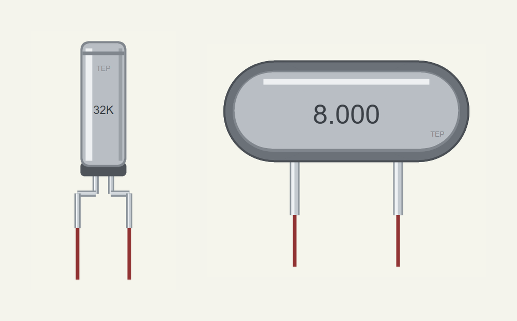
Our library has two crystals at true scale. The first is a 32.768 kHz watch crystal in the small cylinder you find next to every real-time clock chip, as the ECS-.327-12.5-13X, 2.1 x 6.2 mm. The second is an HC-49/US crystal, the low metal can used beside microcontrollers, as the ECS-80-18-4X at 8 MHz, with its frequency printed on the can. Both really oscillate: the model is the crystal's electrical twin, solved exactly at every step, so it keeps its frequency to a fraction of a ppm. The pop-up shows what an engineer measures on a real board: the frequency and its error in ppm, the load capacitance the circuit gives the crystal, the drive level, the start-up time and the start margin. The demo builds a watch-crystal oscillator from a 2N7000 and lets an Arduino time it.
NOTICE: Our team has put a lot of effort into these small parts: the bodies, the animation and the pop-ups are all our own design, and you get them free. Your feedback is the fuel that keeps us going, so please tell us what you think in the comments below or in the Crystal board of our forum. And if our free libraries help you, you can buy us a coffee. So, let's get started with the Crystal Library for Proteus:
What is a Quartz Crystal?
Quartz is piezoelectric: squeeze it and a voltage appears across it; put a voltage across it and it bends. Cut a thin slice or a tiny tuning fork from a quartz crystal, put metal electrodes on it and seal it in a can, and you have a mechanical resonator that you can drive and sense electrically. Like a bell, it rings at one frequency set by its shape and size, and it rings for a very long time: its quality factor, Q, is in the tens or hundreds of thousands. A good inductor and capacitor manage a Q of about a hundred. That sharpness is what makes a crystal so precise: a tiny change in frequency is enough to give the circuit around it any phase it needs.
| Watch crystal | HC-49/US crystal | |
|---|---|---|
| Like | ECS-.327-12.5-13X | ECS-80-18-4X |
| Size | 2.1 mm across, 6.2 mm long | 11.35 x 4.65 mm, 3.5 mm tall |
| Frequency | 32.768 kHz, tuning fork | 8 MHz, AT-cut, fundamental |
| Load capacitance (CL) | 12.5 pF | 18 pF |
| Tolerance at 25 °C | ±20 ppm | ±30 ppm |
| Motional resistance (ESR) | 35 kΩ max | 80 Ω max |
| Motional capacitance C1 | 3.0 fF | not published (the model takes 15 fF) |
| Shunt capacitance C0 | 1.35 pF | 7 pF max (the model takes 4.5 pF) |
| Drive level | 1 µW max | 500 µW max |
| Temperature | -0.034 ppm/°C² round 25 °C | a cubic curve, ±50 ppm over -10 to +70 °C |
The Electrical Twin
Electrically, a crystal near its frequency behaves exactly like a small circuit, the Butterworth-Van Dyke model. The motional arm stands for the vibrating quartz: a resistor R1 for its losses, an inductor L1 for its mass and a capacitor C1 for its stiffness, all in series. Across it sits C0, the plain capacitance of the electrodes and the leads. The values are strange for anyone used to ordinary parts: the watch crystal's L1 is about 7,870 henries and its C1 is 3 femtofarads, three thousandths of a picofarad. No coil and capacitor you could buy would come near that Q.
The arm has a series resonance, fs, where L1 and C1 cancel and the crystal looks like R1 alone. Just above it C0 resonates with the arm in a parallel resonance, fp, where its impedance shoots up. For the watch crystal the two are only about 36 Hz apart, a thousandth of its frequency. Between them the crystal is inductive, and that narrow band is where an oscillator runs it.
Load Capacitance
Exactly where a crystal runs between fs and fp depends on the capacitance the circuit puts across it, the load capacitance, CL. The crystal is cut so that it reads its marked frequency with the CL printed in its datasheet: 12.5 pF for our watch crystal. Give it less and it runs fast; give it more and it runs slow. In the usual oscillator two capacitors, one from each side of the crystal to ground, are in series: CL = C1 x C2 / (C1 + C2) plus a few picofarads of strays from the board and the amplifier. For the watch crystal each picofarad of error moves it about 8 ppm, and every ppm is 0.0864 seconds a day, so a 1 pF mistake costs more than half a second a day.
Drive Level
The current through the motional arm heats it and strains it. The power it takes, the drive level R1 x I², has a limit in the datasheet: 1 µW for a watch crystal, a few hundred µW for an HC-49 crystal. Too much and the crystal ages faster, its frequency shifts, and a tiny tuning fork can even break. Designers keep the drive down with a series resistor at the amplifier's output or with less gain.
The Pierce Oscillator
Almost every crystal oscillator, including the one inside your microcontroller, is a Pierce oscillator: an inverting amplifier with the crystal from its output back to its input and a capacitor from each end of the crystal to ground. The amplifier turns the signal upside down, 180 degrees; the two capacitors and the crystal, running in its inductive band, turn it round another 180 degrees, and the loop sustains itself. Seen from the crystal, the amplifier and its capacitors look like a negative resistance. While it is larger than R1 the oscillation grows; as it grows the amplifier runs out of gain and the amplitude settles. The ratio of that negative resistance to the crystal's worst-case ESR is the start margin, and the usual advice is five or more, so that every crystal in a batch starts at every temperature.
Why 32,768 Hz?
32,768 is 2 to the 15th power. Divide it by two fifteen times, with fifteen flip-flops, and you get exactly one pulse a second. That is why it is in every watch and every real-time clock. A tuning fork at that frequency is also small, cheap and frugal: it needs only microwatts to keep it going, so a coin cell can run a clock for years.
Temperature
A tuning-fork crystal is most accurate at its turnover temperature, about 25 °C, and runs slow on both sides along a parabola: -0.034 ppm for each degree squared. At 0 °C that is about -21 ppm, almost two seconds a day. An AT-cut crystal like the HC-49 follows a flatter cubic curve. The library has both curves: set a crystal's temperature and its frequency moves with it.
Features of the Crystal Library for Proteus
- The real look, at true scale: a nickel-silver cylinder of 2.1 x 6.2 mm and a low HC-49/US can whose printed frequency follows the value you type, each with our small TEP signature.
- It really oscillates: the Butterworth-Van Dyke circuit is solved exactly at every step, so a Q of 70,000 keeps its frequency to a small fraction of a ppm.
- The numbers a designer checks: the frequency and its error in ppm and seconds a day, the load capacitance it sees, the drive level, the start-up time and the start margin.
- Its own error and its temperature: give a part its own offset in ppm, set its temperature, and watch the frequency follow its curve.
- Any frequency: type 32.768k, 4M or 12M; AUTO takes the other values from the datasheet.
- A pop-up: the crystal and its electrical twin with their values, its reactance round resonance with where it runs, the start-up curve, eight live values, graphs, an event log and a check page.
- A complete package: about 2.3 MB with the library, our Arduino UNO V4.0, our 2N7000 MOSFETs, ceramic capacitors and resistors and the demo, without the source code of the model.
The Crystals in Proteus
The devices are CRYSTAL32KTEP and CRYSTALHC49TEP in TEPCRYSTAL.LIB, under Crystals, with the prefix X and the model TEPCRYSTAL.DLL. Search CRYSTAL in Pick Devices. Each has pins 1 and 2 and no polarity. The watch crystal stands on its seal with its two thin leads splayed to a 2.54 mm pitch; the HC-49 lies flat with its legs 4.88 mm apart.
One thing to know before you place one next to a microcontroller: Proteus's microcontroller models take their clock from a property, not from the pins, so a crystal on their oscillator pins has nothing to drive it. Our crystal sees that, says IDLE and lets the simulation run at full speed. It comes alive in a real oscillator circuit, like the one in the demo.
The Properties
| Property | What it does |
|---|---|
| Frequency (VALUE) | 32.768k, 4M, 8M, 12M (k for kHz, M for MHz) |
| Load capacitance (CL) | the CL it is cut for, in pF |
| Motional resistance (ESR) | R1 in ohms, or AUTO for the datasheet's typical value |
| Motional capacitance (CM) | C1 in fF, or AUTO |
| Shunt capacitance (C0) | in pF, or AUTO |
| This part's own error (PPM) | its offset at 25 °C in ppm; 0 is exact |
| Its temperature (TEMP) | in °C: the frequency follows the crystal's temperature curve |
| Drive level limit (DLMAX) | in µW, or AUTO |
Download Crystal Library for Proteus
Click the button below to download Crystal-Library-for-Proteus-v1.0.zip (about 2.3 MB, without the source code of the models):
Crystal Library for Proteus V1.0- README.txt: installation, the demo, the oscillator's wiring, troubleshooting and the limits.
- Proteus Library Files:
TEPCRYSTAL.LIB, our N-MOSFET, ceramic capacitor and resistor libraries, and ourArduinoV4TEP.LIB. - Proteus Model Files:
TEPCRYSTAL.DLL, the DLLs of those parts andTEPARDUINO.DLL. - Arduino Code: the demo sketch.
- Proteus Simulation: the demo project, its HEX file and copies of the DLLs.
No Proteus yet? Read How to Download and Install Proteus 7 and 8. New to libraries? Follow How to Install a New Library in Proteus.
How to Install Crystal Library for Proteus
- Close Proteus and extract the whole zip file, for example to your Desktop.
- Copy the files from Proteus Library Files into the LIBRARY folder of Proteus.
- Copy the files from Proteus Model Files into the MODELS folder.
- Delete
TEPCRYSTAL.IDXfrom the LIBRARY folder if it is there. - Start Proteus, press P and search for CRYSTAL.
Demo: A Watch-Crystal Oscillator
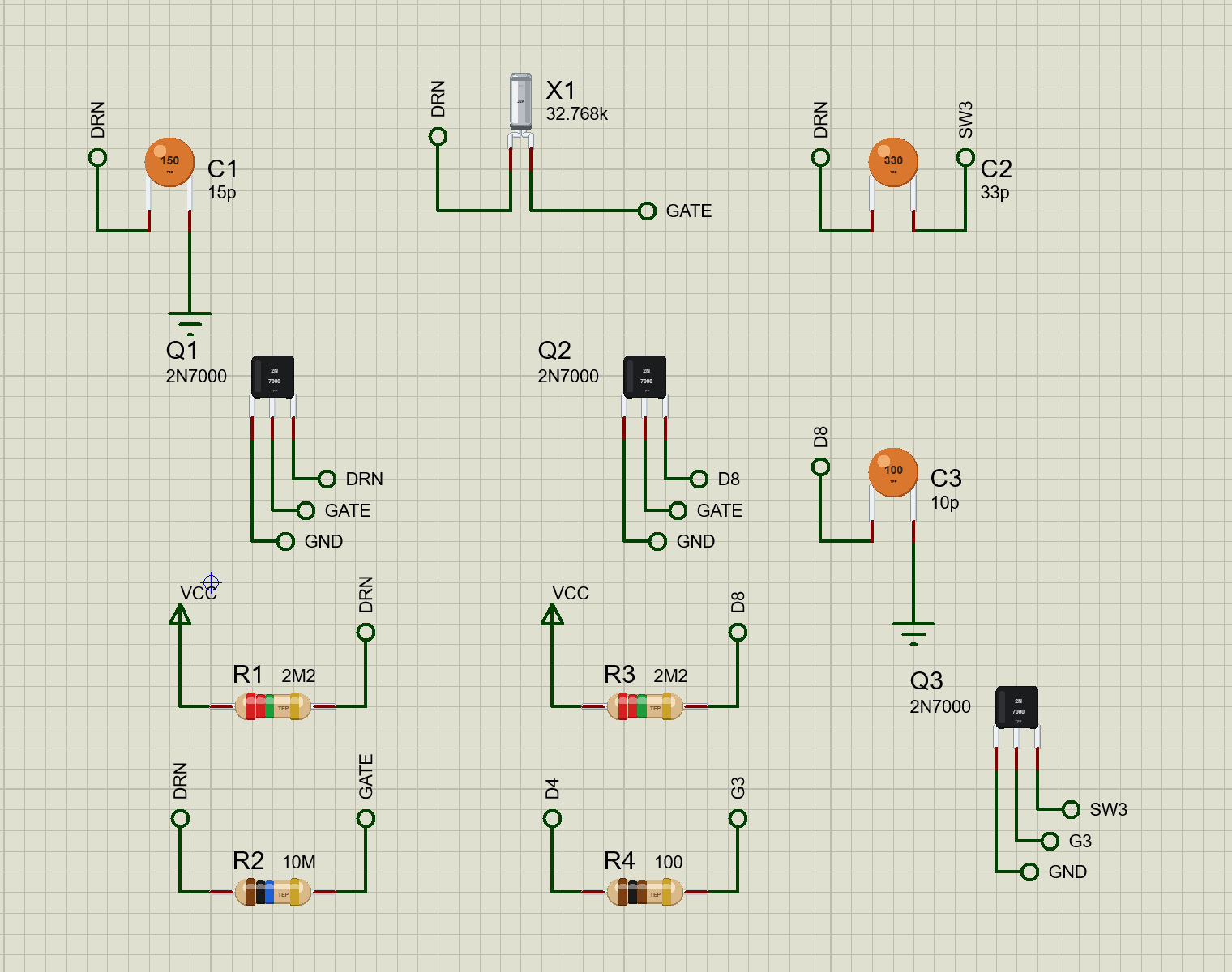
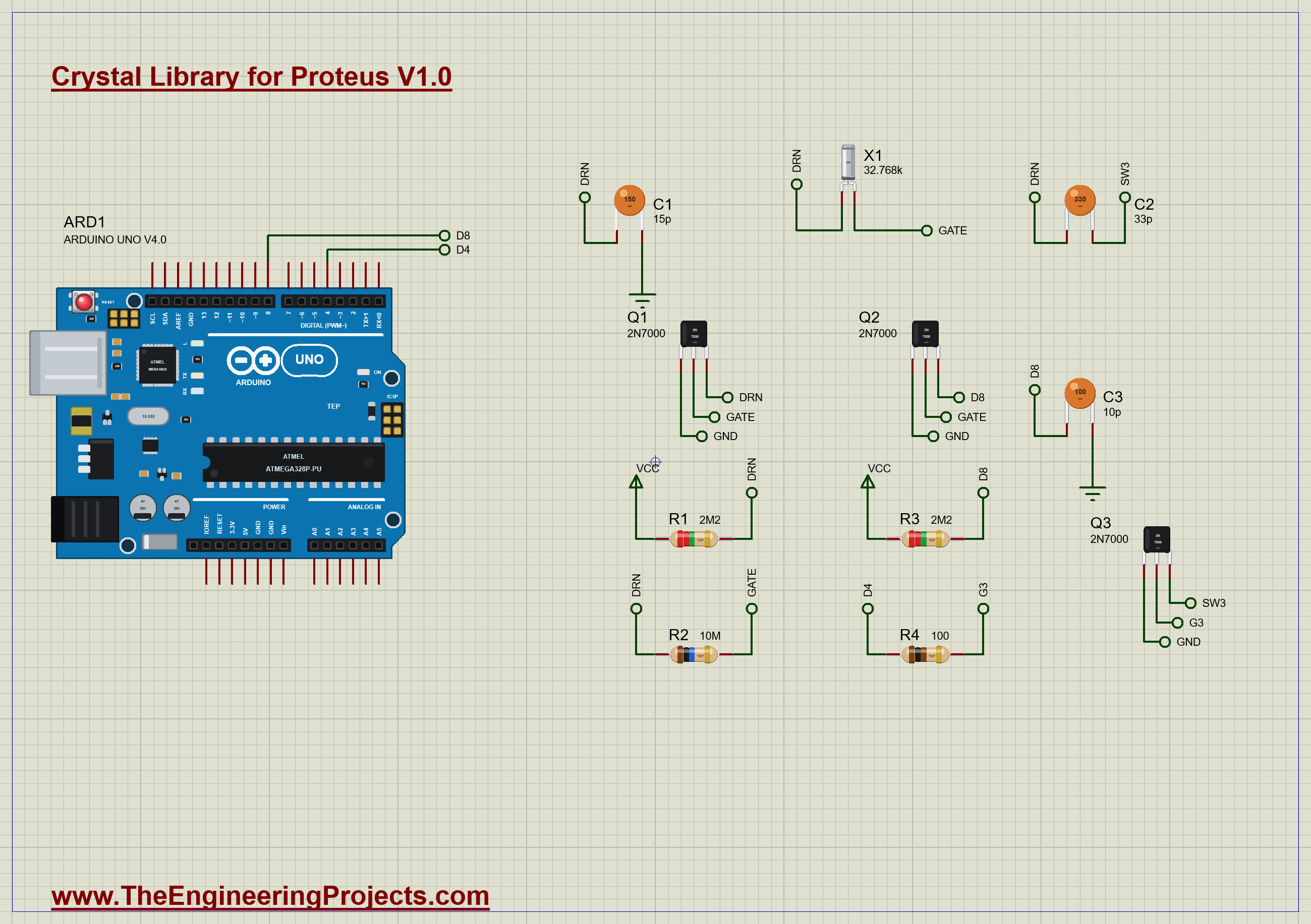
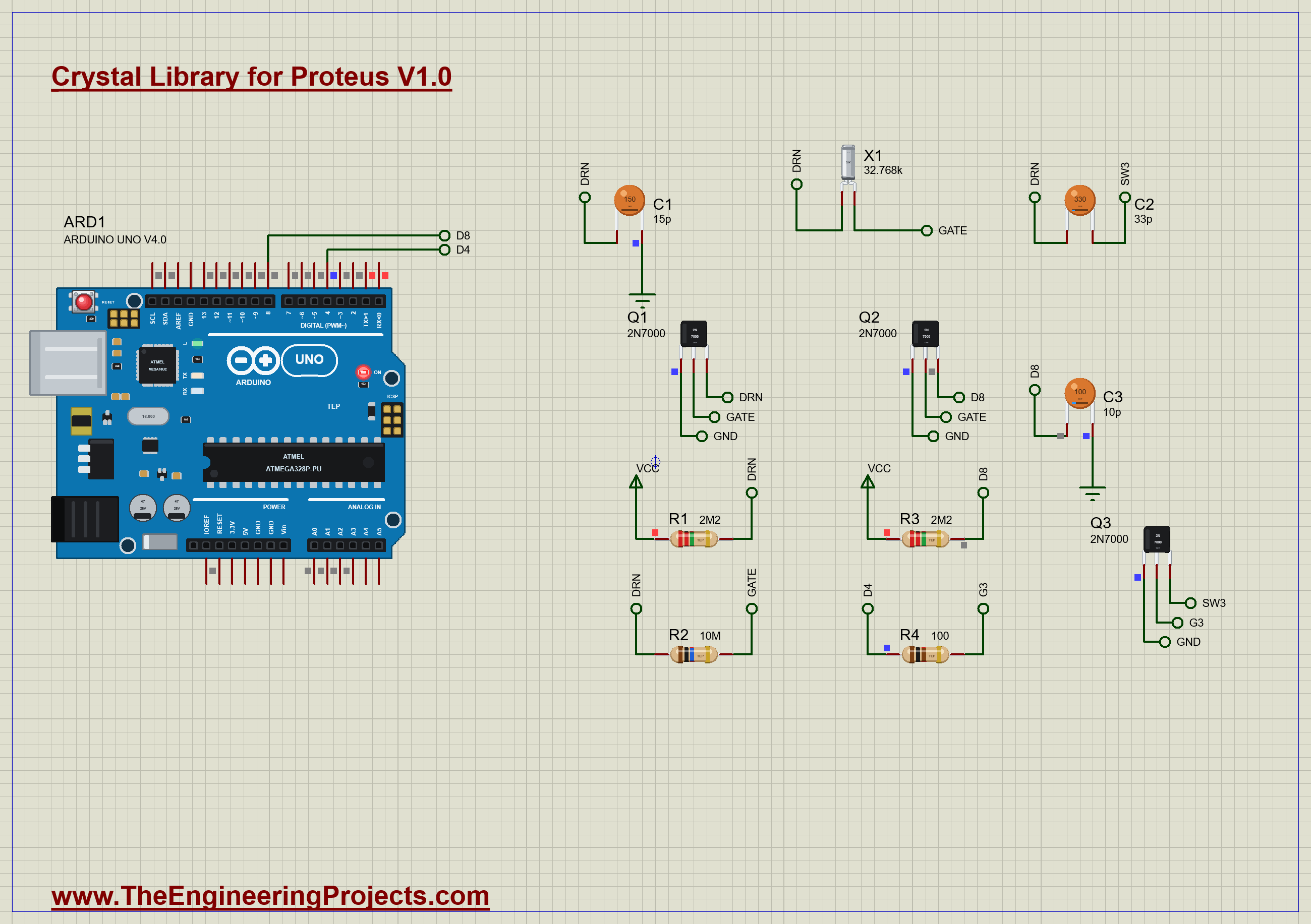
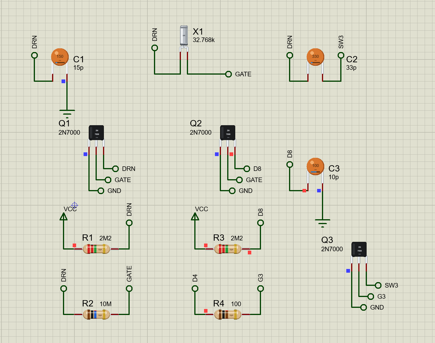
X1, the watch crystal, sits in a Pierce oscillator built on Q1, a 2N7000. R2 (10 MΩ) from the drain to the gate biases Q1 so that it amplifies, R1 (2.2 MΩ) is its load, and C1 (15 pF) loads the drain side of the crystal. On the gate side there is no capacitor to see: the gates of Q1 and Q2, about 60 pF each, are the other load capacitor. Q2, a second 2N7000 with R3 (2.2 MΩ, the same as R1, so it works at Q1's own point), copies the gate and squares the signal up for D8; C3 (10 pF) on D8 stands in for the input's own capacitance. At 2 s the sketch turns on Q3 through R4, which connects C2 (33 pF) to the drain: the crystal sees a much larger load capacitance.
Open Crystal-Pierce-ArduinoUnoV4.pdsprj. It runs on our Arduino UNO Library for Proteus V4.0, with its built-in monitor, the same window as our TEP Serial Monitor Advance for Proteus. The transistors come from our N-MOSFET Library for Proteus, the capacitors from our Ceramic Capacitor Library for Proteus and the resistors from our Resistor Library for Proteus.
| Part | Connection | Job |
|---|---|---|
| X1 watch crystal | DRN to GATE | the resonator |
| Q1 2N7000, R1 2.2M, R2 10M | G GATE, D DRN; R1 VCC - DRN; R2 DRN - GATE | the amplifier and its bias |
| C1 15 pF | DRN to GND | the drain side's load capacitor |
| Q2 2N7000, R3 2.2M, C3 10 pF | G GATE, D D8; R3 VCC - D8; C3 on D8 | the buffer |
| C2 33 pF, Q3 2N7000, R4 100 | C2 DRN - SW3; Q3 SW3 to GND; D4 - R4 - gate | the extra load, on at 2 s |
The Sketch
D8 is Timer1's input capture pin. The timer counts the UNO's own clock, and at each falling edge on D8 the hardware copies the count into ICR1, so every cycle of the crystal gets a time stamp accurate to one clock. The falling edge is the sharp one: Q2 pulls D8 down hard, while R3 pulls it up slowly, and the noise canceller ignores any glitch:
  TCCR1A = 0;
  TCCR1B = _BV(ICNC1) | _BV(CS10);               // capture falling edges (Q2 pulls D8 down sharply; it rises slowly through R3),
                                                 // with the noise canceller; the timer counts the UNO's own clock
  TIMSK1 = _BV(ICIE1) | _BV(TOIE1);
The timer is only 16 bits wide, so an overflow interrupt counts its laps and the capture interrupt joins the two into one 32-bit time stamp, taking care of an overflow that is still waiting:
ISR(TIMER1_CAPT_vect) {
  const unsigned int t = ICR1;
  unsigned int o = overflows;
  if ((TIFR1 & _BV(TOV1)) && t < 0x8000) o++;   // an overflow waiting behind this capture
  const unsigned long stamp = ((unsigned long)o << 16) | t;
The sketch times 8,192 cycles, a quarter of a second of a perfect watch crystal, and compares the count with what it should be:
const unsigned long CYCLES = 8192;               // a quarter of a second of a watch crystal
const unsigned long IDEAL = F_CPU / 4;           // the timer's count for 8,192 cycles of exactly 32,768 Hz
const float ppm = (float)((long)IDEAL - (long)ticks) / ticks * 1e6;One honest warning about this trick: in Proteus the UNO's clock is perfect, so it can measure a crystal to the ppm. A real UNO's own clock is a ceramic resonator good to about 0.5 %, five thousand ppm, so on a real bench you would measure against a frequency counter or a GPS pulse instead.
Run the Demo
Press Run. The crystal starts from a tiny disturbance, as a real one starts from the noise when the power comes on, and its oscillation grows for most of a second before the buffer gives D8 clean edges. Here is the complete circuit running:
The Start
Click X1. The banner is green: OSCILLATING at 32,768.13 Hz, +4.0 ppm, a watch that would gain 0.35 s a day, well inside the crystal's ±20 ppm. The start curve shows the oscillation creeping up from almost nothing, rising steeply and levelling off: 888 ms to 90 % of its amplitude, typical of a watch crystal. From the speed of that rise the model works out the circuit's negative resistance, 242 kΩ, 6.9 times the crystal's worst-case ESR of 35 kΩ and comfortably above the five that designers aim for. The crystal sees a load of 12.0 pF against the 12.5 pF it is cut for, so the white dot sits just above the CL line on the reactance curve and it runs a hair fast. The drive level is 383 nW, under half of its 1 µW limit, with 4.07 µA in its motional arm:
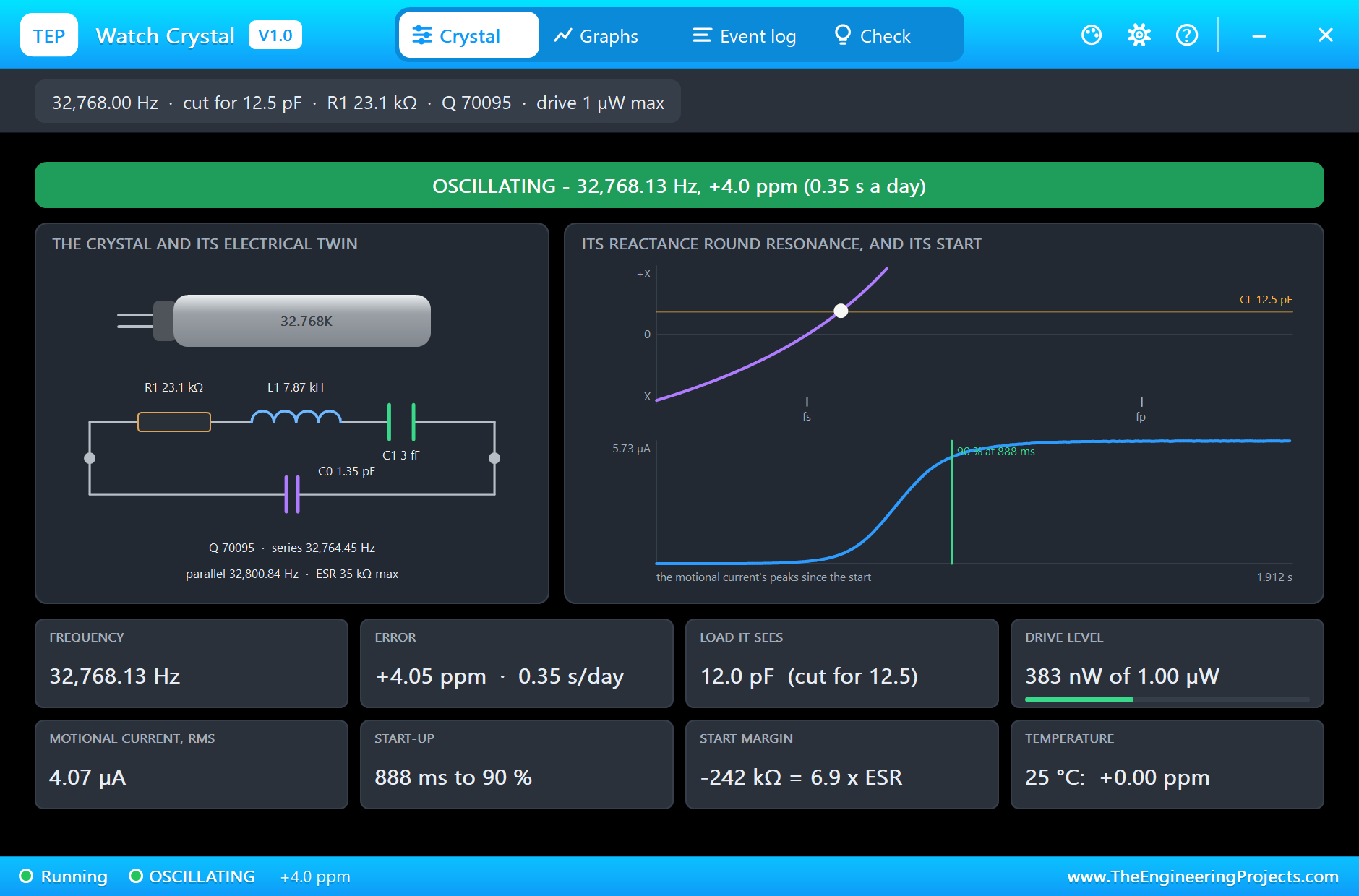
Notice the load: the schematic has no capacitor on the gate side. The gates of Q1 and Q2 are the second load capacitor, about 120 pF together; in series with C1's 15 pF that makes about 13 pF, and the amplifier's own working pulls it a little lower. Every part round a crystal belongs to its load capacitance.
The Wrong Load
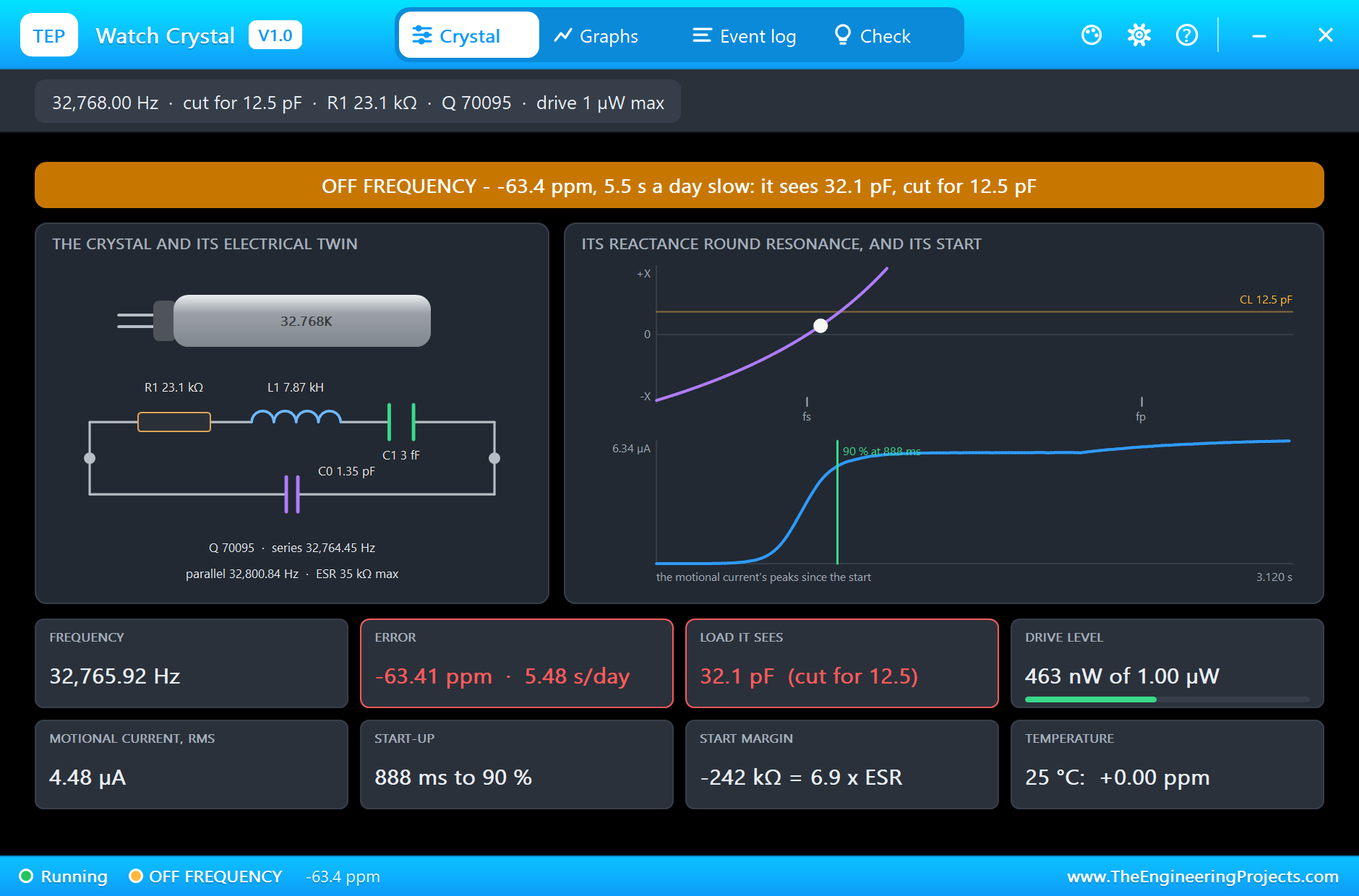
At 2 s the sketch turns on Q3, which puts C2's 33 pF on the drain beside C1. The crystal now sees 32.1 pF and is pulled down its reactance curve: the banner turns amber, OFF FREQUENCY, -63.4 ppm, 32,765.92 Hz. A clock running on it would lose 5.48 seconds a day, more than half a minute a week and three times the crystal's whole tolerance. The oscillation itself is perfectly healthy: the start margin is the same and the drive level is 463 nW. Only the capacitors are wrong, and that is exactly how this mistake hides on a real board: the clock works, it is just wrong.
The Monitor
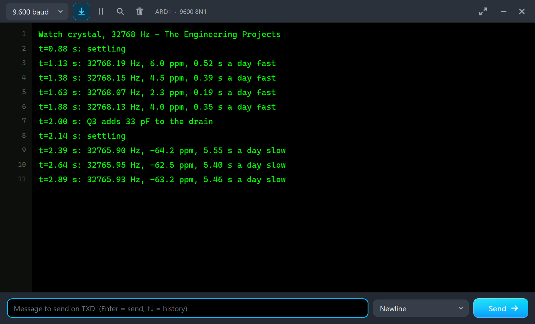
The monitor tells the same story from the Arduino's side. Before the change it reads +6.0, +4.5, +2.3 and +4.0 ppm; after it, -64.2, -62.5 and -63.2 ppm. A reading that falls while the oscillation grows, or holds both loads, says settling, because it is not a frequency. The small scatter comes from the simulator, not the crystal: an edge reaches the UNO on a simulation step, about a microsecond apart, and a microsecond in a quarter of a second is 4 ppm. The first four readings average +4.2 ppm and the last three -63.3 ppm, in step with the crystal's own +4.05 and -63.41 ppm:
The Graphs, the Log and the Check Page
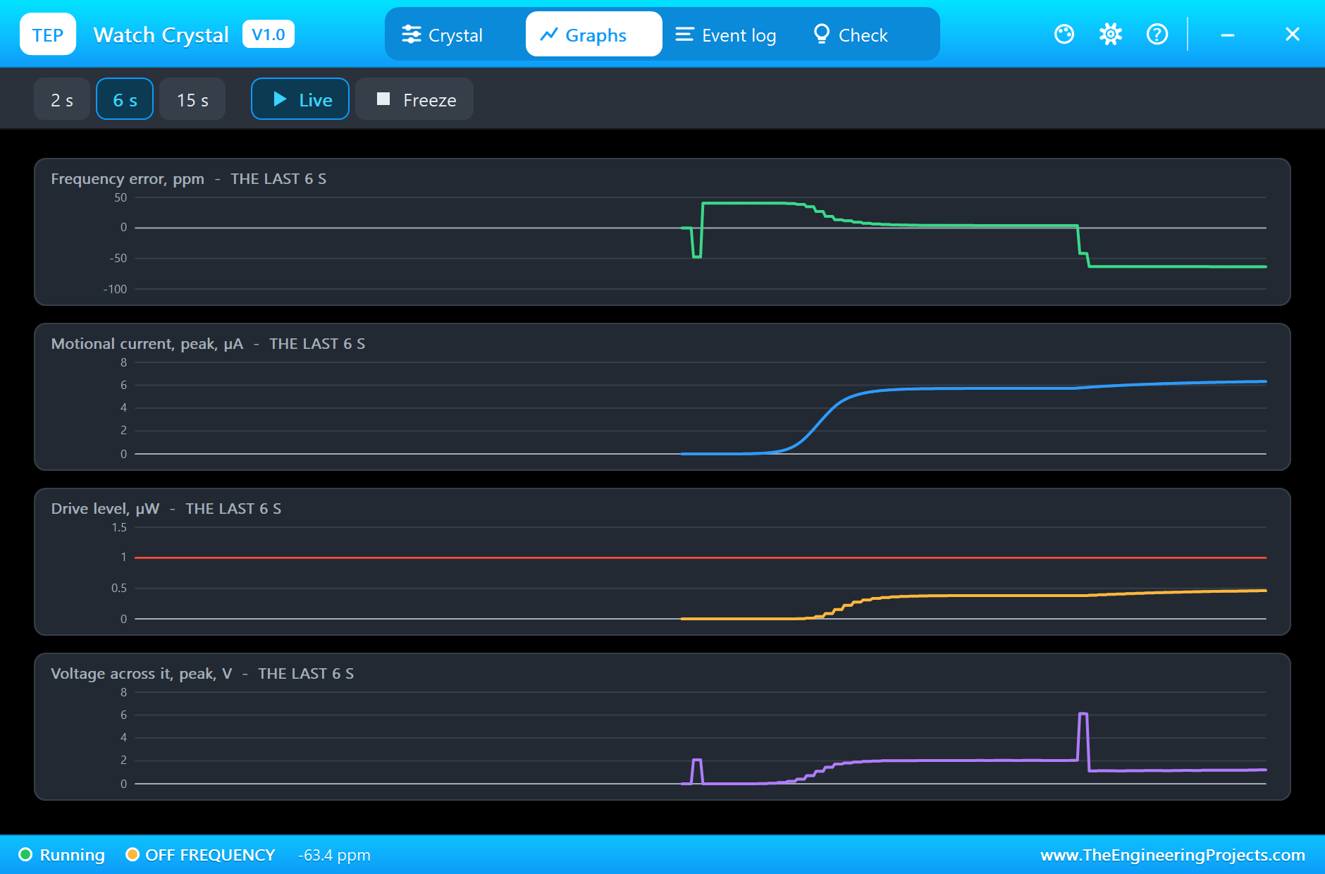
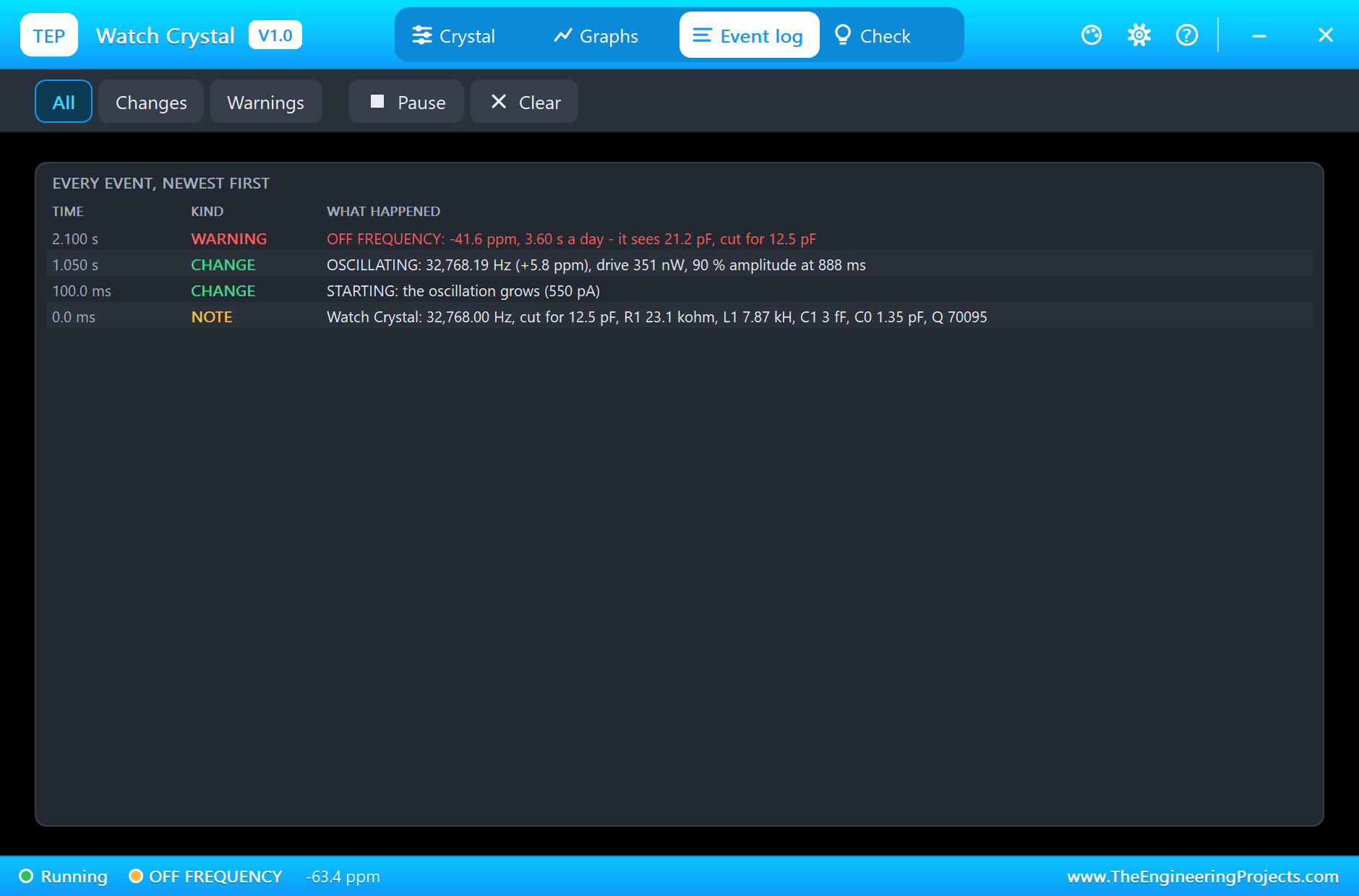
The Graphs page shows the run: the frequency error settling to about +4 ppm as the oscillation grows and stepping to -63 ppm at 2 s; the motional current rising in an S-curve to about 6 µA; the drive level well under its red 1 µW line; and the voltage across the crystal, which halves when C2 joins the drain. The Event log lists the start at 100 ms, OSCILLATING at 1.05 s with 90 % of the amplitude at 888 ms, and the OFF FREQUENCY warning at 2.1 s, caught while the oscillator was still moving to its new frequency:
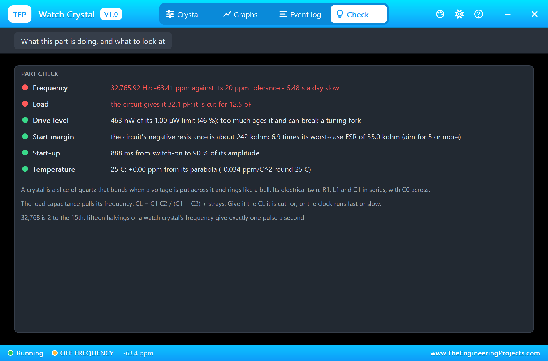
The Check page grades the circuit as it stands at the end. Frequency and load are red: -63.41 ppm against a 20 ppm tolerance, and 32.1 pF against the 12.5 pF it is cut for. Drive level, start margin, start-up and temperature are green: 463 nW is 46 % of the limit, the margin is 6.9 times the worst-case ESR, and at 25 °C the parabola adds nothing:
Try It Yourself
- Change C1 to 22 pF: the load grows and the crystal runs about 25 ppm slower.
- Set X1's temperature to 0 °C: the parabola takes about 21 ppm off.
- Give X1 an error of its own with the PPM property and see the measurement follow it.
- Change R1 to 4.7 MΩ: the start margin falls and the start takes much longer.
- Put an HC-49 crystal at 4M in its own oscillator with 22 pF capacitors; it needs more gain, and much smaller steps, so it simulates slowly.
Ideas to Extend the Demo
- Count 32,768 edges for a crystal-timed seconds clock on an LCD.
- Divide the oscillator by 2 fifteen times with a ripple counter and blink an LED once a second.
- Add a trimmer capacitor and trim the oscillator to within 1 ppm.
- Log the error against temperature and draw the crystal's parabola.
Your Own Sketches
The demo sketch is in the zip file, and you can change it in the Arduino IDE. New to Arduino? Start with our Arduino Tutorial for Beginners. Export the compiled binary, and set the UNO's PROGRAM property to the new file. Our guide on How to get the HEX file from Arduino shows you where the file ends up.
Things to Know Before Using a Real Crystal
- Count every picofarad: the two load capacitors in series, plus the board's strays and the amplifier's own capacitance, should equal the crystal's CL.
- Mind the drive level: a watch crystal takes 1 µW at most; add a series resistor if the amplifier is strong.
- Check the start margin: five times the worst-case ESR, so every part starts at every temperature.
- Keep it close: short tracks to the oscillator pins, a ground under the crystal and no noisy lines nearby.
- Do not overheat it when soldering: a tuning fork in a cylinder is delicate; solder its leads quickly and away from the can.
Troubleshooting
- IDLE: no oscillation; the crystal needs an amplifier and its load capacitors round it.
- It never starts: too little gain (a small start margin) or too much load capacitance.
- OFF FREQUENCY: the circuit's load capacitance differs from the CL it is cut for; change the capacitors.
- OVERDRIVEN: past its drive limit; add a series resistor or lower the gain.
- Timestep too small on a buffer's output: give that node a little capacitance, like C3 here.
- The part is not simulated:
TEPCRYSTAL.DLLis missing from MODELS and from the project folder.
Limitations of the Simulation
- Overtones, spurious modes, aging, and the frequency's small shift with the drive level are not modelled; an overdriven crystal is reported but not damaged.
- No HC-49 datasheet publishes C1; the model's 15 fF, 40 Ω and 4.5 pF are typical values for such a crystal.
- The start begins from a small current, as switching on gives a real crystal; a real start also depends on noise and the supply's rise.
- A crystal oscillator is slow to simulate: each cycle needs about thirty steps, so each second of the demo takes several minutes, and an 8 MHz oscillator far longer.
- Arduino is a name of Arduino; this library is not made or endorsed by Arduino or Labcenter.
- Tested in Proteus 8.5 in November 2026 (the demo as shipped). Proteus 7 is not supported.
So, that was all about the Crystal Library for Proteus. I hope it helps you see what really happens inside the little can that keeps your projects on time, and why the capacitors next to it matter so much. If you have any questions, ask in the comments and I will help you out. Till the next tutorial, take care and have fun!

Comments
0