


SMD Resistor Library for Proteus: Real 1206 and 2512 Chip Codes


Hello friends, I hope you all are doing great. Today, I am going to share the new SMD Resistor Library for Proteus. Open almost any modern circuit board, an Arduino, a phone charger or a Wi-Fi module, and you will hardly find a resistor with legs and colour bands. Instead you will see dozens of tiny black rectangles sitting flat on the board, each with a short number printed on top. Those are SMD resistors, and they are by far the most common electronic part in the world.
SMD Resistor Library for Proteus
Latest version: V1.0 (November 2026, this tutorial)
Helping Tools
- Serial Monitor Advance: a serial terminal window for the UART of your board
- Serial Monitor Expert: the serial monitor with extra debugging tools
- LCD Library for Proteus V3.0: 16x2, 20x4 and I2C LCDs to show your readings
Our library has two of them, at true scale: the 1206, 3.2 by 1.6 mm, rated 0.25 W, and the bigger 2512, 6.4 by 3.2 mm, rated 1 W. Each has a black coat over a white ceramic body and tinned ends. Type a value and the printed code follows: 220 becomes 221, 4.7k becomes 472, and 4.7 ohm becomes 4R7. The chip also warms up with the power it burns, glows when it is overloaded, and can even burn out, just like the real thing. The demo shows the codes at work, and the same resistor value in both sizes, so you can see for yourself why size matters.
NOTICE: Our team has put a lot of effort into these small parts: the bodies, the animation and the pop-ups are all our own design, and you get them free. Your feedback is the fuel that keeps us going, so please tell us what you think in the comments below or in the SMD Resistor board of our forum. And if our free libraries help you, you can buy us a coffee. So, let's get started with the SMD Resistor Library for Proteus:
What is an SMD Resistor?
SMD stands for surface mount device. Instead of pushing wire legs through holes in the board, the part sits on flat copper pads on the surface, and it is soldered there at both ends. With no legs to bend and no holes to drill, a machine can place thousands of them an hour, and both sides of the board can be used. That is why an SMD resistor costs a fraction of a cent, and why a phone can hold hundreds of them.
Our parts are thick film chip resistors, the everyday kind. A small block of white ceramic carries a layer of resistive paste, printed on and baked hard. A laser then cuts a groove into that layer to trim it to the exact value. A protective coat goes over the top, usually black, and the ends are plated with nickel and tin so that they solder well. It is a remarkably simple part, made in astonishing numbers.
| Feature | The real part | In the library |
|---|---|---|
| 1206 size | 3.2 x 1.6 mm, 0.25 W | 134 x 67 thou, true scale |
| 2512 size | 6.4 x 3.2 mm, 1 W | 269 x 134 thou, true scale |
| Marking | a printed code on top | the code follows the value |
| Heat | into the board through its ends | warms, glows, chars past 350 C |
| Pins | two soldered ends | 1 and 2 |
The Size Codes
An SMD size is named by a four-digit code made from its length and width. The common codes are in inches: 1206 means 0.12 by 0.06 inch, which is 3.2 by 1.6 mm. Be careful, because there is a metric naming too, in millimetres, and the two can clash. The tiny imperial 0201 is called 0603 in metric, while an imperial 0603 is a different, much bigger part. Shops almost always use the inch codes, but it is worth checking which system a drawing uses.
| Imperial code | Size, mm | Typical power | Printed code |
|---|---|---|---|
| 0402 | 1.0 x 0.5 | 1/16 W | usually none |
| 0603 | 1.6 x 0.8 | 1/10 W | three digits, or EIA-96 |
| 0805 | 2.0 x 1.25 | 1/8 W | three or four digits |
| 1206 | 3.2 x 1.6 | 1/4 W | three or four digits |
| 2512 | 6.4 x 3.2 | 1 W | three or four digits |
Reading the Code
The printed code is the SMD version of the colour bands we met in our Resistor Library for Proteus, and it is easier to read. A 5 % part uses three digits. The first two are the value, and the last one says how many zeros follow. So 472 is 47 followed by two zeros, which is 4700 ohm, or 4.7k. 103 is 10 and three zeros, 10k. And 470 is 47 with no zeros at all, just 47 ohm, which catches many beginners out.
Below 10 ohm there is no room for a power of ten, so the letter R marks the decimal point. 4R7 is 4.7 ohm, 1R0 is 1 ohm and R47 is 0.47 ohm. A 1 % part prints four digits, three for the value and one for the zeros, so 4701 is 470 and one zero, again 4.7k. And a chip printed 000 is a zero-ohm link, a plain jumper in a resistor's body, used so that a machine can place a wire.
| Code | Reads as | Value |
|---|---|---|
| 221 | 22 and one zero | 220 ohm |
| 472 | 47 and two zeros | 4.7k |
| 103 | 10 and three zeros | 10k |
| 470 | 47 and no zeros | 47 ohm |
| 4R7 | R is the point | 4.7 ohm |
| 4701 | 470 and one zero (1 %) | 4.7k |
| 000 | a link | 0 ohm |
The smallest 1 % chips use a third system, called EIA-96: two digits that point into a table of 96 values, and a letter for the multiplier, so 01C means 10k. It is clever but impossible to read without the table. And the tiniest chips, 0402 and below, carry no marking at all. Our parts print the three-digit and four-digit codes.
Where Does the Heat Go?
A resistor with legs gets rid of its heat into the air around it. A chip resistor is so small that it cannot. Almost all its heat flows out through its two ends, into the solder and the copper pads of the board. That is why a chip's power rating depends on the board: a 1206 on a tiny pad may struggle with its full 0.25 W, while the same chip on a wide copper area runs cooler. Designers keep a chip well under its rating, often under half, and they use a bigger size where the power is high.
A bigger chip has more ceramic to spread the heat and bigger ends to pass it into the board. The 2512 is the usual choice for a power resistor on a board, and for current sense resistors, the very low value parts, such as R010 for 0.01 ohm, that let a circuit measure a large current by the tiny voltage across them.
Soldering Them by Hand
Sizes 1206 and 0805 are friendly to a soldering iron. Put a little solder on one pad, hold the chip with tweezers, melt the solder to fix one end, then solder the other end. The 0603 needs a steady hand, and 0402 and smaller really want a hot air station. Watch out for tombstoning, when one end melts first and surface tension stands the chip up on its end, like a little gravestone. Even heat on both pads prevents it.
Features of the SMD Resistor Library for Proteus
- The real look, at true scale: a black coat over white ceramic, tinned ends, and our small TEP signature in the corner.
- Two sizes: the 1206 at 0.25 W and the 2512 at 1 W.
- The code follows the value: three digits for 5 %, four for 1 %, R for the decimal point and 000 for a link.
- Live value changes: the E24 chips in the pop-up step the value at Run, and the code repaints at once.
- It heats, glows and burns: the chip warms with its power, glows when overloaded, and chars and opens past 350 C.
- The code read out: the pop-up explains every digit of the code.
- A pop-up for every part: click the chip at Run for the code, eight live values, graphs, an event log and a check page.
- A complete package: about 1.5 MB with the library, our Arduino UNO V4.0, the demo's LEDs and the demo, without the source code of the models.
The SMD Resistors in Proteus
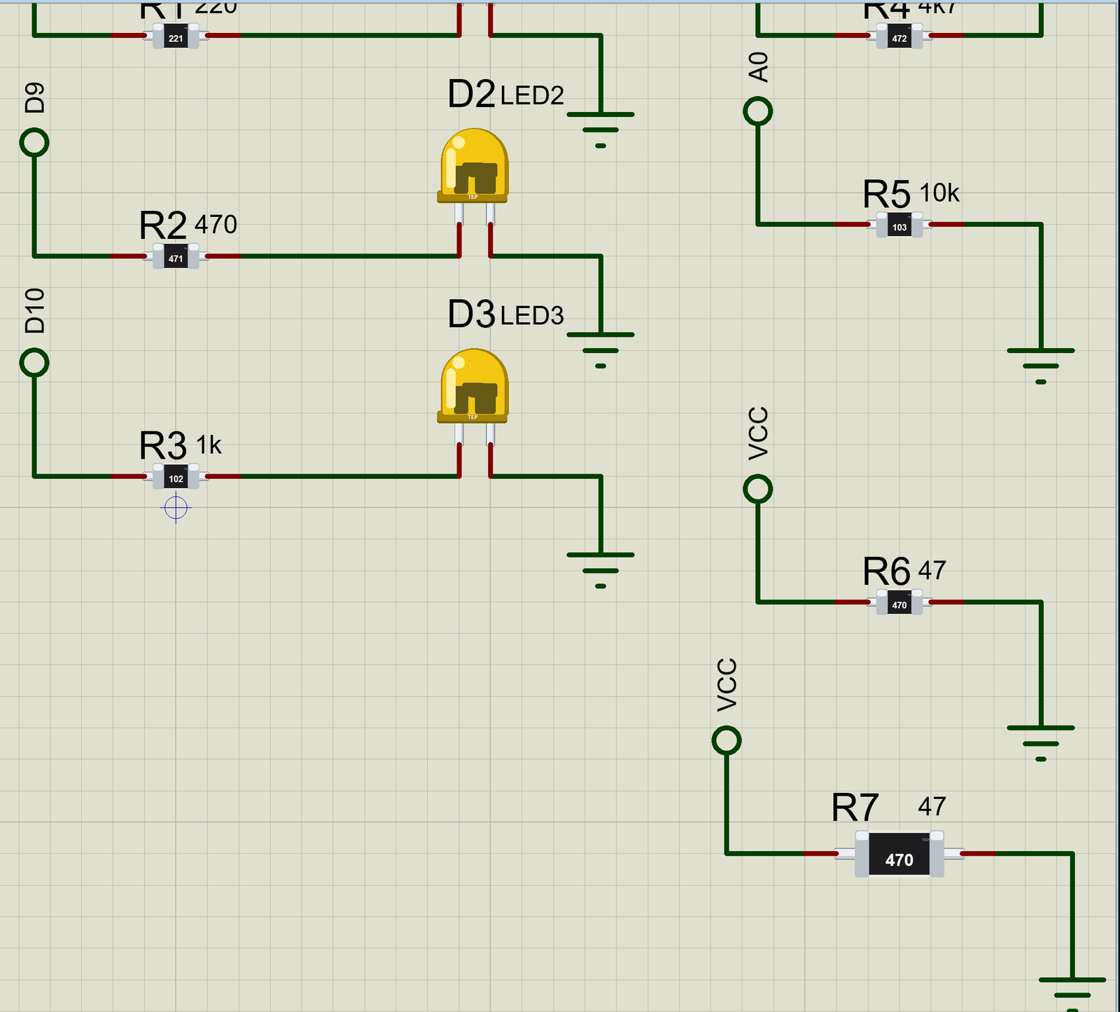
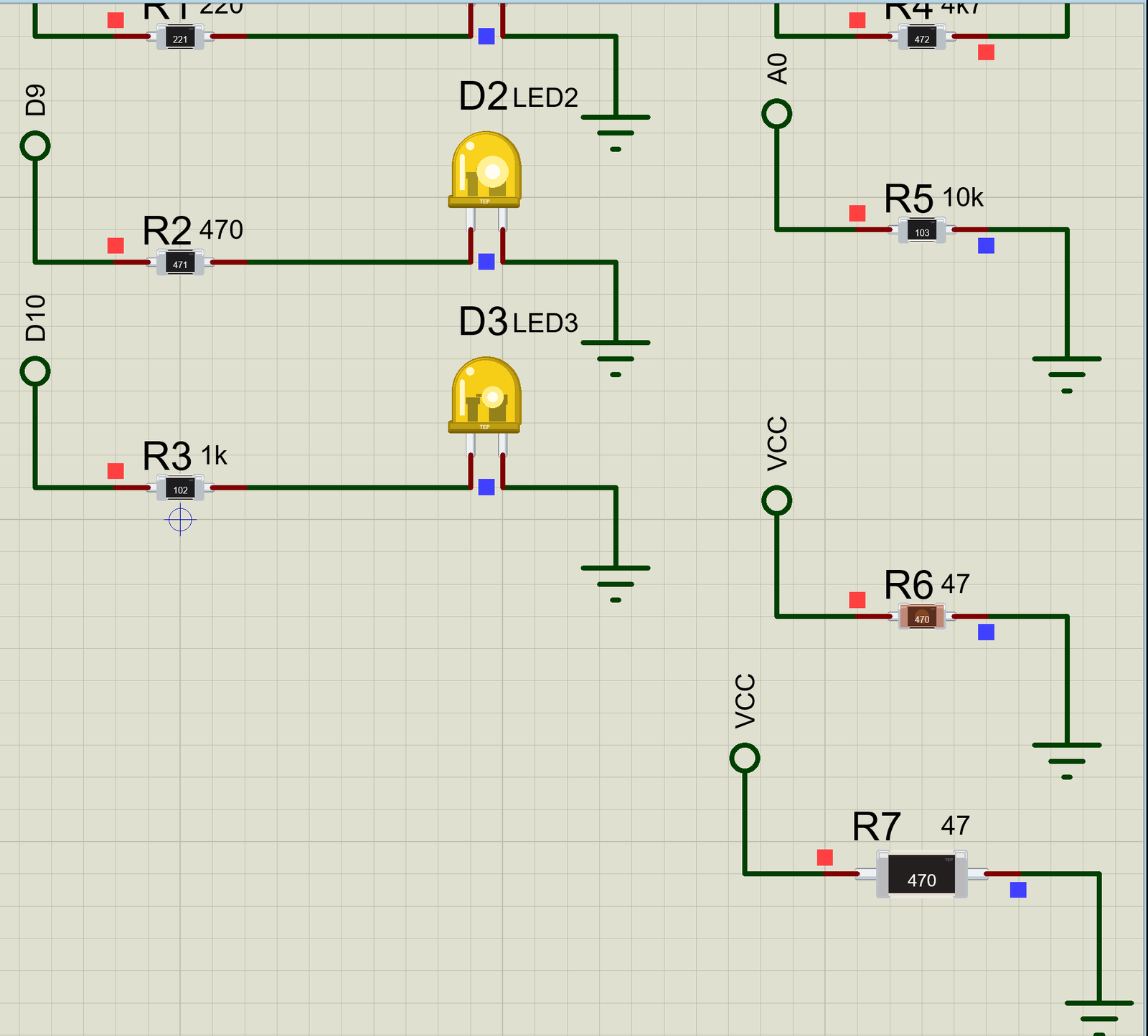
The devices are RESISTORSMD1206TEP and RESISTORSMD2512TEP in TEPSMDRES.LIB, under Resistors, Chip Resistors, with the prefix R and the model TEPSMDRES.DLL. Search RESISTORSMD in Pick Devices. Both have two pins, 1 and 2. At true scale they are small, so zoom in to read the codes, as in this view of the demo:
The Properties
| Property | What it does |
|---|---|
| Resistance (VALUE) | type 220, 4k7, 2.2M or 4R7; the code follows |
| Tolerance, % | 5 prints three digits, 1 prints four |
| Power rating, W | 0.25 for the 1206, 1 for the 2512 |
| Code while stopped | the code the sheet shows while stopped; the run sets it to match the value |
Download SMD Resistor Library for Proteus
Click the button below to download SMD-Resistor-Library-for-Proteus-v1.0.zip (about 1.5 MB, without the source code of the models):
SMD Resistor Library for Proteus V1.0- README.txt: installation, the demo, the properties, troubleshooting and the limits.
- Proteus Library Files:
TEPSMDRES.LIB,TEPLED5MM.LIBand ourArduinoV4TEP.LIB. - Proteus Model Files:
TEPSMDRES.DLL,TEPLED5MM.DLLandTEPARDUINO.DLL. - Arduino Code: the demo sketch.
- Proteus Simulation: the demo project, its HEX file and copies of the DLLs.
No Proteus yet? Read How to Download and Install Proteus 7 and 8. New to libraries? Follow How to Install a New Library in Proteus.
How to Install SMD Resistor Library for Proteus
- Close Proteus and extract the whole zip file, for example to your Desktop.
- Copy the files from Proteus Library Files into the LIBRARY folder of Proteus.
- Copy the files from Proteus Model Files into the MODELS folder.
- Delete
TEPSMDRES.IDXfrom the LIBRARY folder if it is there. - Start Proteus, press P and search for RESISTORSMD.
Demo: Codes at Work
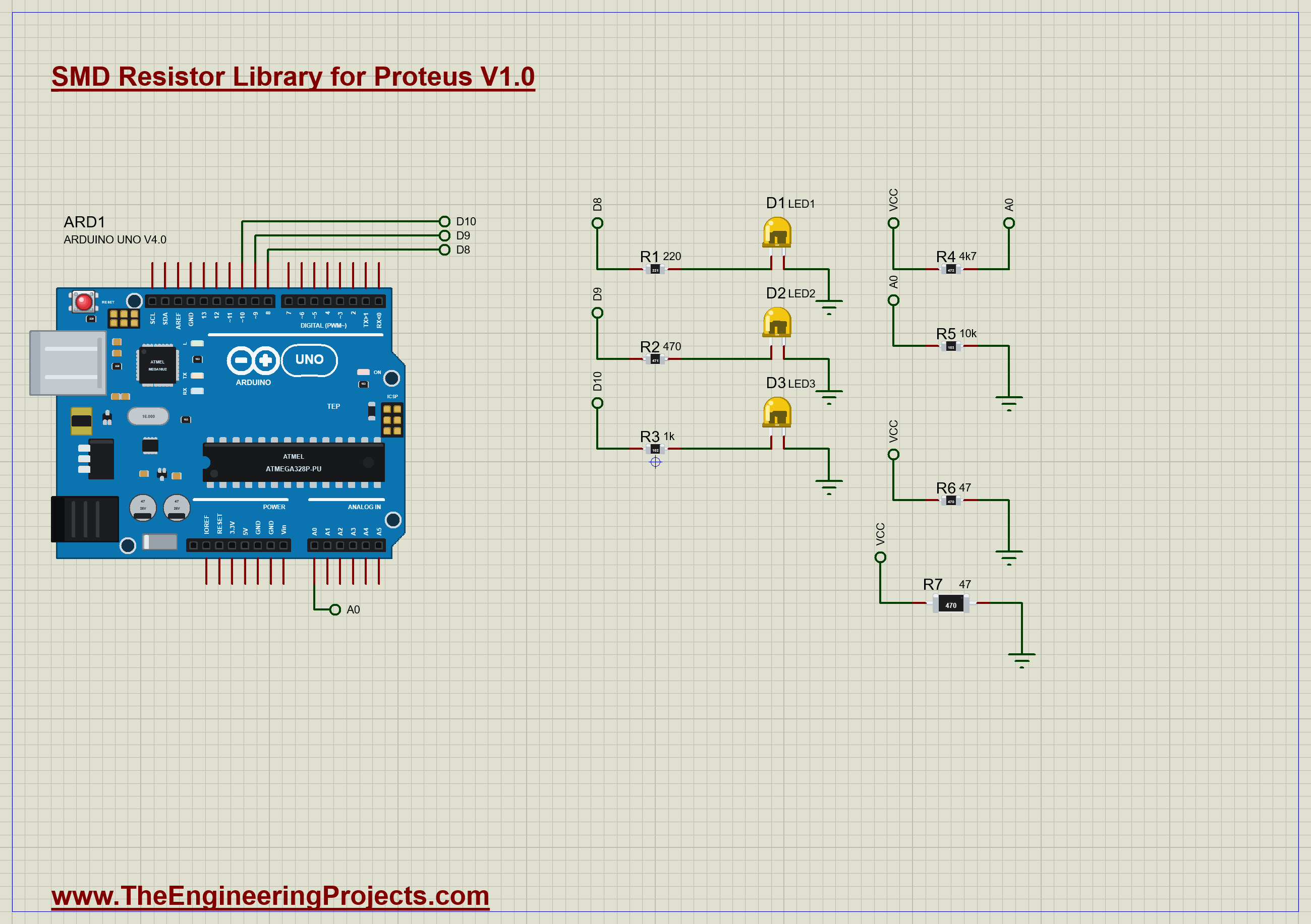
The demo has three small jobs on one sheet. Three yellow LEDs, D1 to D3, run from D8, D9 and D10 through chips printed 221, 471 and 102. A divider of 472 over 103 feeds A0. And the same 47 ohm value sits across 5 V twice, once as a 1206 (R6) and once as a 2512 (R7). Open SMD-Resistor-Codes-ArduinoUnoV4.pdsprj. It runs on our Arduino UNO Library for Proteus V4.0, with its built-in monitor, the same window as our TEP Serial Monitor Advance for Proteus. The LEDs are from our 5 mm LED Library for Proteus, and if you like tiny parts, our SMD LED Library for Proteus pairs well with these chips.
| Part | Code | Job |
|---|---|---|
| R1, R2, R3 | 221, 471, 102 | set three LED currents |
| R4, R5 | 472 over 103 | a divider on A0 |
| R6 (1206) | 470 | 47 ohm across 5 V, too much for its size |
| R7 (2512) | 470 | the same 47 ohm, in a bigger chip |
The Sketch
The sketch lights the three LEDs, and then it checks the divider. It uses the two values from the codes to predict the voltage on A0:
float predicted = 5.0 * BOTTOM_OHMS / (TOP_OHMS + BOTTOM_OHMS);Then, in the loop, it reads A0 sixteen times and averages them, which smooths out the noise of a single reading:
  for (byte k = 0; k < 16; k++) sum += analogRead(DIVIDER_PIN);
  return sum / 16.0 * 5.0 / 1023.0;
Run the Demo
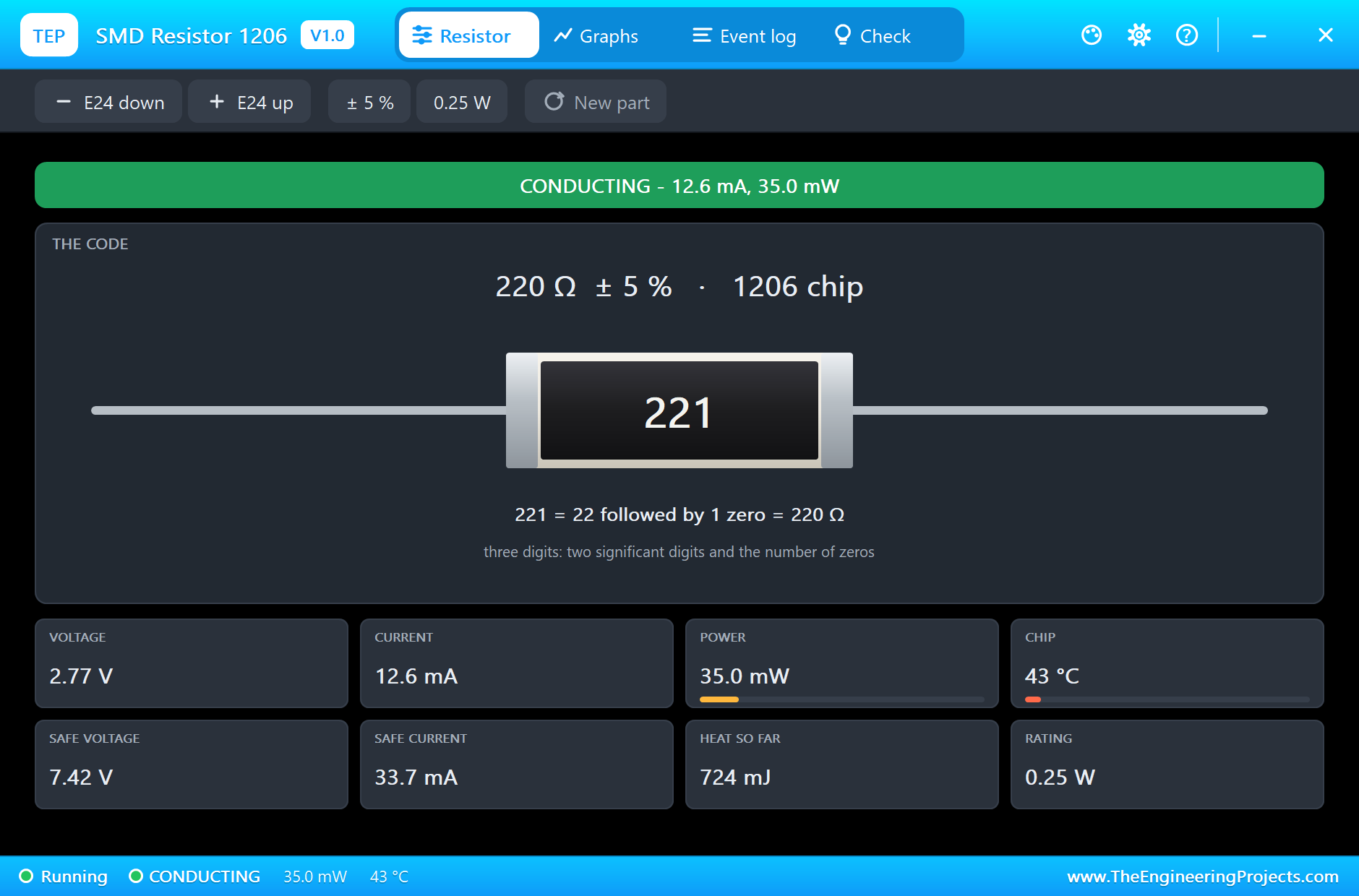
Press Run. The three LEDs light at different brightnesses. Click R1 to open its pop-up. The top card reads out its code: 221 is 22 followed by one zero, which is 220 ohm. It carries 12.6 mA to its LED:
Here is the complete circuit, truly running:
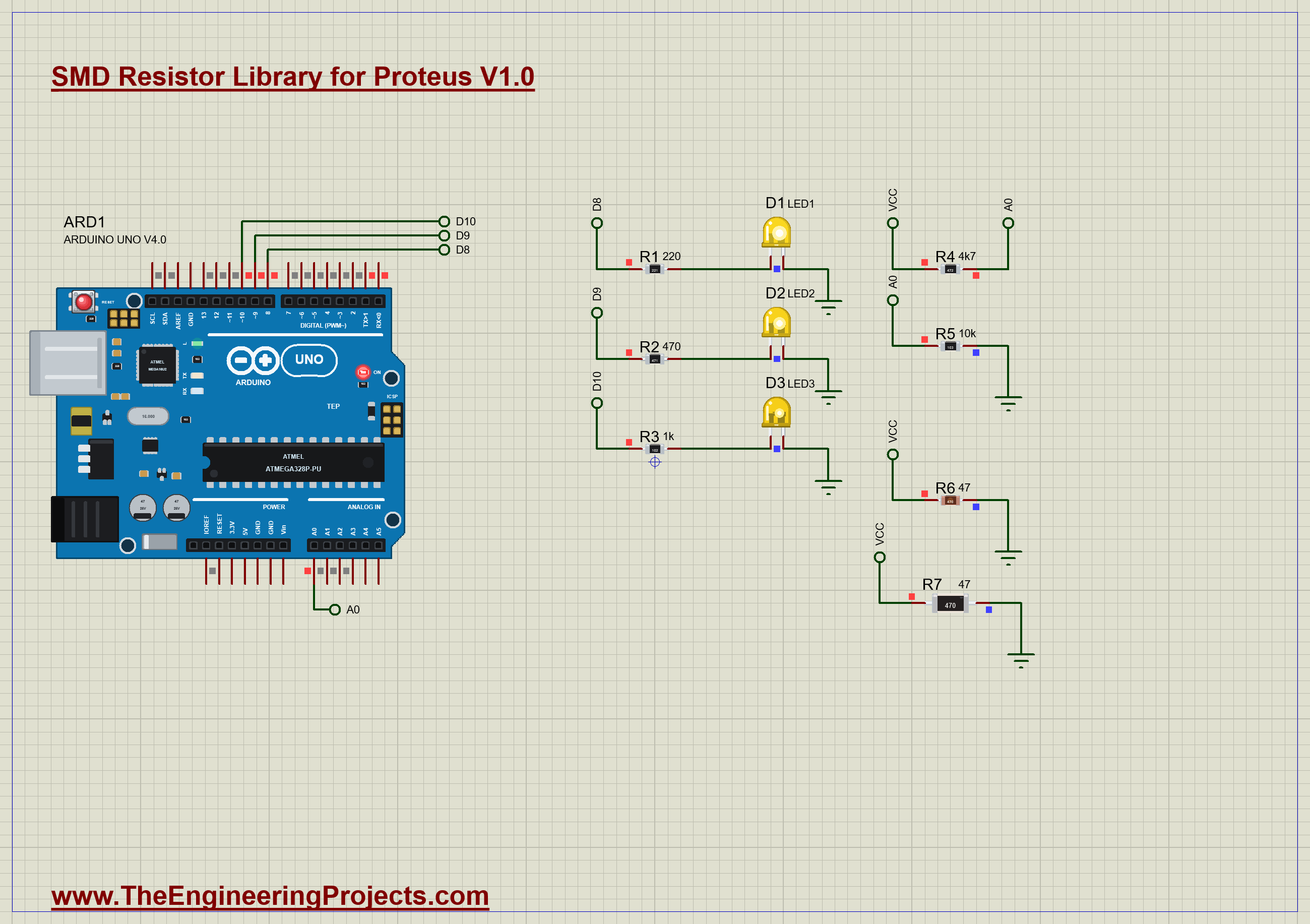
Zoom in, and you can read every code on the running sheet. The three LEDs run at 12.6, 6.4 and 3.2 mA through 221, 471 and 102, so each step up in the code makes its LED dimmer. And look at R6: the little 1206 has turned a hot brown:
The Divider
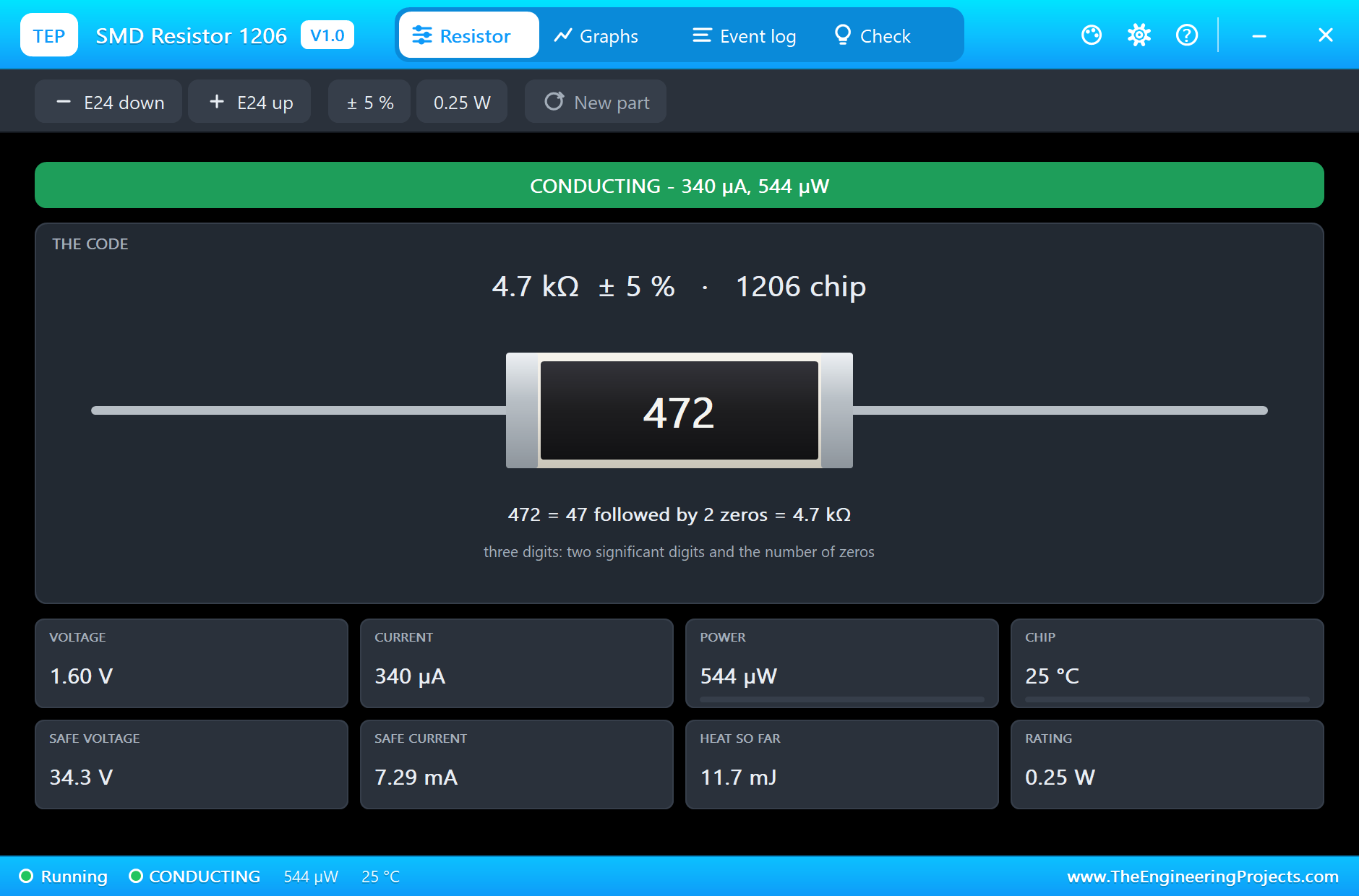
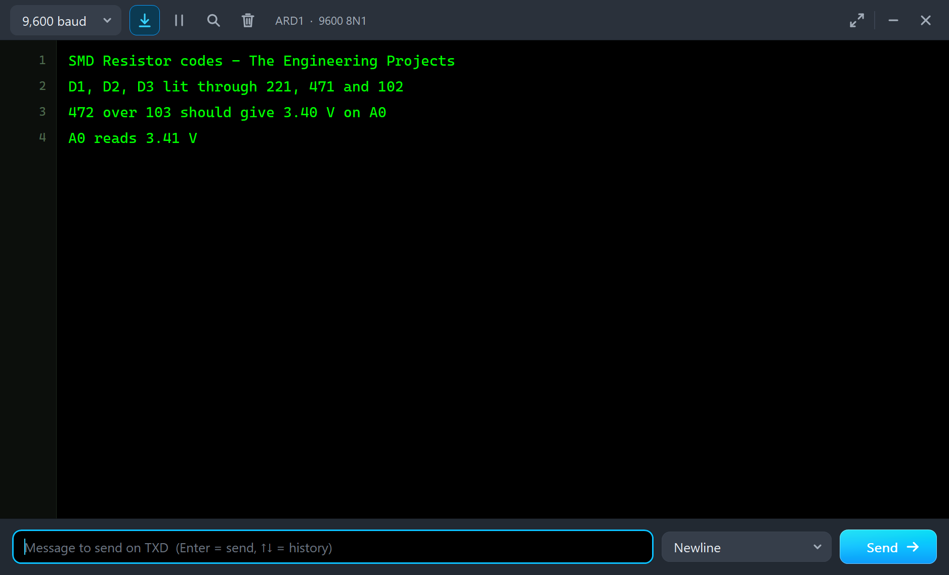
R4 is printed 472, and R5 is printed 103. By the codes, the divider should put 3.40 V on A0. The pop-up of R4 shows the code and its share of the current:
One Value, Two Sizes
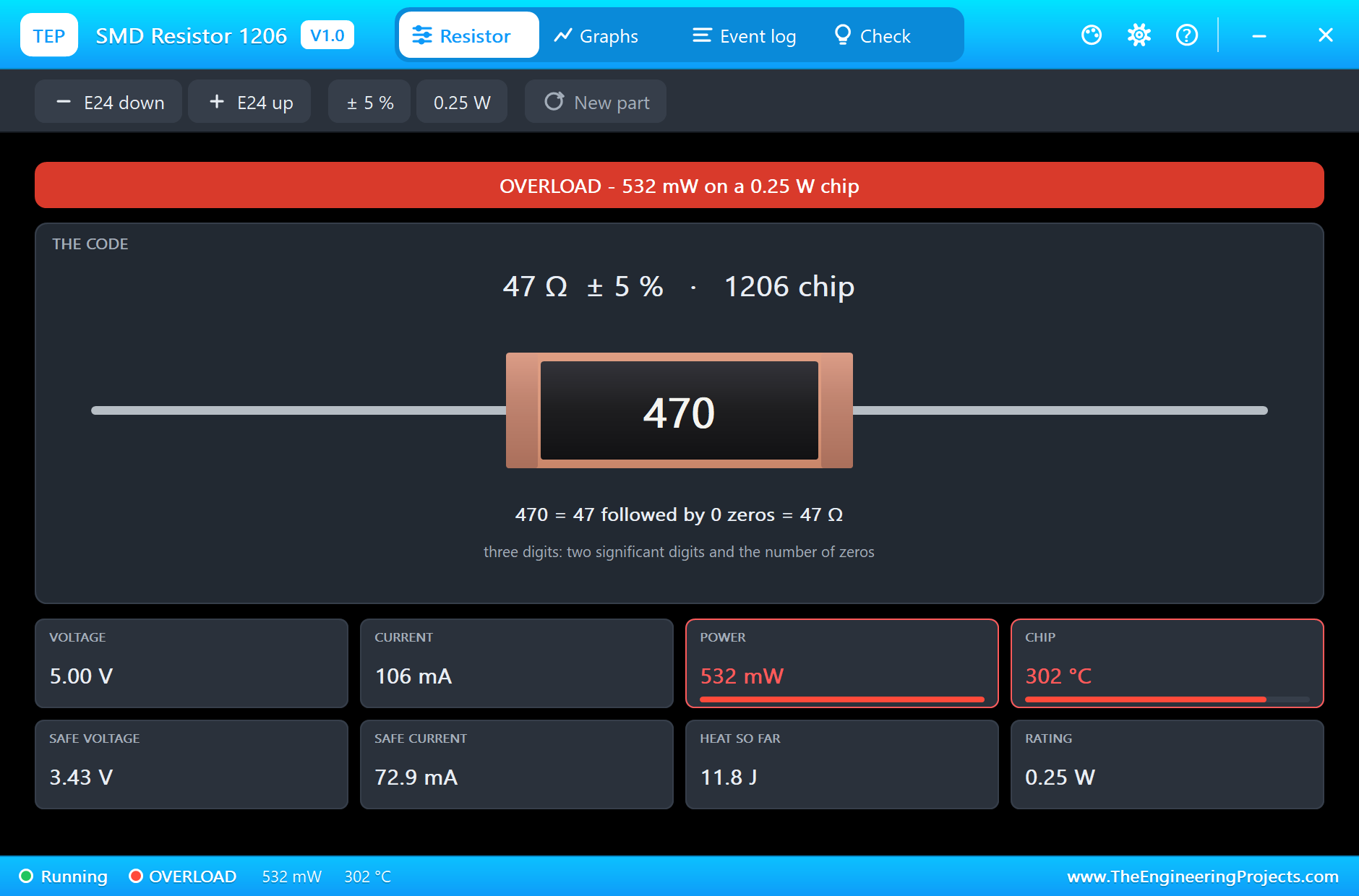
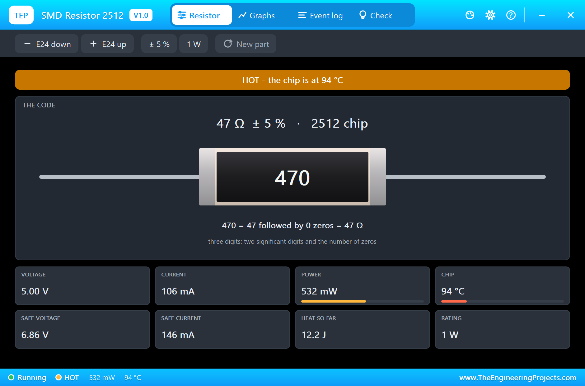
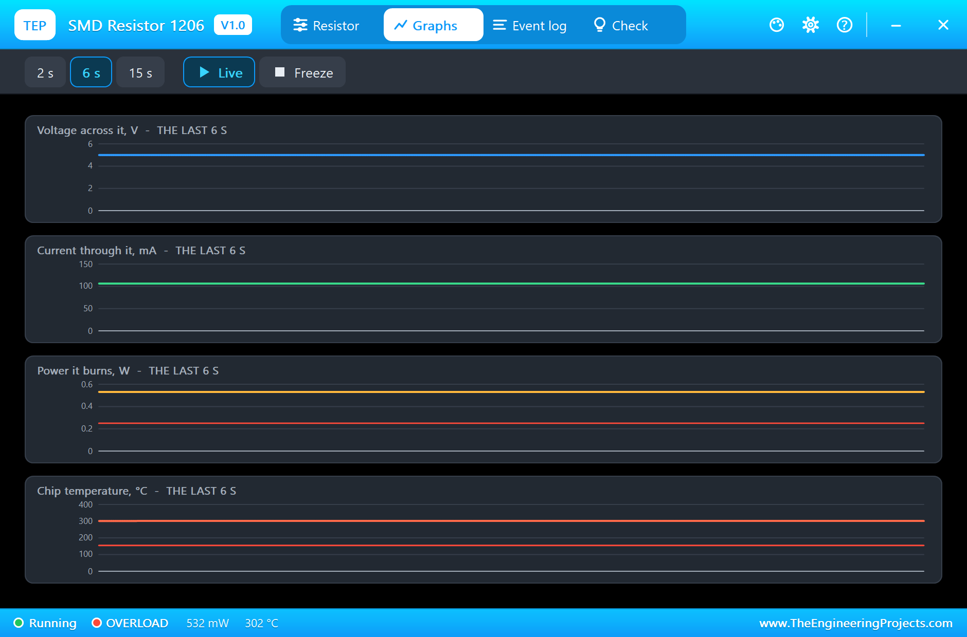
Now for the most useful lesson in the demo. R6 and R7 are both 47 ohm, both printed 470, and both have 5 V across them, so both burn exactly 532 mW. The 1206 is rated for 0.25 W, so it is overloaded more than twice. Its pop-up turns red, and its chip climbs to 302 C:
The 2512 carries exactly the same power, but it is rated for 1 W. It runs at 94 C. That is still warm, since 532 mW is just over half its rating, and the Check page will remind you that designers like to stay under half. But it is safe, and nowhere near the 155 C limit:
The Graphs tab of R6 shows its power far above the red line of its rating, and its temperature far above the red line of its 155 C limit:
The monitor confirms the divider. The codes predicted 3.40 V, and A0 read 3.41 V, the difference being one step of the converter:
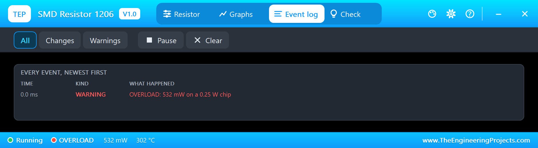
The Log and the Check Page
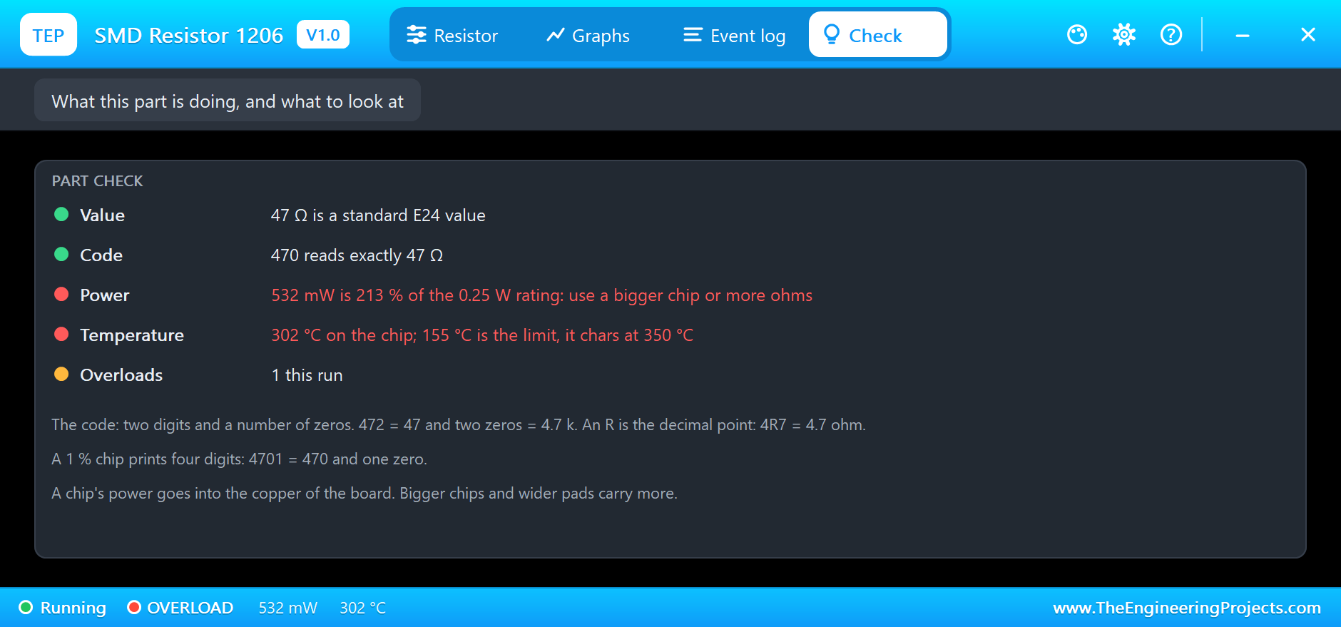
The Event log of R6 recorded the overload as soon as the power was on. The Check page sums it up: the value, the code, the power against the rating, and the temperature:
Try It Yourself
- Use the E24 chips on R1 to step its value, and watch both the code and the LED change.
- Set R5's tolerance to 1 %, and see its code turn into four digits.
- Change R6 to 100 ohm, and find out whether a 1206 can carry it.
- Leave R6 at 47 ohm but set its power rating to 0.125 W, and watch it burn out. Then click New part.
- Type 4R7 as a value, and see how a small resistance is printed.
Ideas to Extend the Demo
- Build an LED bar with a chip resistor for each LED.
- Measure a current with a low value 2512, such as 1 ohm, and the voltage across it on A1.
- Make a small ohmmeter that compares an unknown chip with a known one.
- Replace the through-hole resistors in another demo with chips of the same value.
Your Own Sketches
The demo sketch is in the zip file, and you can change it in the Arduino IDE. New to Arduino? Start with our Arduino Tutorial for Beginners. Export the compiled binary, and set the UNO's PROGRAM property to the new file. Our guide on How to get the HEX file from Arduino shows you where the file ends up.
Things to Know Before Using Real SMD Resistors
- Derate generously: keep a chip under half its rating, especially on small pads.
- Watch the voltage too: small chips have a voltage limit as well, often 50 to 200 V.
- Check the size naming: imperial and metric codes look alike but mean different parts.
- Keep them in their tape: unmarked chips that escape are almost impossible to tell apart.
- Heat both pads evenly: it prevents tombstoning.
Troubleshooting
- The code is too small to read: zoom in. A 1206 is only 3.2 mm long, at true scale.
- The stopped code differs from the value: the Check page says which Code while stopped to pick, and a run sets it for you.
- A chip turned dark and stopped conducting: it burnt out. Click New part, or use a bigger chip.
- The code shows four digits: the tolerance is set to 1 %.
- The part is not simulated:
TEPSMDRES.DLLis missing from MODELS and from the project folder.
Limitations of the Simulation
- The heat model uses a fixed path to the board; the real copper area is not taken into account.
- The EIA-96 code of small 1 % chips is not printed; the three- and four-digit codes are.
- Tolerance spread and the temperature coefficient are left out: the value is exact.
- Arduino is a name of Arduino; this library is not made or endorsed by Arduino or Labcenter.
- Tested in Proteus 8.5 in November 2026 (the demo as shipped). Proteus 7 is not supported.
So, that was all about the SMD Resistor Library for Proteus. I hope you enjoy these tiny chips, and that you can now read 472 or 4R7 at a glance, and pick the right size for the power. If you have any questions, ask in the comments and I will help you out. Till the next tutorial, take care and have fun!

Comments
0