


Rocker Switch Library for Proteus: Real KCD1 Power Switch


Hello friends, I hope you all are doing great. Today, I am going to share the new Rocker Switch Library for Proteus. Look at the back of a desktop computer, a power strip, a kettle or a bench power supply, and you will very often find the same part: a small red or black rocker switch, with a line on one side and a circle on the other. It is the classic main power switch, the first thing you press and the last thing you touch.
Rocker Switch Library for Proteus
Latest version: V1.0 (November 2026, this tutorial)
Helping Tools
- Serial Monitor Advance: a serial terminal window for the UART of your board
- Serial Monitor Expert: the serial monitor with extra debugging tools
- LCD Library for Proteus V3.0: 16x2, 20x4 and I2C LCDs to show your readings
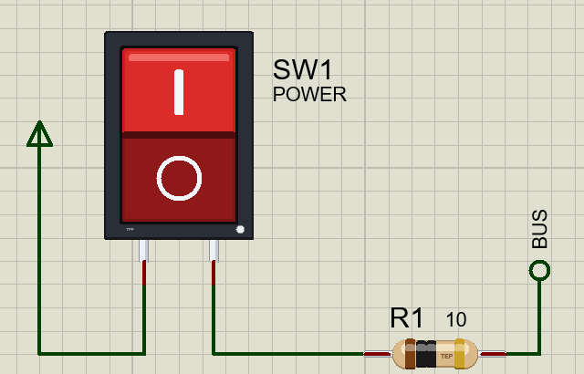
Our part is the popular KCD1 rocker, at true scale, seen from the front with its black bezel and red rocker. Click it at Run and the rocker really tips over, and the sheet keeps that position after you stop the simulation. Inside it behaves like the real thing, with a small contact resistance and true contact bounce. For the demo we have built the power switch of a small machine, and it shows two things every power switch meets: the inrush of current into an empty capacitor, and the bleeder resistor that empties it again.
NOTICE: Our team has put a lot of effort into these small parts: the bodies, the animation and the pop-ups are all our own design, and you get them free. Your feedback is the fuel that keeps us going, so please tell us what you think in the comments below or in the Rocker Switch board of our forum. And if our free libraries help you, you can buy us a coffee. So, let's get started with the Rocker Switch Library for Proteus:
What is a Rocker Switch?
A rocker switch is a switch with a wide, flat button that pivots in the middle, like a seesaw. You press one end and it goes down, while the other end comes up. Inside, a moving contact follows the rocker, so pressing one end closes the circuit and pressing the other end opens it. A spring holds the rocker firmly at either end, so it is a maintained switch: it stays where you put it.
The KCD1 is an SPST part, single pole, single throw, which is the plain on and off job. It has just two legs. When the side marked I is pressed down, the two legs are joined. When the side marked O is pressed, they are apart. The wide face makes it easy to press, even with a gloved finger, and from across a room you can see at once which side is down.
| Feature | The real part | In the library |
|---|---|---|
| Bezel | KCD1, 15 x 21 mm | 630 x 882 thou, true scale |
| Legs | two solder tabs | the same: 1 and 2 |
| Rating | about 6 A at 250 V AC, 10 A at 125 V AC | the Check page warns over 6 A |
| Contact | a few tens of milliohms | 0.02 ohm, a property |
| Action | rocks over, and stays | a click tips the rocker |
What Do I and O Mean?
The two marks are not letters. They come from an international standard for symbols on equipment, and they stand for the binary digits 1 and 0. The line means power on, and the circle means power off. When the two are combined into a single symbol, a line poking into the top of a circle, it marks a button that does both, or a standby button. Because these symbols do not depend on any language, the same switch can be sold all over the world.
Rocker, Toggle or Slide?
All three can do the same electrical job, and the choice is mostly about the hand and the panel. A rocker has the biggest face, so it is the easiest to press and to read, and it is the usual choice for a main power switch. A toggle, like the one in our Toggle Switch Library for Proteus, has a lever that you can find by feel, and it looks at home on a control panel. A slide switch sits flat on a board, and it is best for a setting you rarely change. Rockers are also made to carry far more current than a small slide switch.
Mounting a Rocker
A KCD1 does not need a nut or a screw. Its body has springy clips on the sides, and it simply snaps into a rectangular hole in the panel, about 13 by 19 mm. The bezel covers the edges of the hole, so the cut does not have to be perfect. Wires go onto the two tabs at the back, either soldered or with push-on connectors. On anything carrying more than a low voltage, the tabs must be covered, with heat-shrink tube or with insulated connectors.
The Lit Rocker
Many rockers have a small lamp inside the button, so the whole rocker glows when the power is on. Those parts have a third leg for the lamp, and on a mains switch the lamp is usually a neon bulb with its own resistor. Our part is the plain two-leg KCD1. If you want a glowing indicator in your circuit, an LED on the switched side does the same job, as our demo shows.
Inrush: the Rush of Current at Switch-On
Almost every power supply has a big capacitor right after the switch. While the power is on, it smooths the supply and keeps a little energy in store. But at the moment you switch on, that capacitor is completely empty, and an empty capacitor behaves like a short circuit. For a brief moment, a large current rushes in to fill it, far more than the circuit draws once it is running. That is called the inrush current.
Inrush matters for three reasons. It is hard on the switch contacts, because the biggest current flows at the very moment the contact is landing and bouncing. It can blow a fuse that is perfectly happy with the normal current. And it can make the supply voltage dip, upsetting other parts of a system. Large power supplies limit it with a special resistor called an NTC thermistor, which starts with a high resistance and drops as it warms up, or with a resistor that a relay bypasses once the capacitor is full.
Our demo uses the simplest version of that idea: a 10 ohm resistor in series. It sets the peak of the rush to about 5 V divided by 10 ohm, roughly half an amp, and it costs us a small voltage drop while the machine is running. The pop-up of the switch records the peak current, so you can see the rush with your own eyes.
The Bleeder Resistor
Now think about the opposite moment. You switch off, but the big capacitor is still full of charge, and it has nowhere to go. In a small circuit, that just means an LED that fades instead of switching off at once. In a large power supply, it can mean a capacitor that stays charged to a dangerous voltage long after the plug is pulled. The fix is a bleeder resistor across the capacitor. It wastes a tiny current all the time, and in return it empties the capacitor in a known time after the power goes. Safety standards for mains equipment ask for exactly this.
Choosing a bleeder is a trade. A small resistor empties the capacitor quickly, but it wastes more power while the machine runs. A big one wastes almost nothing, but it takes longer. The time to empty is set by the resistor times the capacitance. In our demo that is 1k times 1000 uF, which is one second.
Switching DC Loads
Like the toggle, a rocker carries a lower rating for direct current than for alternating current, because an arc on DC does not go out by itself at a zero crossing. A rocker rated for many amps on the mains may be rated for only a few amps on 12 V DC, and less again for a motor. For a car or a battery system, look for a rocker that is made and marked for DC.
Features of the Rocker Switch Library for Proteus
- The real look, at true scale: the black bezel, the red rocker with its I and O, and two legs, with our small TEP signature.
- Click to press: a click on the switch tips the rocker over, at Run.
- It stays where you leave it: the position stays after Stop, and you can pick it while stopped too.
- True contact behaviour: a small resistance closed, and real contact bounce as it lands.
- The peak current: the pop-up records the largest current the contact has carried, so an inrush cannot hide.
- A true analog part: it works with any circuit, not only with logic.
- A pop-up for every part: click the small dot at Run for the contact, eight live values, graphs, an event log and a check page.
- A complete package: about 2.1 MB with the library, our Arduino UNO V4.0, the demo's resistors, LED and capacitor and the demo, without the source code of the models.
The Rocker Switch in Proteus
The device is SWITCHROCKERTEP in TEPROCKER.LIB, under Switches and Relays, Switches, with the prefix SW and the model TEPROCKER.DLL. Search SWITCHROCKER in Pick Devices. The pins are 1 and 2.
Click It, or Open It
A click anywhere on the bezel or the rocker tips the switch over while the simulation runs. A click on the small round dot in the corner of the bezel opens the pop-up instead, and leaves the switch alone.
The Properties
| Property | What it does |
|---|---|
| Contact resistance, ohm | the closed contact, 0.02 ohm by default |
| Contact bounce, ms | how long it chatters, 3 ms by default; 0 is a perfect contact |
| Position while stopped | OFF or ON: where it starts |
Download Rocker Switch Library for Proteus
Click the button below to download Rocker-Switch-Library-for-Proteus-v1.0.zip (about 2.1 MB, without the source code of the models):
Rocker Switch Library for Proteus V1.0- README.txt: installation, the demo, the properties, troubleshooting and the limits.
- Proteus Library Files:
TEPROCKER.LIB,TEPRESISTOR.LIB,TEPLED5MM.LIB,TEPELECTRO.LIBand ourArduinoV4TEP.LIB. - Proteus Model Files:
TEPROCKER.DLL,TEPRESISTOR.DLL,TEPLED5MM.DLL,TEPELECTRO.DLLandTEPARDUINO.DLL. - Arduino Code: the demo sketch.
- Proteus Simulation: the demo project, its HEX file and copies of the DLLs.
No Proteus yet? Read How to Download and Install Proteus 7 and 8. New to libraries? Follow How to Install a New Library in Proteus.
How to Install Rocker Switch Library for Proteus
- Close Proteus and extract the whole zip file, for example to your Desktop.
- Copy the files from Proteus Library Files into the LIBRARY folder of Proteus.
- Copy the files from Proteus Model Files into the MODELS folder.
- Delete
TEPROCKER.IDXfrom the LIBRARY folder if it is there. - Start Proteus, press P and search for SWITCHROCKER.
Demo: The Power Switch of a Small Machine
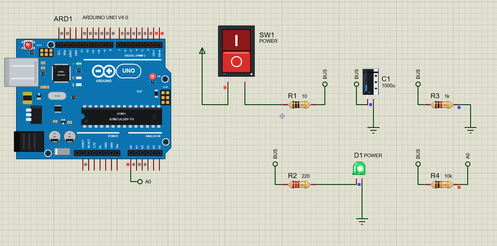
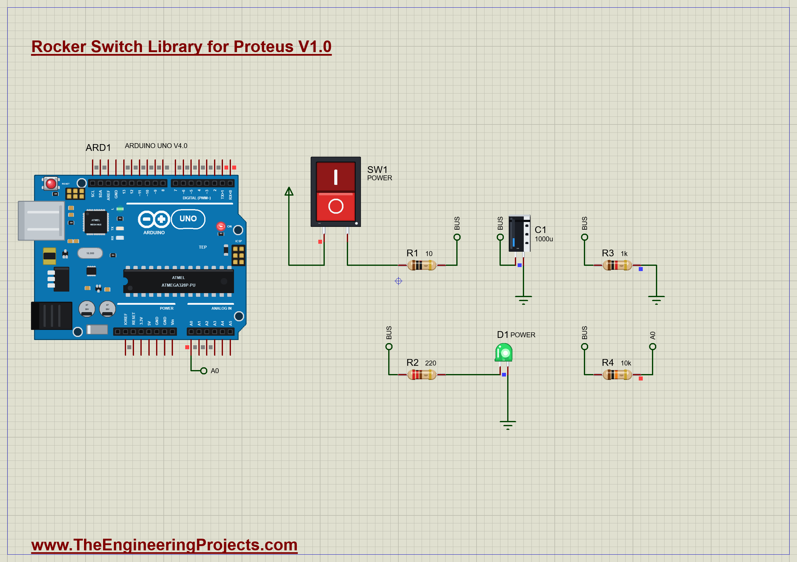
The demo is a small power bus, the kind found inside many gadgets. SW1 is the main switch. R1 is the soft start, C1 the store, R3 the bleeder, and the green LED D1 shows when the bus is up. Open Rocker-Switch-Power-Bus-ArduinoUnoV4.pdsprj. It runs on our Arduino UNO Library for Proteus V4.0, with its built-in monitor, the same window as our TEP Serial Monitor Advance for Proteus. The resistors are from our Resistor Library for Proteus, the LED from our 5 mm LED Library for Proteus and the capacitor from our Electrolytic Capacitor Library for Proteus.
The Arduino supplies the 5 V and keeps a stopwatch, nothing more. It does not switch the power: only your click on the rocker does that.
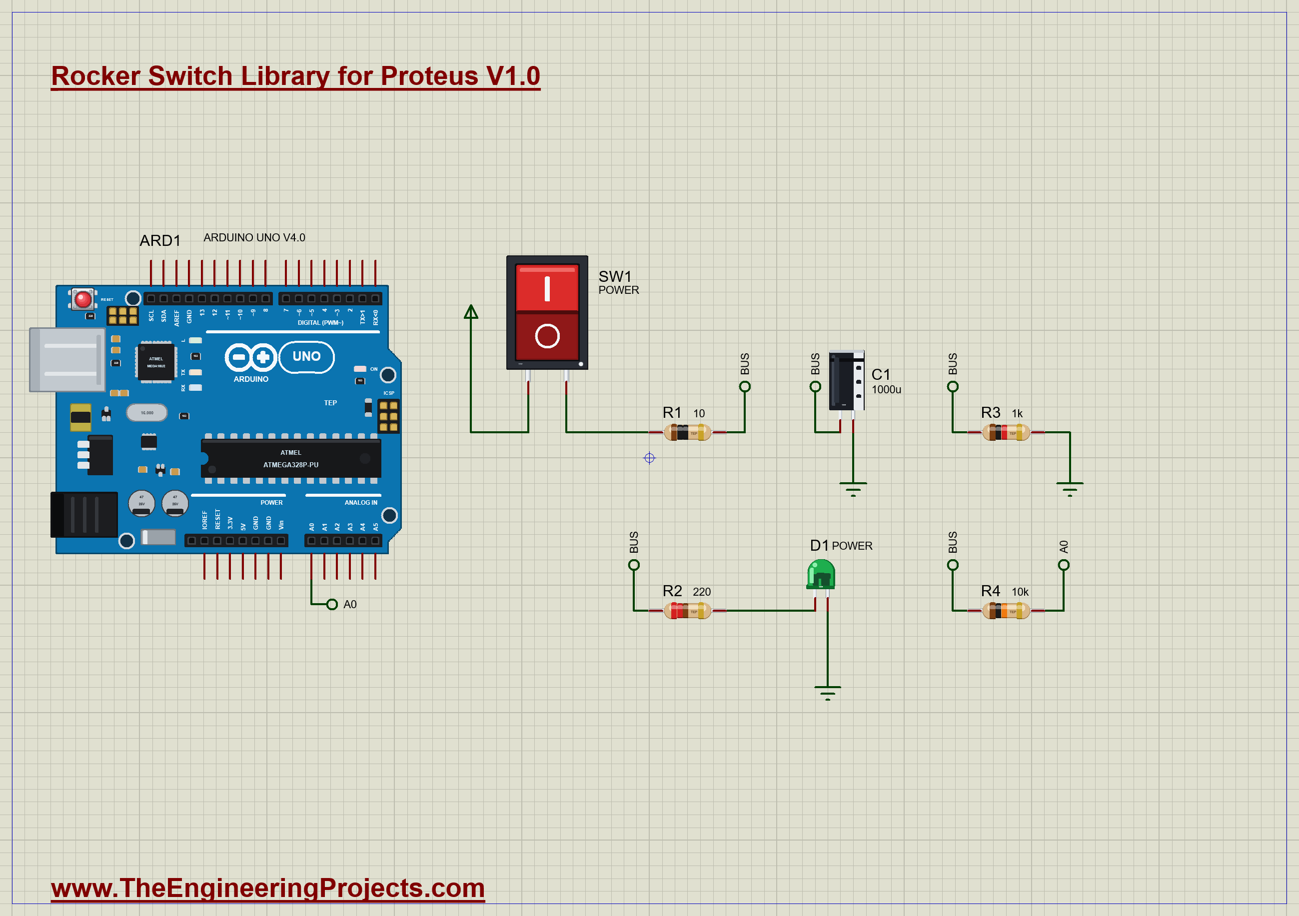
| Part | Connection | Job |
|---|---|---|
| SW1 | 1 to +5V, 2 to R1 | the main power switch |
| R1 | 10 ohm, SW1 to the BUS | the soft start |
| C1 | 1000 uF, BUS to GND | the store |
| R3 | 1k, BUS to GND | the bleeder |
| D1 and R2 | BUS, through 220 ohm, to GND | the power light |
| R4 | 10k, BUS to A0 | lets the sketch watch the bus |
Timing the Bus
The sketch reads A0 in the main loop and moves through four states: down, rising, up and falling. When the reading first climbs above about 0.5 V, it starts a stopwatch. When the bus reaches about 4.4 V, it calls the bus up and prints the time:
    case BUS_RISING:
      if (bus > UP_LEVEL) {
        state = BUS_UP;
When the reading drops below 4.4 V again, the switch has opened, and the stopwatch restarts until the bus is below 0.5 V. Notice the names: RISING and FALLING are already taken by the Arduino core for interrupts, so our states carry a BUS_ prefix:
    case BUS_UP:
      if (bus < UP_LEVEL) { state = BUS_FALLING; startedAt = millis(); }
Run the Demo
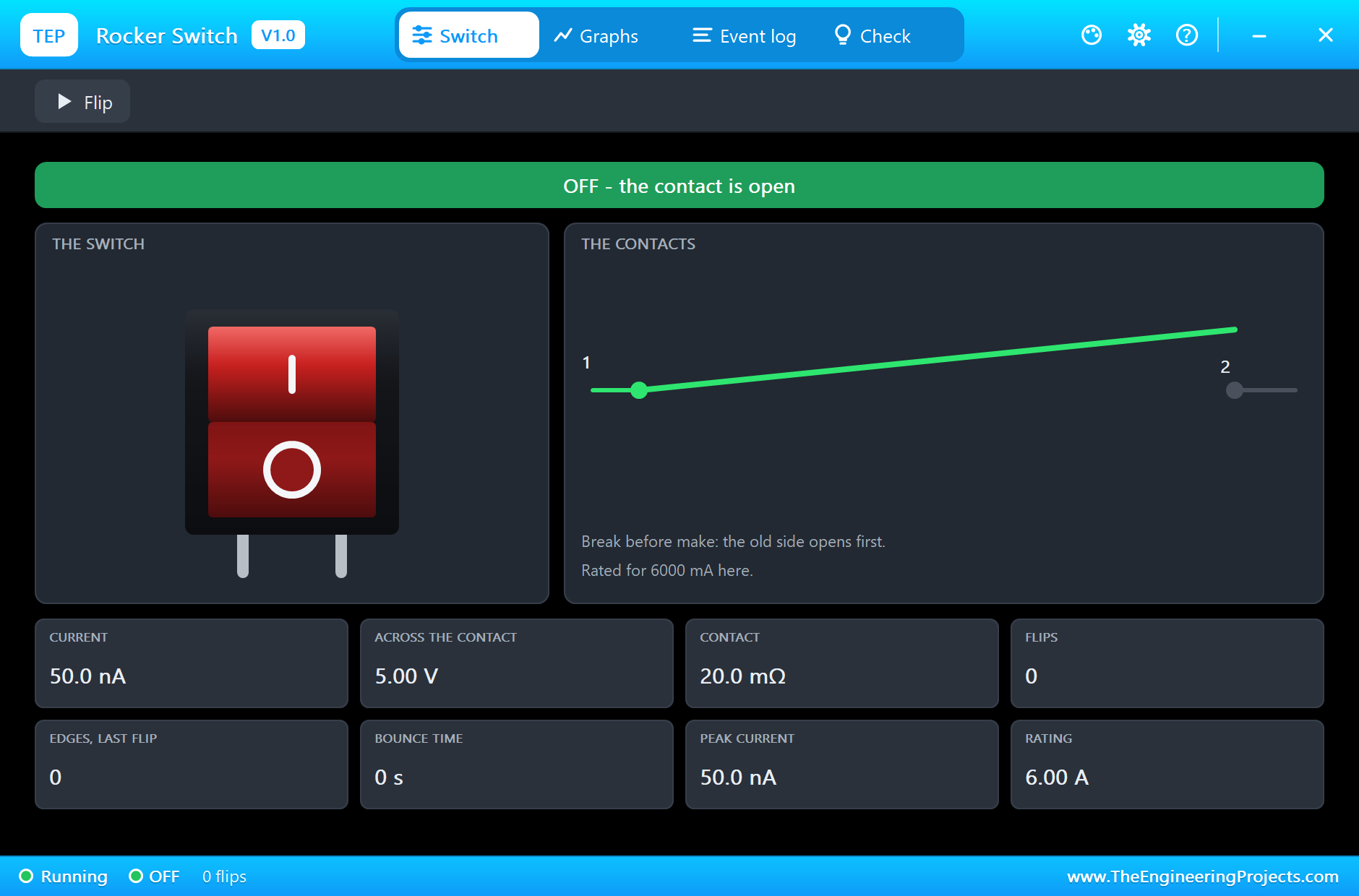
Press Run. The rocker is on O, so the bus is at 0 V and the LED is dark. Click the small dot on SW1 to open its pop-up. The contact is drawn open, and nothing flows:
Switch On
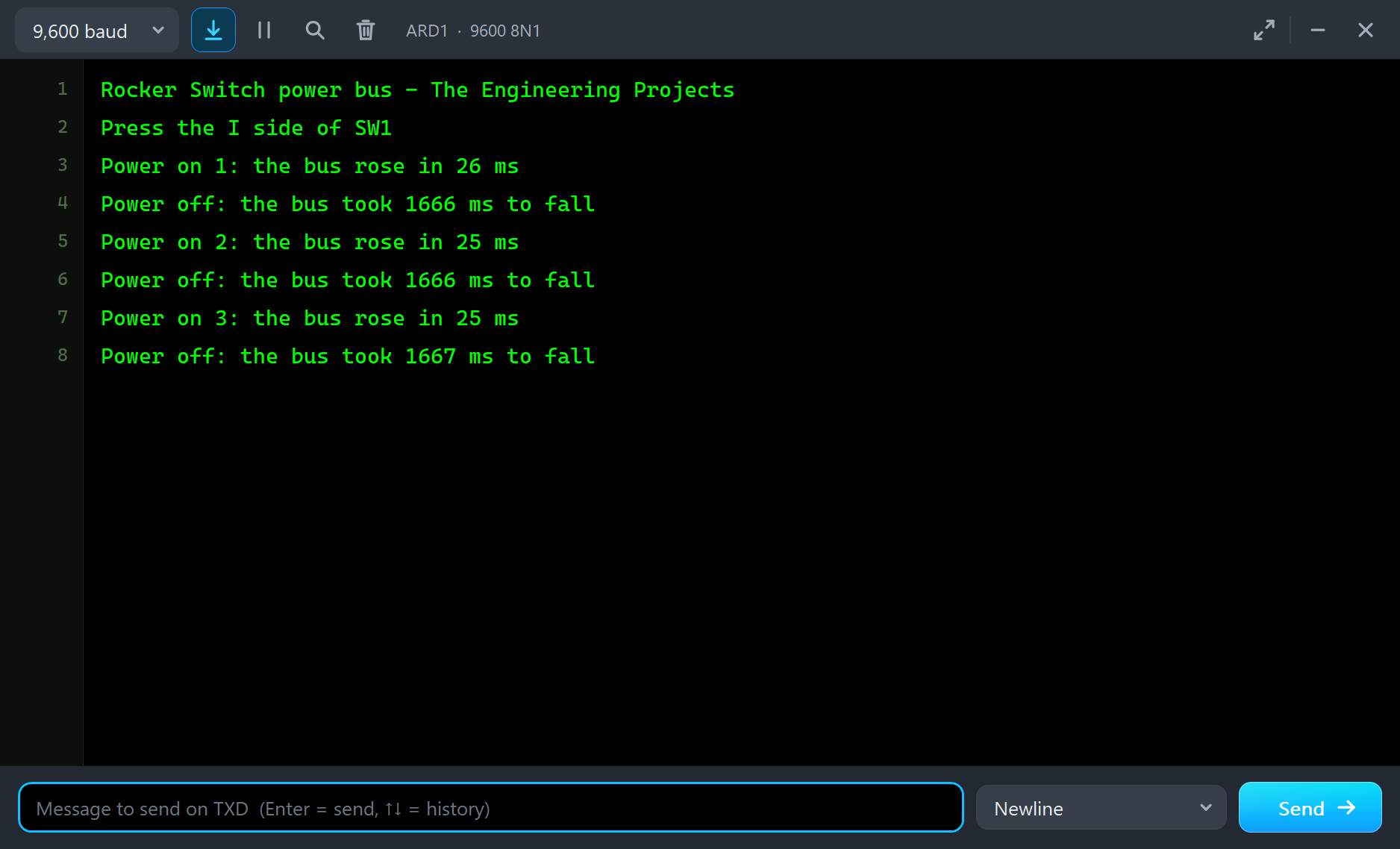
Click the rocker. It tips over to I, the LED lights, and the monitor reports that the bus rose in about 25 ms. Here is the complete circuit, truly running:
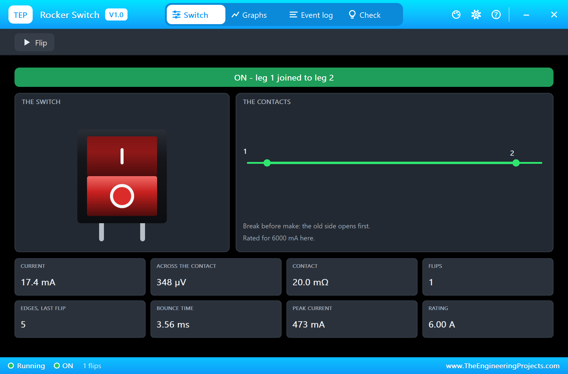
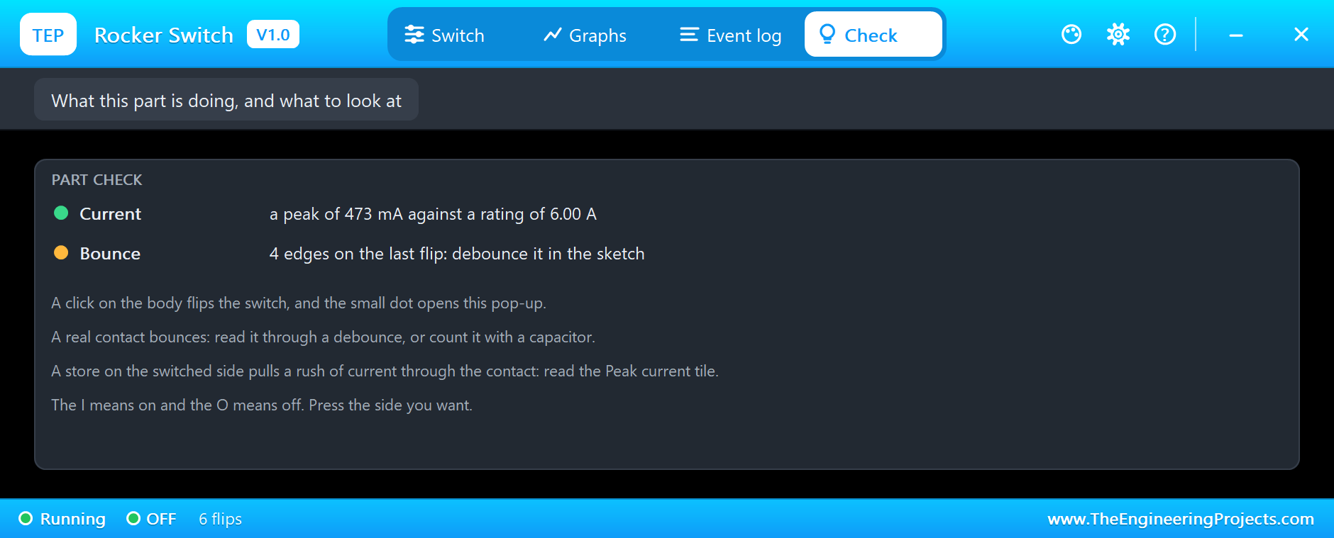
Now look at the pop-up. The steady current is 17.4 mA: the LED takes 12.6 mA and the bleeder the rest. But the Peak current tile says 473 mA. That is the inrush, the moment the empty capacitor was filled through R1, and it is more than twenty times the running current. It is still far below the 6 A rating, thanks to R1:
Switch Off
Click the rocker again. The contact opens at once, and the current falls to zero. But the bus does not drop at once. The capacitor keeps it up, and the LED fades out as the charge drains away through the bleeder. The Graphs tab shows it well. The voltage across the open contact climbs smoothly towards 5 V, because one side stays on 5 V while the other side, the bus, slowly falls:
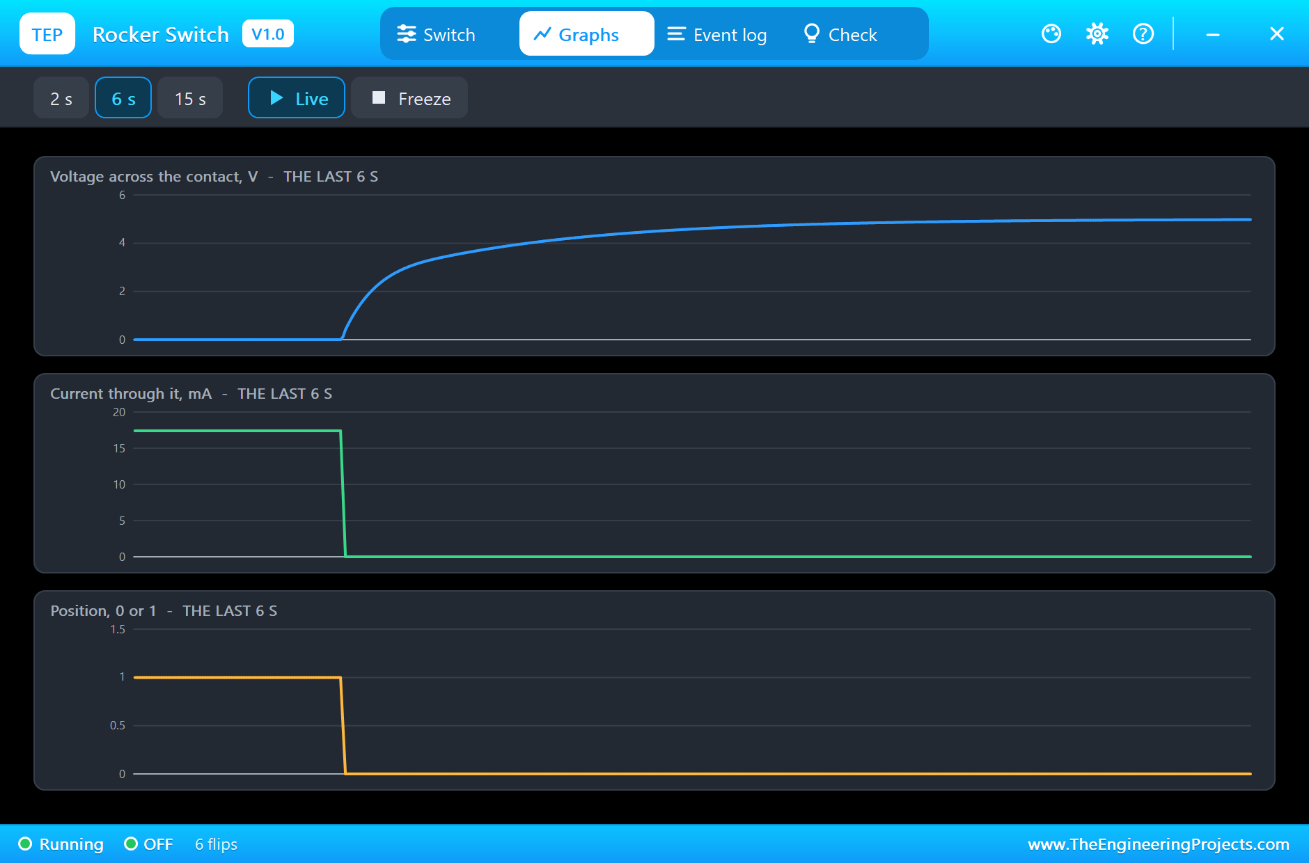
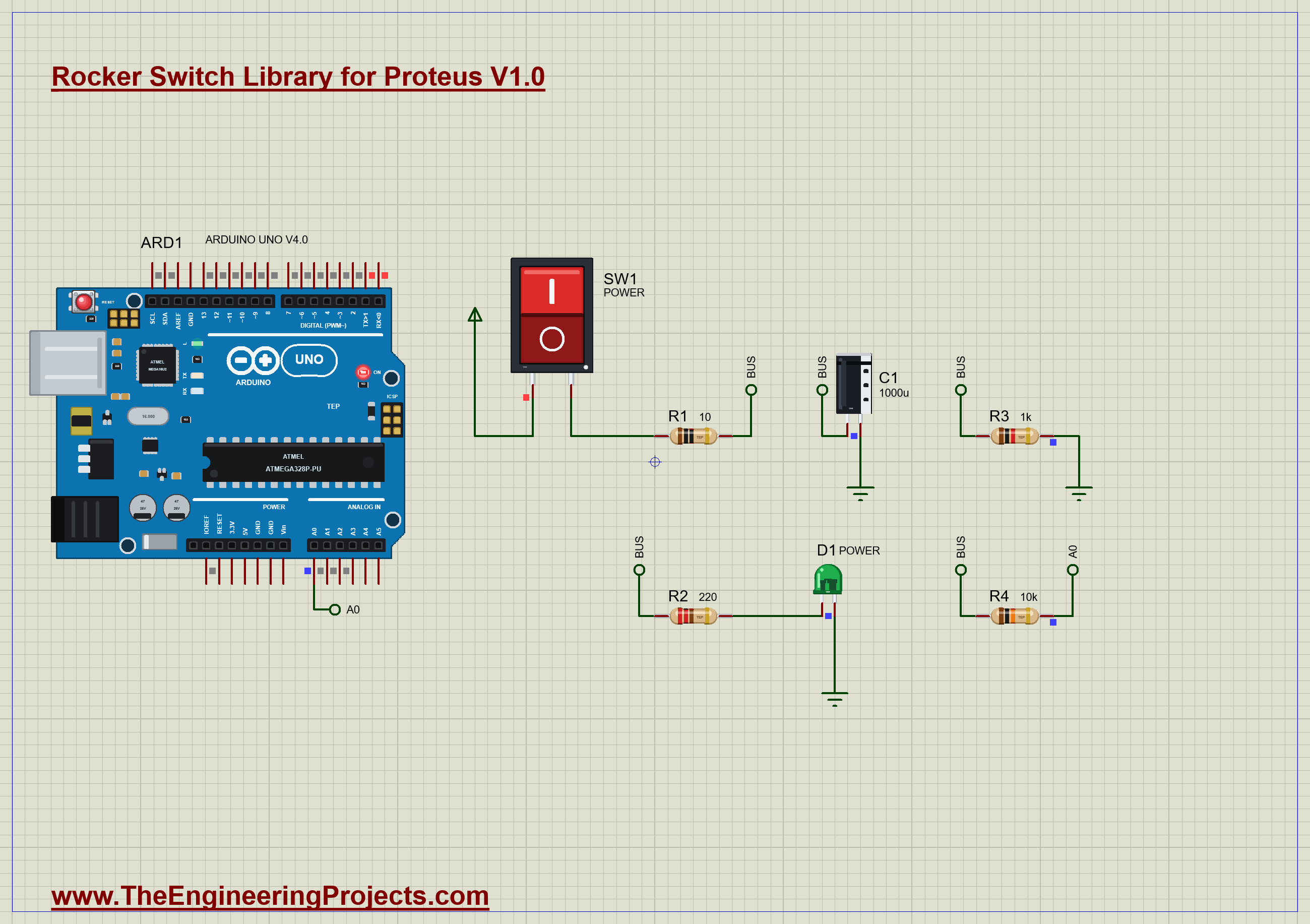
The monitor puts numbers on all of it. In this run the bus rose in 25 or 26 ms each time, and took 1666 or 1667 ms to fall below 0.5 V. That is very close to what the resistor and capacitor predict:
The Log and the Check Page
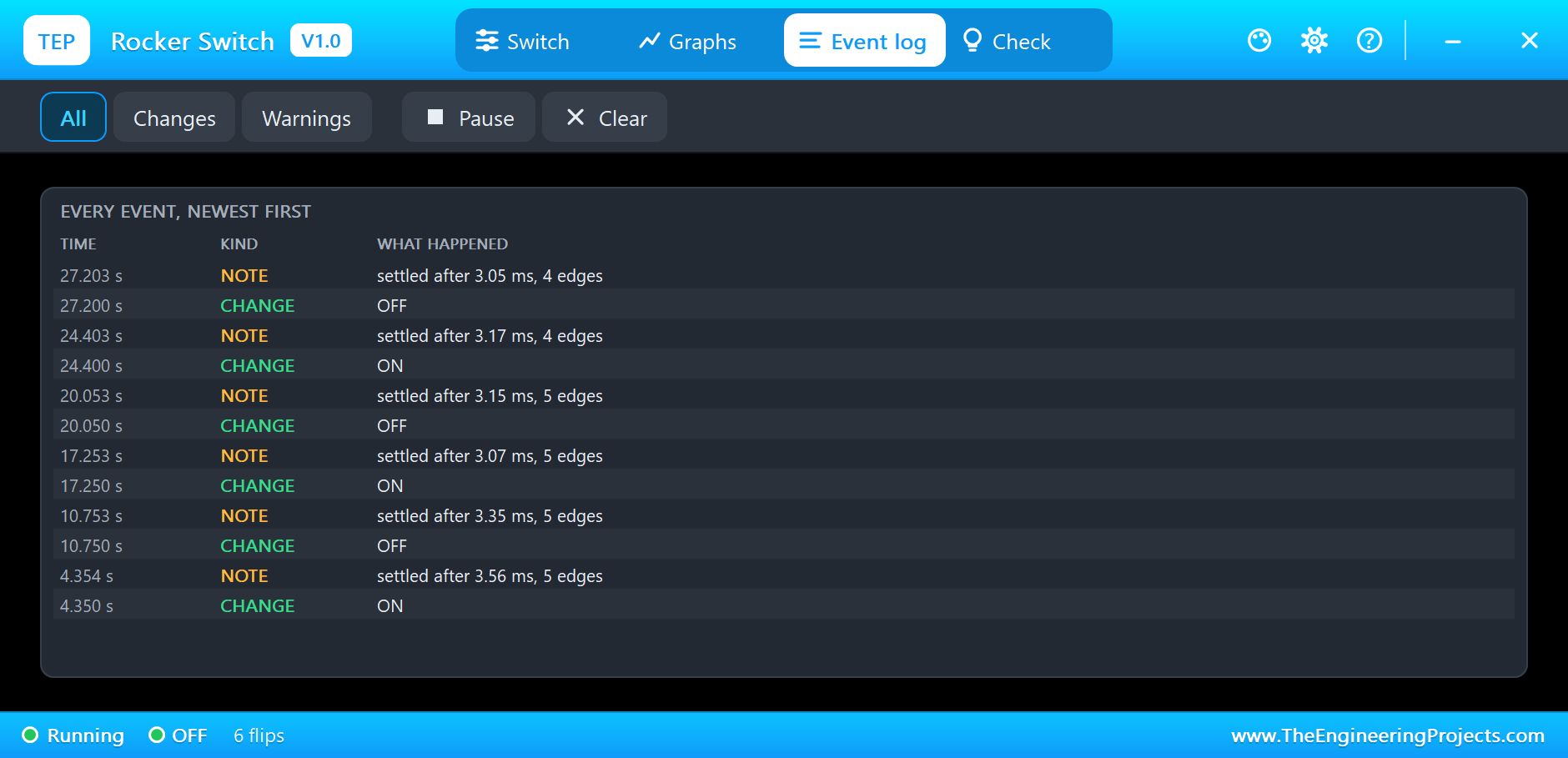
The Event log writes down each press and how the contact settled. Here, every press settled in 3 to 3.6 ms, with 4 or 5 edges. The Check page compares the peak current with the rating, and reminds you that the contact bounces:
Try It Yourself
- Take R1 out of the circuit by joining its two ends, then watch the Peak current tile and read the Check page.
- Change R3 to 10k, and see how much longer the bus takes to fall.
- Remove R3 completely, and watch the LED hold the bus up for a long time.
- Change C1 to 100 uF, and compare the rise and fall times with the ones above.
- Set the contact bounce to 0 ms, and compare the Event log.
Ideas to Extend the Demo
- Make the sketch count how many times the machine has been switched on, and keep the total in EEPROM.
- Add a buzzer that beeps once when the bus is up.
- Put a second rocker in series as a safety interlock, so both must be on.
- Measure the bus on a second analog pin before and after R1, and print the drop across it.
Your Own Sketches
The demo sketch is in the zip file, and you can change it in the Arduino IDE. New to Arduino? Start with our Arduino Tutorial for Beginners. Export the compiled binary, and set the UNO's PROGRAM property to the new file. Our guide on How to get the HEX file from Arduino shows you where the file ends up.
Things to Know Before Using a Real Rocker Switch
- Check both ratings: the current and the voltage go together, and DC is far harder on a contact than AC.
- Pick the right cut-out: the clips only hold in a hole of the right size, in a panel of the right thickness.
- Cover the tabs: use insulated push-on connectors or heat-shrink tube, especially on the mains.
- Leave mains wiring to a qualified person: a power switch for the mains belongs in a proper, earthed box.
- Plan for the inrush: a big capacitor or a motor after the switch pulls a rush, so size the switch and the fuse for it.
Troubleshooting
- A click opens the pop-up: you clicked the small dot. Click the rocker to tip it over.
- The LED stays lit after OFF: that is C1 emptying through R3 and the LED, as it should.
- The bus never falls to 0 V: check R3, the bleeder.
- The Peak current tile is very high: a capacitor straight after the switch pulls a rush. Add a few ohms in series.
- The sketch does not compile: a state named
RISINGorFALLINGclashes with the Arduino core. Keep the prefix. - The part is not simulated:
TEPROCKER.DLLis missing from MODELS and from the project folder.
Limitations of the Simulation
- The bounce follows a fixed pattern, with a real-looking spread, not a measured one.
- The arc on a heavy load, wear and a lamp inside the rocker are left out.
- The rating is a warning on the Check page, for the current only: a real contact would pit or weld.
- Arduino is a name of Arduino; this library is not made or endorsed by Arduino or Labcenter.
- Tested in Proteus 8.5 in November 2026 (the demo as shipped). Proteus 7 is not supported.
So, that was all about the Rocker Switch Library for Proteus. I hope you enjoy pressing that little red rocker, and that the next time you switch on a power supply, you think of the rush into its capacitor and the quiet bleeder that empties it afterwards. If you have any questions, ask in the comments and I will help you out. Till the next tutorial, take care and have fun!

Comments
0