


Bi-Colour LED Library for Proteus: Two Legs, Three Colours


Hello friends, I hope you all are doing great. Today, I am going to share the new Bi-Colour LED Library for Proteus. Battery chargers, routers and coffee machines all have a little status light that shows red, then green, then amber. Often that is one LED with just two legs. How can two legs give you three colours? The answer is one of the neatest tricks in the whole LED family, and it needs nothing more than the direction of the current.
Bi-Colour LED Library for Proteus
Latest version: V1.0 (November 2026, this tutorial)
Helping Tools
- Serial Monitor Advance: a serial terminal window for the UART of your board
- Serial Monitor Expert: the serial monitor with extra debugging tools
- LCD Library for Proteus V3.0: 16x2, 20x4 and I2C LCDs to show your readings
Our part is the two-legged 5 mm bi-colour LED, at true scale, with a milky dome. Inside it, a red die and a green die sit back to back. Send the current one way and it glows red. Send it the other way and it glows green. Swap it fast enough and your own eye mixes the two into yellow, and the colour really does change on your Proteus sheet. For the demo, two Arduino pins drive one LED as a complete status light.
NOTICE: Our team has put a lot of effort into these small parts: the bodies, the animation and the pop-ups are all our own design, and you get them free. Your feedback is the fuel that keeps us going, so please tell us what you think in the comments below or in the Bi-Colour LED board of our forum. And if our free libraries help you, you can buy us a coffee. So, let's get started with the Bi-Colour LED Library for Proteus:
What is a Bi-Colour LED?
A bi-colour LED holds two LED dies in one dome. In the two-legged kind, the dies are wired back to back, also called anti-parallel: the anode of each is joined to the cathode of the other. An LED only conducts one way, so at any moment only one of the two can light. Which one lights depends on which leg is more positive.
This is different from a three-legged bi-colour LED, which has a shared cathode and one leg for each colour, more like a smaller version of our RGB LED Library for Proteus. The three-legged kind can show both dies at once with no tricks, but it needs an extra leg and a pin. The two-legged kind saves one leg, and that is why it is so common on small products.
| Feature | The real part | In the library |
|---|---|---|
| Dome | 5 mm, milky | 210 thou, true scale |
| Legs | two, 2.54 mm apart | A and B, 100 thou apart |
| Red forward voltage | about 2 V | 2.0 V, a property |
| Green forward voltage | about 2.2 V | 2.2 V, a property |
| Current | 20 mA, 30 mA at most | the same |
Two Legs, Three Colours
Here is how the direction picks the colour. With leg A more positive than leg B, the current goes through the red die, and the green die blocks. Reverse the supply, and the green die conducts while the red die blocks. So a single wire pair carries the choice of colour in its polarity. Some of these parts are used across a DC motor or a battery connection for that very reason: the colour shows you which way the current is flowing.
| Pin D8 | Pin D9 | Current | You see |
|---|---|---|---|
| HIGH | LOW | A to B | red |
| LOW | HIGH | B to A | green |
| LOW | LOW | none | off |
| swapping fast | swapping fast | both ways in turn | yellow or amber |
The Third Colour
Yellow is not a real state of the part at all. Only one die is ever lit. But if you swap the direction faster than the eye can follow, roughly more than 50 times a second, your brain blends the red and green flashes. This is called persistence of vision, and it is the same effect that turns the still pictures of a film into smooth movement. You see one steady colour, and it looks yellow, because our eyes make yellow from red and green light. Your TV does exactly the same trick.
It gets better. The colour depends on how the time is shared. Give red 80 % of each cycle and green 20 %, and the mix slides towards amber. Give green the larger share, and it slides towards lime. So with one small part and two pins, you can have a whole small range of colours, not just three.
One Resistor is Enough
An RGB LED needs a resistor for each colour, as you have seen. A two-legged part needs only one, because only one die conducts at any moment. Work it out from the lower forward voltage, so that neither die can be overdriven: (5 - 2.0) / 0.02 is 150 ohm, the value in our demo. The green die has a slightly higher forward voltage, so it gets slightly less current. To learn more about series resistors, see our 5 mm LED Library for Proteus.
Which Colour is Which?
On a real part, the legs are often the same length, and nothing tells you which one is red. So test it: with a 3 V coin cell and a resistor, one way round gives red. Mark that leg. Our symbol names the two legs A and B, and current from A to B gives red.
Where Are They Used?
Look at the chargers around your home. Red for charging and green for full is the classic use. Network switches use them to show the link speed. Many audio devices show green for normal and red for a clipping signal. Model railways use them on signals and across track wires, where the colour shows the direction of the train. In each case, one small part replaces two LEDs and saves a hole in the panel, and in a mass-produced product, a hole saved is real money.
Why Can Only Some Pins Do This?
Each pin must be able both to source current and to sink it, because the current flows into one pin and out of the other. Any Arduino pin can do this. The limit is about 20 mA in normal use. A pin that only pulls down, such as an open collector output, cannot light the colour that needs it to push. So on many chips, you must check that a pin is a true push-pull output before you try this.
Why Does Red Plus Green Look Yellow?
There is no yellow light at all in our demo, so why do you see it? Your eye has three kinds of colour sensor, roughly tuned to red, green and blue. True yellow light from a sodium lamp tickles both the red and the green sensors at once. Red light and green light together tickle those same two sensors in the same way, so your brain cannot tell the difference and reports yellow. This is why three colours are enough for a whole TV screen. It also explains why a mix that fools your eye may not fool a camera, which has its own sensors and its own way of sampling time.
Time-Sharing a Part
Our sketch never sends both colours at once, because it cannot. It shares time between them, and this idea is used everywhere in electronics. A clock display lights one digit at a time, so quickly that all of them seem to be on. This is called multiplexing. A sound card shares its time between two channels. Because the sharing is so fast, the average is what you notice. In our demo, the two dies each get about 8 mA on average, though the true current is 16 mA whenever a die is on. The pop-up shows both figures: the Average tiles and the Current tile.
Three Legs or Two?
If you only ever need red or green, one at a time, the two-legged part is hard to beat. But if you want a low-power yellow without an MCU, or you need to drive it from pins that cannot reverse, a three-legged part with a shared cathode is easier. Each colour then has its own pin and its own resistor, and you can leave both on with no swapping at all. Many panel indicators use that kind. The choice comes down to how many pins you can spare, and whether your pins can both push and pull.
Features of the Bi-Colour LED Library for Proteus
- The real look, at true scale: the milky dome with two small dies and two thin legs, with our small TEP signature.
- Two dies back to back: red from A to B, and green from B to A, in the analog simulator.
- It really mixes: swap it fast, and the dome on your sheet shows the mixed colour.
- Any shade: the share of each colour sets the mix, from red through amber and yellow to green.
- A live swap rate: the pop-up shows how fast the direction is changing.
- A pop-up for every part: click it at Run for the colour, the two dies, eight live values, graphs, an event log and a check page.
- A complete package: about 1.5 MB with the library, our Arduino UNO V4.0, the demo's resistor and the demo, without the source code of the models.
The Bi-Colour LED in Proteus
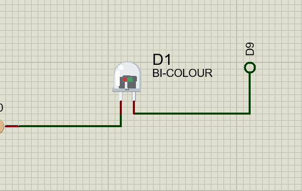
The device is LEDBICOLOURTEP in TEPBICOLOUR.LIB, under Optoelectronics, LEDs, with the prefix D and the model TEPBICOLOUR.DLL. Search LEDBICOLOUR in Pick Devices. The pins are A and B.
The Properties
| Property | What it does |
|---|---|
| Red forward voltage at 20 mA, V | 2.0 by default |
| Green forward voltage at 20 mA, V | 2.2 by default |
| Maximum current, mA | 30 by default |
Download Bi-Colour LED Library for Proteus
Click the button below to download Bi-Colour-LED-Library-for-Proteus-v1.0.zip (about 1.5 MB, without the source code of the models):
Bi-Colour LED Library for Proteus V1.0- README.txt: installation, the demo, the properties, troubleshooting and the limits.
- Proteus Library Files:
TEPBICOLOUR.LIB,TEPRESISTOR.LIBand ourArduinoV4TEP.LIB. - Proteus Model Files:
TEPBICOLOUR.DLL,TEPRESISTOR.DLLandTEPARDUINO.DLL. - Arduino Code: the demo sketch.
- Proteus Simulation: the demo project, its HEX file and copies of the DLLs.
No Proteus yet? Read How to Download and Install Proteus 7 and 8. New to libraries? Follow How to Install a New Library in Proteus.
How to Install Bi-Colour LED Library for Proteus
- Close Proteus and extract the whole zip file, for example to your Desktop.
- Copy the files from Proteus Library Files into the LIBRARY folder of Proteus.
- Copy the files from Proteus Model Files into the MODELS folder.
- Delete
TEPBICOLOUR.IDXfrom the LIBRARY folder if it is there. - Start Proteus, press P and search for LEDBICOLOUR.
Demo: One LED, Two Pins, Three Colours
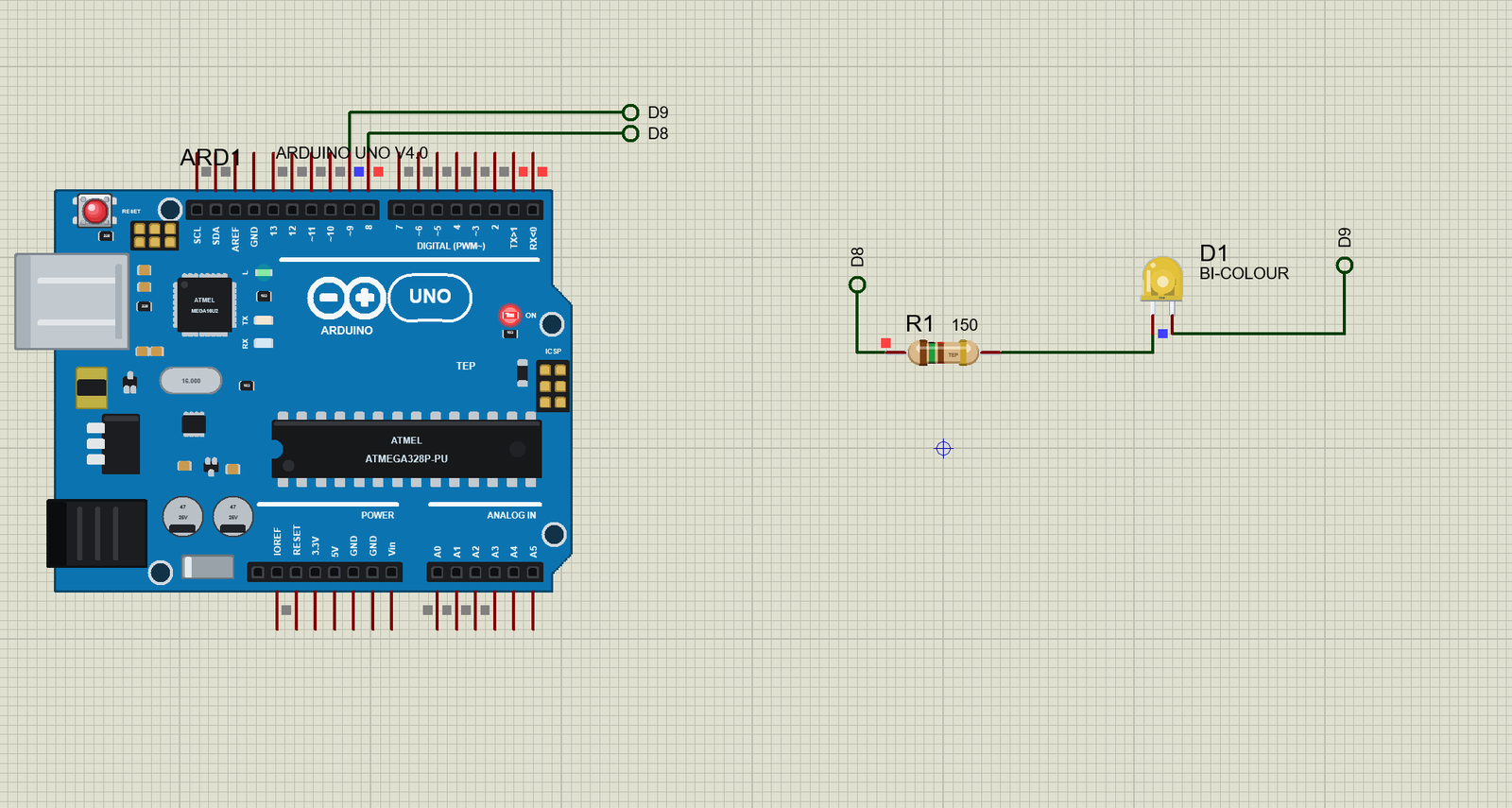
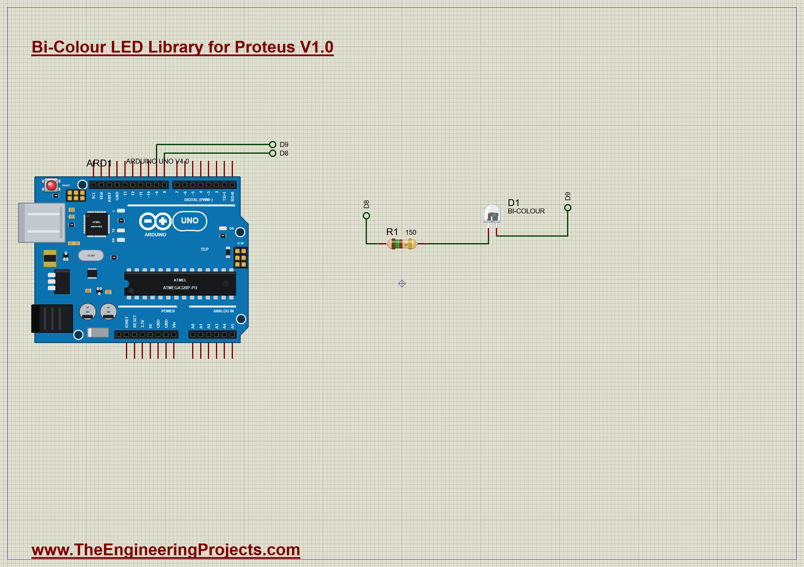
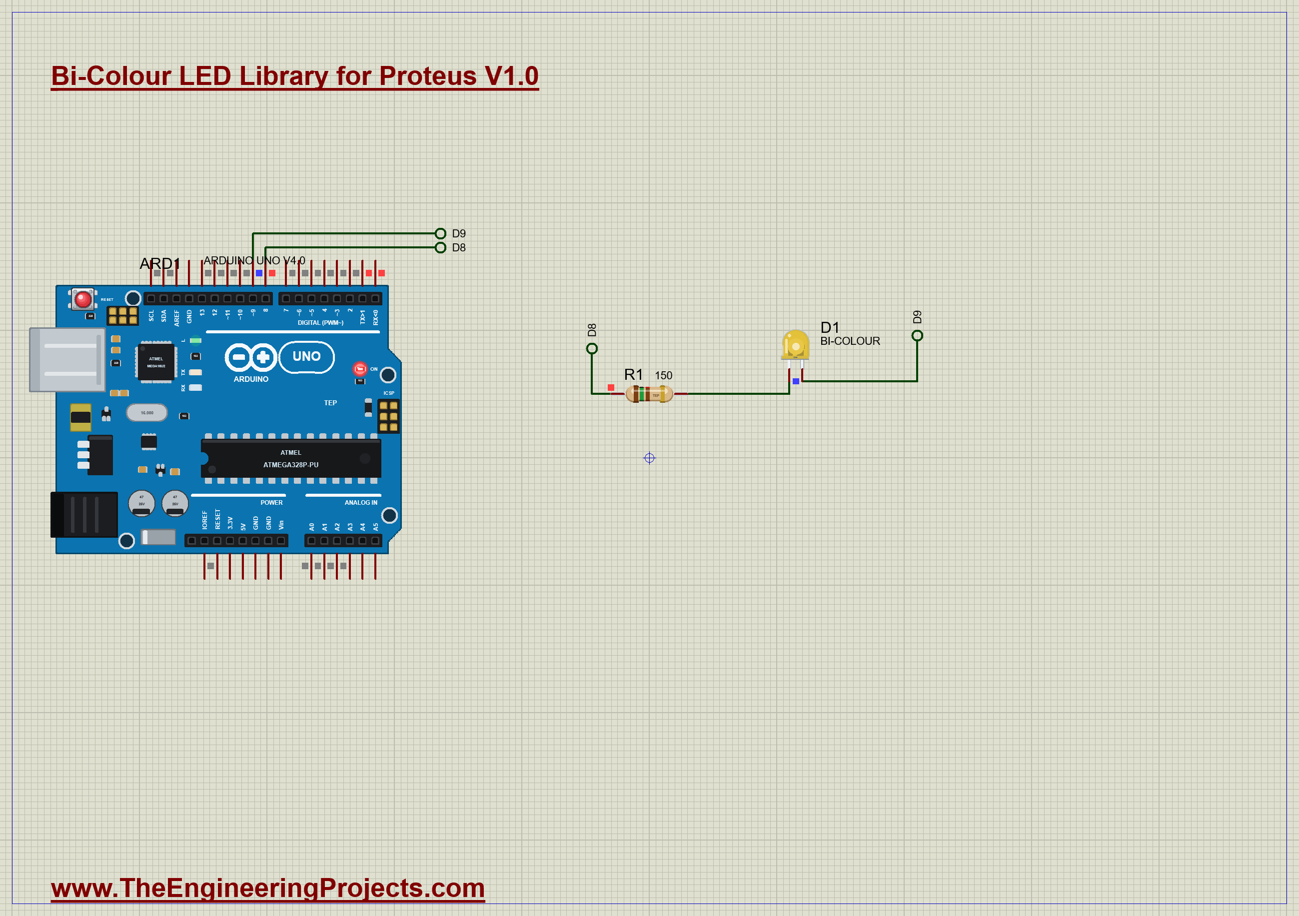
The circuit could hardly be simpler: pin D8, a 150 ohm resistor, the LED, and pin D9. Neither end goes to GND or +5V. The two pins are the supply, and they take turns. Open Bi-Colour-LED-Status-ArduinoUnoV4.pdsprj. It runs on our Arduino UNO Library for Proteus V4.0, with its built-in monitor, the same window as our TEP Serial Monitor Advance for Proteus. The resistor is from our Resistor Library for Proteus.
| Part | Connection | Job |
|---|---|---|
| R1, 150 ohm | D8 to A | limits the current, in both directions |
| D1 | A, and B to D9 | the bi-colour LED |
Mixing in the Sketch
The sketch has a cycle of 5 ms, so one red and one green take place 200 times a second. It works out where it is in the cycle, and shows red for the first part and green for the rest. The share of red decides the colour:
    unsigned long place = (micros() - cycleAt) % cycle;
    if (place < cycle * redShare / 100) red();
    else green();
The slow command runs the same code with a cycle of half a second, so that you can see what the fast one is really doing.
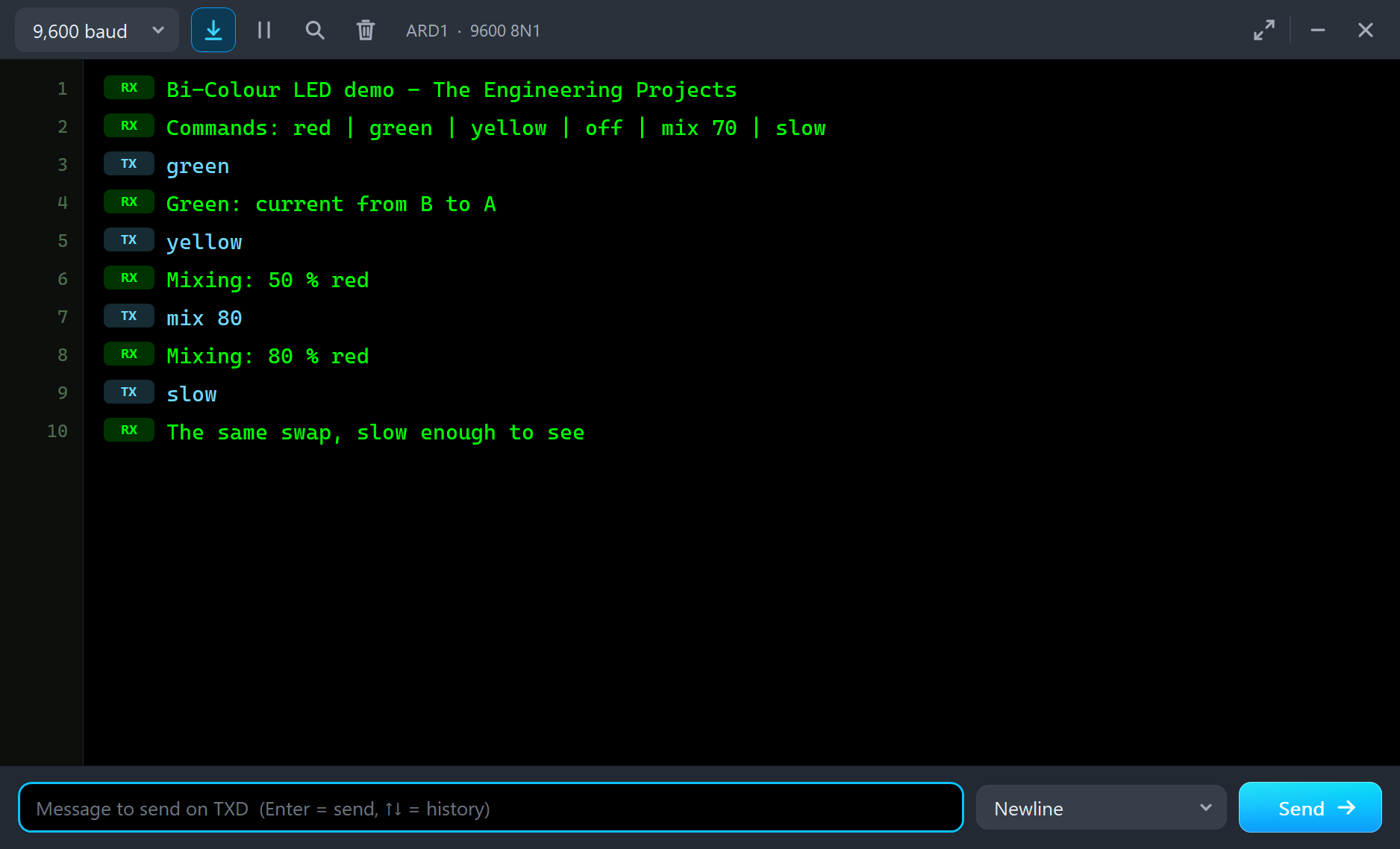
The Commands
| Type this | What happens |
|---|---|
| red | current from A to B |
| green | current from B to A |
| yellow | half and half, swapped 200 times a second |
| mix 70 | 70 % red and 30 % green |
| slow | the same swap, slow enough to see |
| off | both pins LOW |
Run the Demo
Press Run. The sketch starts with red. Click the dome to open its pop-up. The left card shows the colour, and the right card shows the two dies:
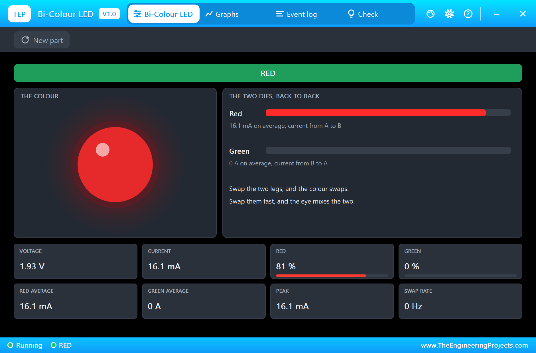
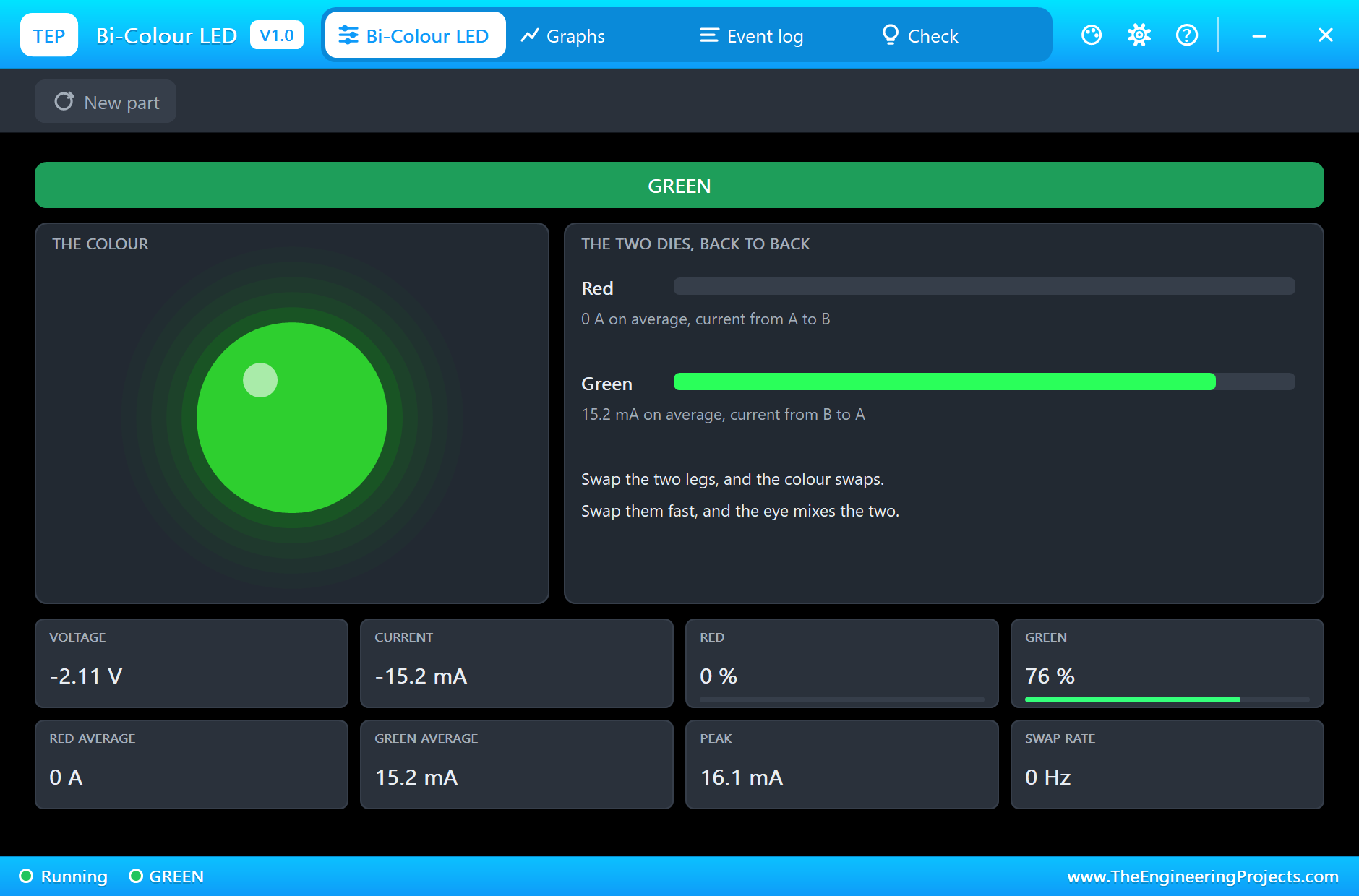
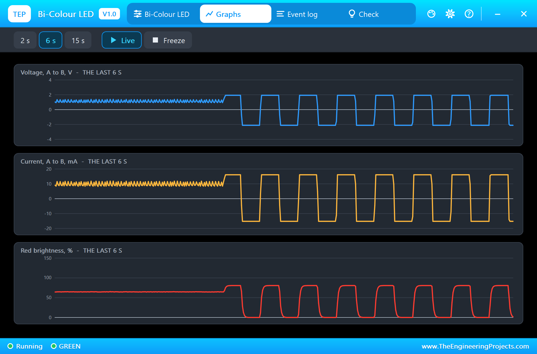
Type green in the monitor. Neither wire has moved, but the current has turned round, and the other die has taken over:
Now Make Yellow
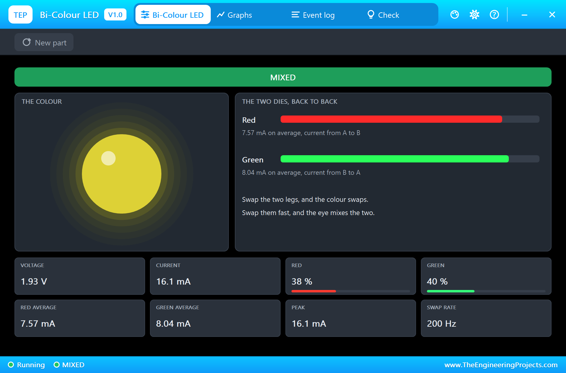
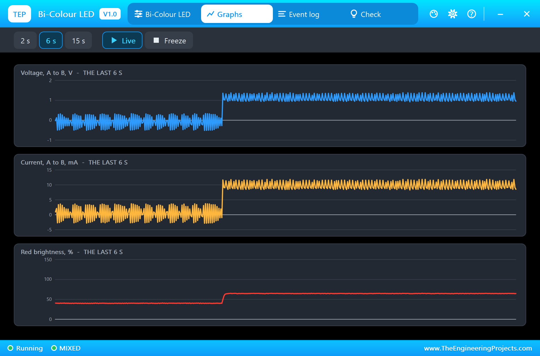
Type yellow. Each die now only gets half of the time, so both bars show a part of the full brightness, and the swap rate reads 200 Hz. There is no yellow die in the dome, yet your sheet shows yellow. Here is the pop-up, and the complete circuit truly running:
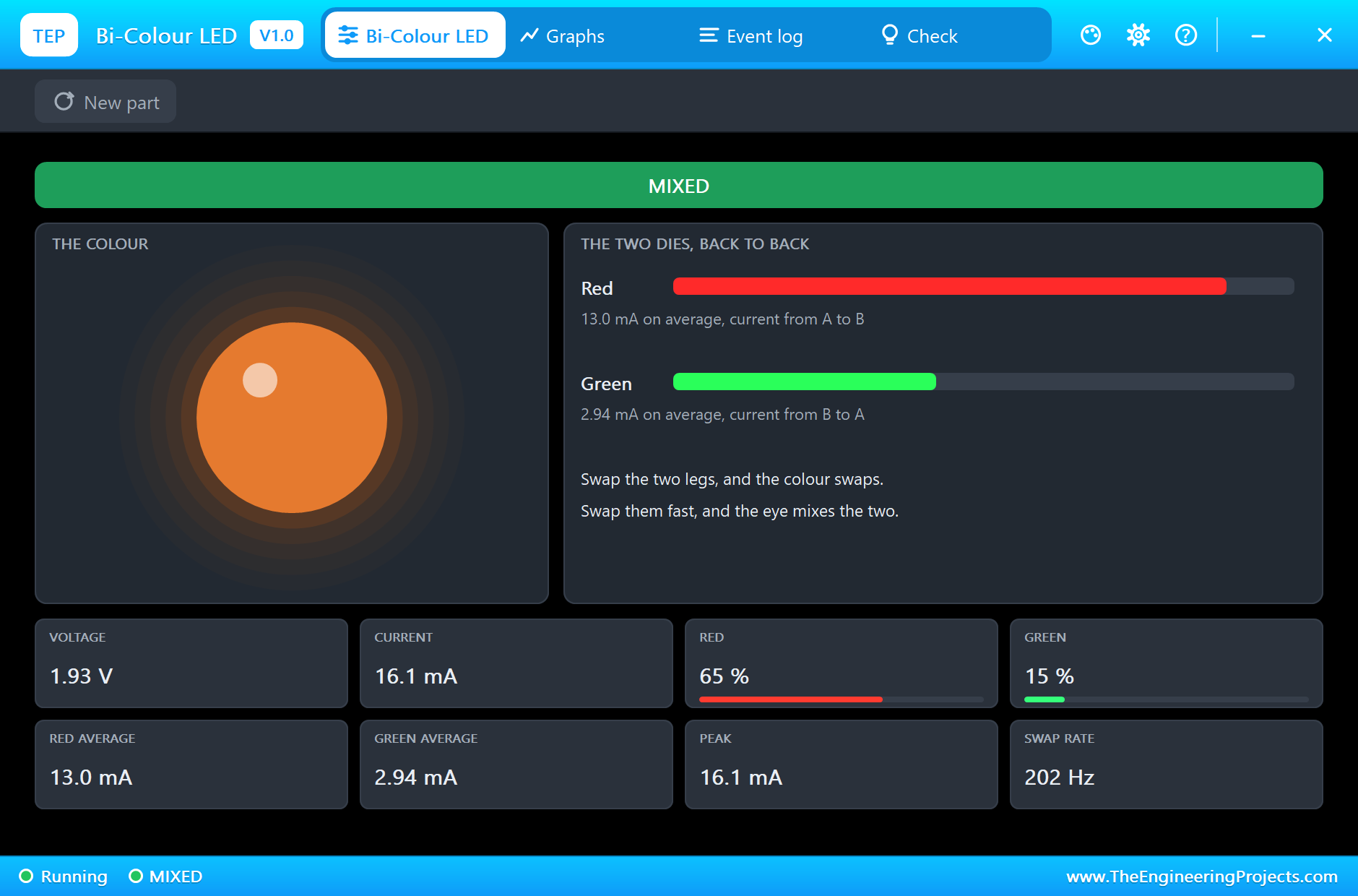
Type mix 80, and red gets 80 % of the time. The colour slides towards amber, which is the third colour most chargers use:
See What is Really Happening
The Graphs tab tells the truth. At 200 swaps a second, the current trace looks like a solid band going both ways. Now type slow, which is the same code with a cycle of half a second. You can see each swap clearly, and the LED on the sheet simply blinks red, then green:
The Log and the Check Page
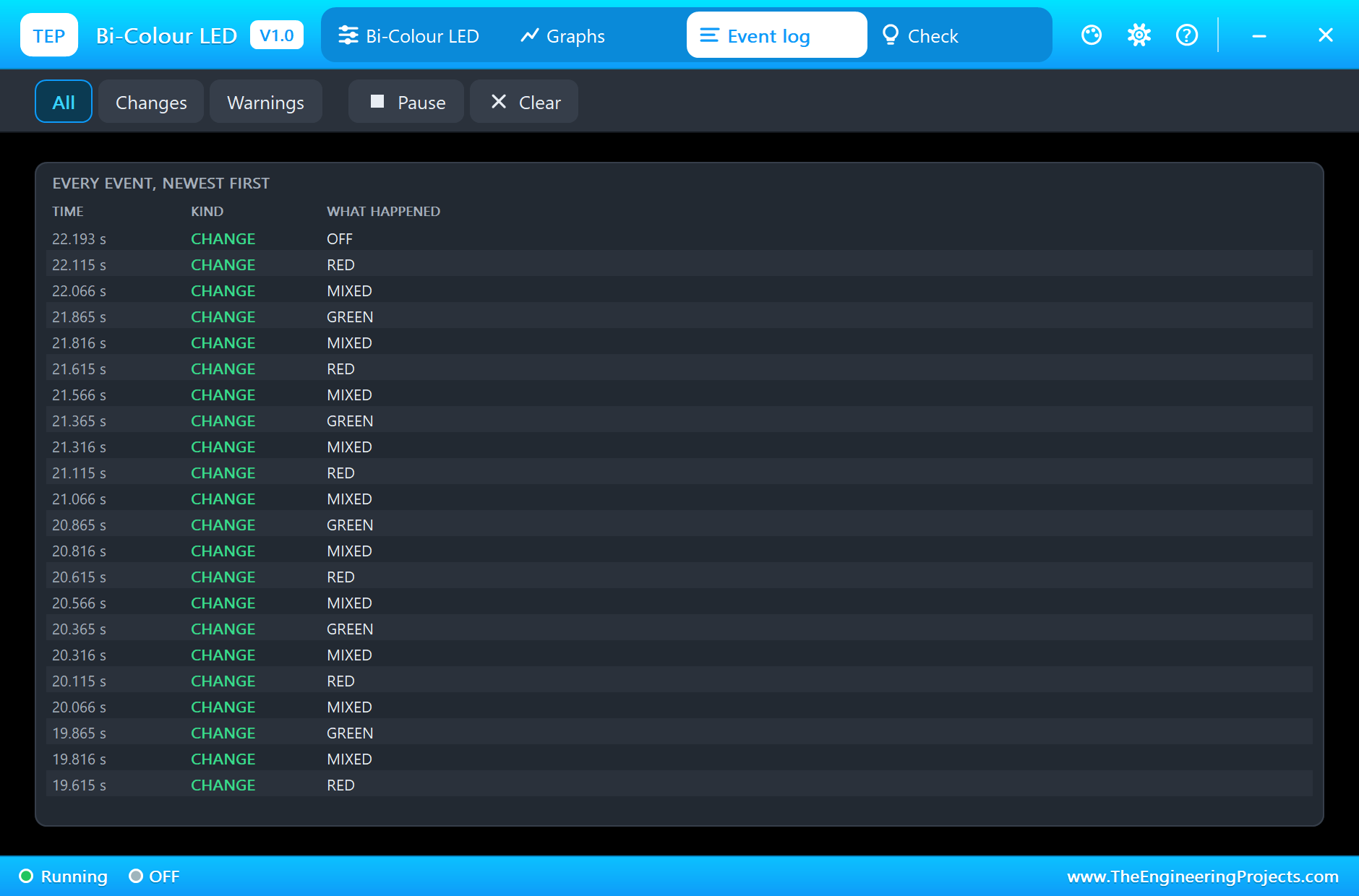
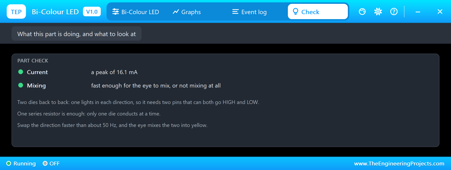
The Event log keeps each change of colour, and the Check page looks at the current, and at whether the swap is fast enough to fool the eye:
Try It Yourself
- Try mix 10, mix 50 and mix 90, and find your favourite shade.
- Change
CYCLE_USto 50000, and find the speed where the flicker begins. - Swap the D8 and D9 wires, and see every colour change places.
- Change R1 to 47 ohm, and see the Check page complain.
- Fade slowly from red to green, with the share going up by 1 each 20 ms.
Ideas to Extend the Demo
- Show a battery level: green when full, amber in the middle and red when low.
- Make a two-colour traffic signal for a model railway.
- Show the direction of a motor from its two wires.
- Show a temperature as a colour, from green to red.
Your Own Sketches
The demo sketch is in the zip file, and you can change it in the Arduino IDE. New to Arduino? Start with our Arduino Tutorial for Beginners. Export the compiled binary, and set the UNO's PROGRAM property to the new file. Our guide on How to get the HEX file from Arduino shows you where the file ends up.
Things to Know Before Using a Real Bi-Colour LED
- Use two pins that can push and pull: one end cannot simply go to GND if you want both colours.
- Find the colours first: test the part with a cell and a resistor, and mark the legs.
- Keep the swap fast: a slow swap flickers, especially on camera.
- Do not forget the resistor: it protects both dies, and the pins too.
- The dies are not equal: green often looks brighter than red, so give red a larger share for a good yellow.
Troubleshooting
- It only shows one colour: one of the two pins is not driving, or that leg is tied to GND.
- It flickers: the swap is too slow.
- The colours are the wrong way round: swap the two pins.
- BURNT OUT: use more ohms, then press New part.
- The part is not simulated:
TEPBICOLOUR.DLLis missing from MODELS and from the project folder.
Limitations of the Simulation
- The two dies are treated as equally bright, and the viewing angle is left out.
- The sheet repaints at most four times a second.
- The chips and commands of the demo change the current run only.
- Arduino is a name of Arduino; this library is not made or endorsed by Arduino or Labcenter.
- Tested in Proteus 8.5 in October 2026 (the demo as shipped). Proteus 7 is not supported.
So, that was all about the Bi-Colour LED Library for Proteus. I hope you enjoy getting so many colours from so little, and that the next time a charger turns amber, you will know what its two small dies are doing. If you have any questions, ask in the comments and I will help you out. Till the next tutorial, take care and have fun!

Comments
0