


SMD LED Library for Proteus: Real 3528 Chips and a Scanner Demo


Hello friends, I hope you all are doing great. Today, I am going to share the new SMD LED Library for Proteus. The round 5 mm LED is what we all learn with, but look inside any modern product and you will hardly find one. Phones, keyboards, TV backlights and LED strips all use tiny flat chips that sit directly on the board. These are surface mount LEDs, and the most familiar of them is the little white square called a 3528.
SMD LED Library for Proteus
Latest version: V1.0 (November 2026, this tutorial)
Helping Tools
- Serial Monitor Advance: a serial terminal window for the UART of your board
- Serial Monitor Expert: the serial monitor with extra debugging tools
- LCD Library for Proteus V3.0: 16x2, 20x4 and I2C LCDs to show your readings
Our part is that 3528 chip in five colours, drawn at true scale, with its white body, its round cup of coloured resin and the cut corner that marks the cathode. At 3.5 mm long, it looks tiny next to the Arduino, just as the real one does. For the demo, we put eight of them in a row and make the classic scanner, a dot of light that runs back and forth with a fading tail. The sketch gets that fading tail from pins that have no PWM at all, with a neat piece of software PWM.
NOTICE: Our team has put a lot of effort into these small parts: the bodies, the animation and the pop-ups are all our own design, and you get them free. Your feedback is the fuel that keeps us going, so please tell us what you think in the comments below or in the SMD LED board of our forum. And if our free libraries help you, you can buy us a coffee. So, let's get started with the SMD LED Library for Proteus:
What is an SMD LED?
SMD stands for surface mount device. A through-hole part has legs that pass through holes in the board. A surface mount part has flat metal pads and sits on top of the board, held by solder paste. Machines can place tens of thousands of them an hour, and that is why nearly everything is built this way now. The LED die itself is the same as in a 5 mm LED, and only the package has changed.
In a 3528 chip, the die sits at the bottom of a small white plastic cup. The cup reflects the light upwards, and it is filled with clear or coloured resin. White versions are really blue dies, with a yellow phosphor filling the cup, and that is why they look pale yellow when they are off. Our white part shows that same colour.
| Feature | The real part | In the library |
|---|---|---|
| Size | 3528: 3.5 x 2.8 mm | 147 x 118 thou, true scale |
| Colours | red, green, blue, amber, white | the same five |
| Red forward voltage | about 2 V | 2.0 V, a property |
| Blue or white | about 3.2 V | 3.1 or 3.2 V, a property |
| Current | 20 mA, 30 mA at most | the same |
| Cathode | the cut corner | the same |
What Do the Numbers Mean?
SMD part names are often just the size. A 3528 is 3.5 mm by 2.8 mm. A 5050 is 5.0 mm by 5.0 mm, and it can hold three dies, which is why it appears on RGB strips. Smaller parts use the same scheme in inches on old data sheets, so an 0805 is 0.08 by 0.05 inches, or 2 mm by 1.25 mm. These tiny parts are the small power LEDs on your Arduino board.
| Package | Size | Typical use |
|---|---|---|
| 0603 | 1.6 x 0.8 mm | indicators on small boards |
| 0805 | 2.0 x 1.25 mm | indicators on an Arduino |
| 3528 | 3.5 x 2.8 mm | LED strips, backlights |
| 5050 | 5.0 x 5.0 mm | bright and RGB strips |
Which End is the Cathode?
A 5 mm LED has a long leg and a flat on the rim. A chip has neither, so it needs another mark. On a 3528, the common sign is a cut corner on the cathode side, and the bottom of the part may show a small T or triangle. Makers do differ, so a quick look at the data sheet is always worth it. On a bench, a multimeter on its diode setting will make the part glow faintly, which shows you the polarity at once.
Why Do They Run Cooler?
A tiny part cannot shed heat into the air. It has almost no surface. Instead the heat flows down through the pads and into the copper of the board, which works as a heat sink. That is why a board for bright LEDs has large copper areas, and why LED strips are made on flexible copper, and why the bright ones are stuck to an aluminium channel. A 3528 is rated for a limited current for exactly this reason.
How Does an LED Strip Work?
A common 12 V strip uses groups of three LEDs in series, with one resistor for the group. Three white LEDs need about 9.6 V, and the resistor drops the rest. Each group then hangs across the 12 V supply, and you can cut the strip at any marked line between groups. That is the idea of a series string: the same current flows through every LED in the group, which keeps them all at the same brightness.
Soldering by Hand
A 3528 is one of the easier SMD parts to fit by hand. Put a little solder on one pad, hold the part with tweezers, heat that pad to tack it down, and solder the other end. Do not hold the iron on for long, as the plastic and the resin do not like the heat. Hot air or a small hot plate is even easier, and it is how most hobby makers now build small batches of boards.
How a White LED Really Works
No LED die can make white light directly, as each one gives only a narrow band of colour. A white LED starts with a blue die. The cup above it is filled with a yellow phosphor, a powder that glows yellow when blue light hits it. Some of the blue gets through, and it mixes with the yellow, and your eye reads the result as white. More phosphor gives a warm white, and less gives a cool white. That is why a white 3528 looks yellow when it is off, and why its forward voltage is about 3.2 V, the same as a blue LED.
Binning: Why Strips Can Differ
LEDs are not all made equal. Every batch from the factory comes out with a small spread of brightness, colour and forward voltage, so the makers measure each part and sort it into groups, called bins. A cheap strip may mix bins, and that is why some rolls show slightly uneven colours. If two parts of a long strip do not match, they may simply be from different bins. A careful designer asks for a single bin when the colour really matters.
Handle With Care
Blue and white LEDs in particular can be damaged by static electricity, so handle them with care in dry weather. The soft resin on top is also easy to dent, and pressing on it can tear the fine bond wire inside. Pick the part up by its sides, not its top. A small reverse voltage can harm it too, as most LEDs only tolerate about 5 V in reverse. That is why a real LED driver is careful about polarity.
What Comes After the 3528?
Packages keep shrinking, and the light keeps growing. A modern 2835 chip has the same footprint as a 3528 turned sideways, but with a better path for heat, so it gives more light for the same current. For serious lighting, chip on board LEDs pack dozens of dies under one yellow disc. All of them follow the same rules you meet in this article: limit the current, keep it cool, and mind the polarity. Learn those three on a small part, and the big ones hold no surprises.
Features of the SMD LED Library for Proteus
- The real look, at true scale: the white body, the cup of resin, the cut corner, and the metal ends, with our small TEP signature.
- Five colours: red, green, blue, amber and white.
- A true LED: the diode law with a series resistance, in the analog simulator.
- It lights on the sheet: the cup glows with the current, and PWM dims it.
- It burns out: well over its limit it heats, goes dark and opens.
- A pop-up for every part: click it at Run for the chip, the series resistor for each supply, eight live values, graphs, an event log and a check page.
- A complete package: about 1.5 MB with the library, our Arduino UNO V4.0, the demo's resistors and the demo, without the source code of the models.
The SMD LED in Proteus
The five devices are LEDSMDREDTEP, LEDSMDGREENTEP, LEDSMDBLUETEP, LEDSMDAMBERTEP and LEDSMDWHITETEP in TEPSMDLED.LIB, under Optoelectronics, LEDs, with the prefix D and the model TEPSMDLED.DLL. Search LEDSMD in Pick Devices. The pins are A on the left and K on the right, the side with the cut corner.
The Properties
| Property | What it does |
|---|---|
| Forward voltage at 20 mA, V | the LED's own voltage |
| Maximum current, mA | 30 by default |
Download SMD LED Library for Proteus
Click the button below to download SMD-LED-Library-for-Proteus-v1.0.zip (about 1.5 MB, without the source code of the models):
SMD LED Library for Proteus V1.0- README.txt: installation, the demo, the properties, troubleshooting and the limits.
- Proteus Library Files:
TEPSMDLED.LIB,TEPRESISTOR.LIBand ourArduinoV4TEP.LIB. - Proteus Model Files:
TEPSMDLED.DLL,TEPRESISTOR.DLLandTEPARDUINO.DLL. - Arduino Code: the demo sketch.
- Proteus Simulation: the demo project, its HEX file and copies of the DLLs.
No Proteus yet? Read How to Download and Install Proteus 7 and 8. New to libraries? Follow How to Install a New Library in Proteus.
How to Install SMD LED Library for Proteus
- Close Proteus and extract the whole zip file, for example to your Desktop.
- Copy the files from Proteus Library Files into the LIBRARY folder of Proteus.
- Copy the files from Proteus Model Files into the MODELS folder.
- Delete
TEPSMDLED.IDXfrom the LIBRARY folder if it is there. - Start Proteus, press P and search for LEDSMD.
Demo: An Eight LED Scanner
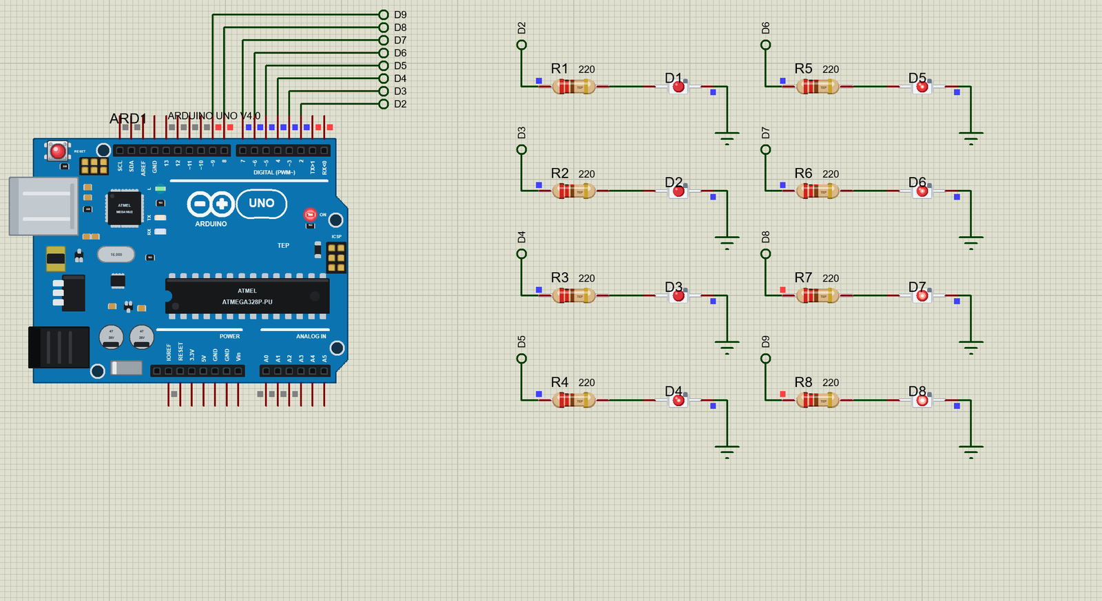
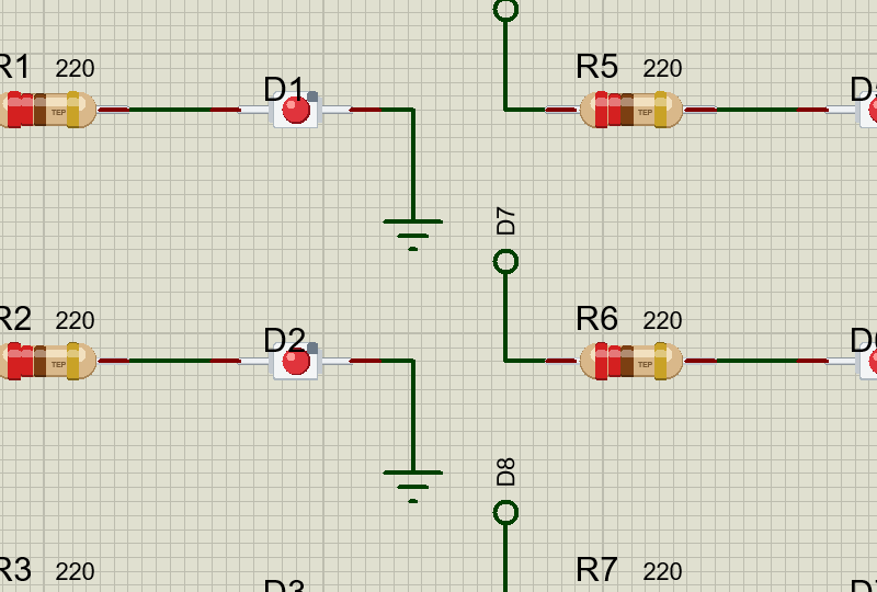
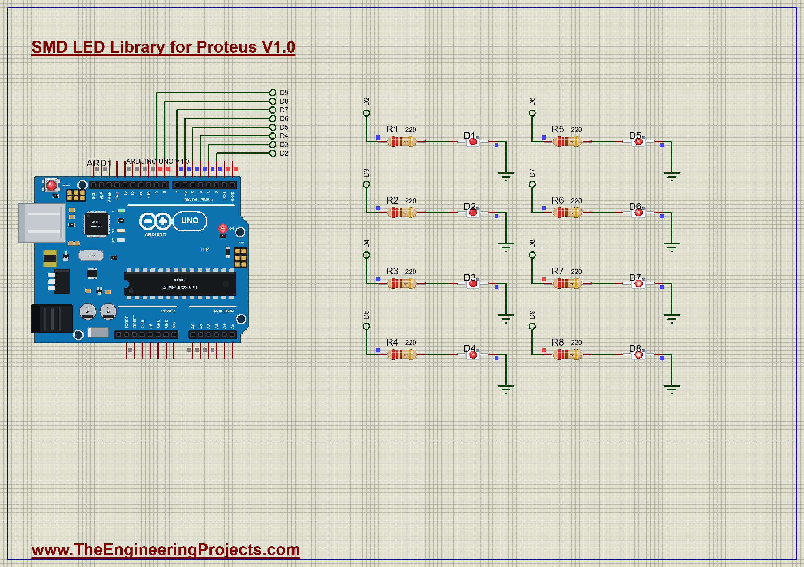
If you remember a certain talking car from the 1980s, you know this effect: a dot of light sweeping from side to side, with a glowing tail behind it. Eight red SMD LEDs, D1 to D8, sit on pins D2 to D9, each with its own 220 ohm resistor. Open SMD-LED-Scanner-ArduinoUnoV4.pdsprj. It runs on our Arduino UNO Library for Proteus V4.0, with its built-in monitor, the same window as our TEP Serial Monitor Advance for Proteus. The resistors are from our Resistor Library for Proteus, and our 5 mm LED Library for Proteus explains how to choose them.
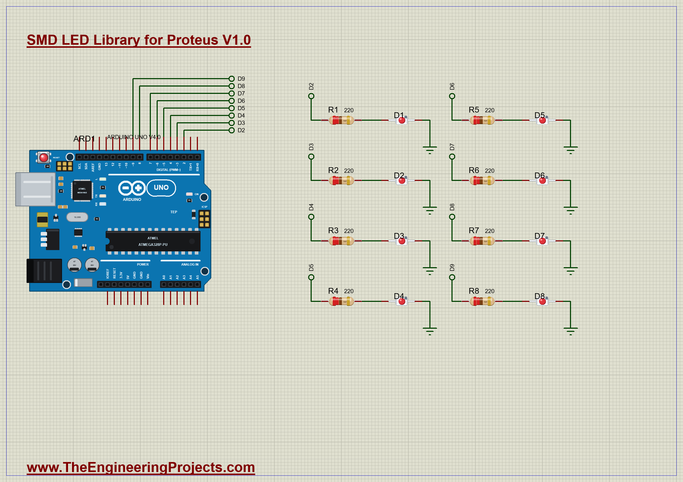
| Part | Connection | Job |
|---|---|---|
| D1 to D8 | K to GND | eight red 3528 LEDs |
| R1 to R8, 220 ohm | pins D2 to D9 to each A | one resistor for each LED |
Software PWM
A fading tail needs each LED to have its own brightness, and that means PWM. But an UNO has hardware PWM on only six pins, and only some of those are in our row. So the sketch makes its own, and this is called software PWM. It keeps a number from 0 to 16 for each LED. In a fast loop of 16 steps, each LED is on only for as long as the step is below its number. An LED at 16 is always on, and an LED at 4 is on for a quarter of the steps:
  for (byte step = 0; step < PWM_STEPS; step++) {
    for (byte k = 0; k < LEDS; k++) digitalWrite(FIRST_PIN + k, level[k] > step);
    delayMicroseconds(100);
  }
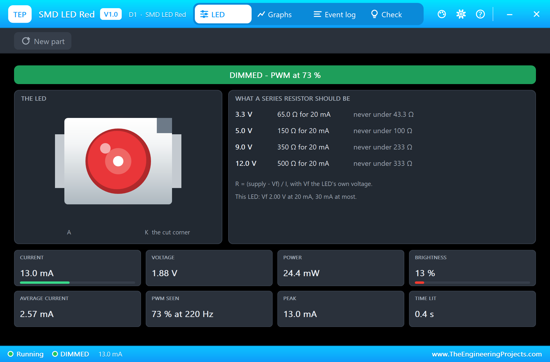
Each pass takes a little over 2 ms, so the LEDs flicker about 420 times a second, far too fast to see. You can read that very figure on the pop-up of any LED in the tail, in the PWM Seen tile.
The Fading Tail
The tail takes just one line. Each time the dot moves, every level is cut in half. So the LED the dot has just left drops from 16 to 8, then 4, then 2, and it fades away in a few steps. The dot itself is set back to full at the new place:
  for (byte k = 0; k < LEDS; k++) level[k] = level[k] / 2;     // the tail fades
  place += direction;
The Commands
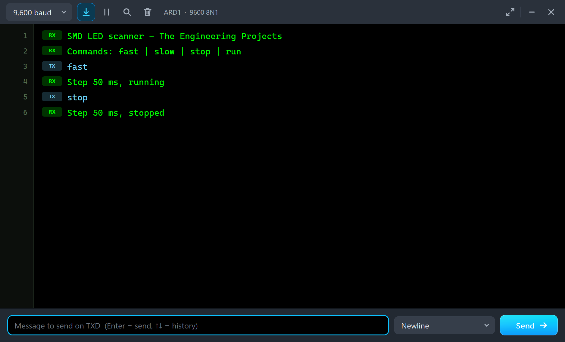
| Type this | What happens |
|---|---|
| fast | a step every 50 ms |
| slow | a step every 250 ms |
| stop | the dot stops where it is |
| run | it moves again |
Run the Demo
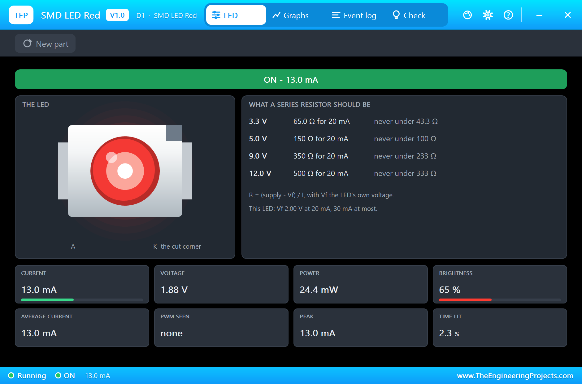
Press Run, and the dot starts to sweep. Click D1 to open its pop-up. The left card shows the chip, and the right card tells you what resistor to use for four common supplies:
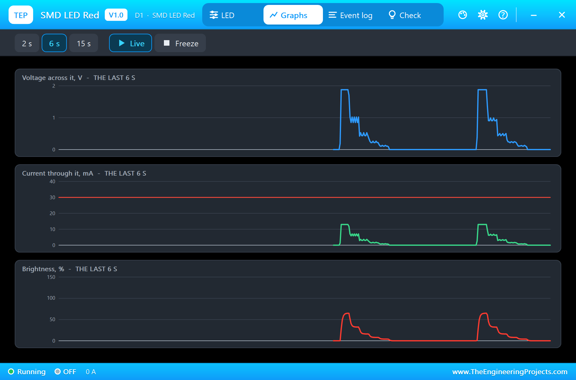
The Graphs tab shows the dot passing by: a tall pulse of current as it arrives, then a smaller and smaller set of pulses as the tail fades away:
Here is the complete circuit, truly running, with the dot and its tail on the sheet:
Stop the Dot
Type fast, and the dot rushes back and forth. Then type stop, and it freezes. Click the LED under the dot. It shows its real current, with the state ON, as the sketch has stopped moving:
The Log and the Check Page
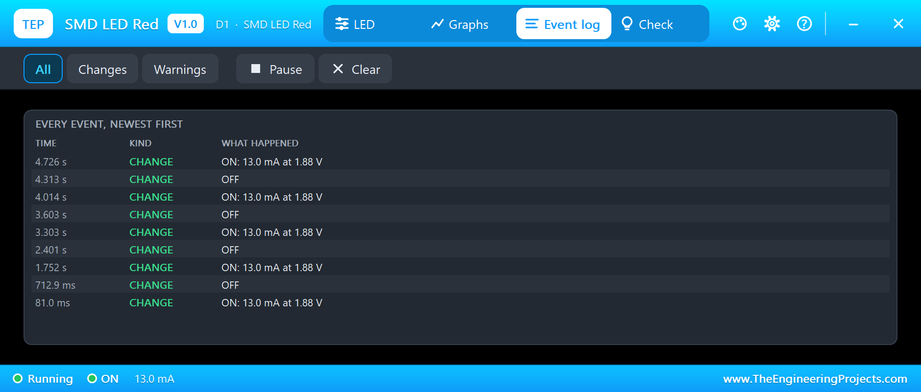
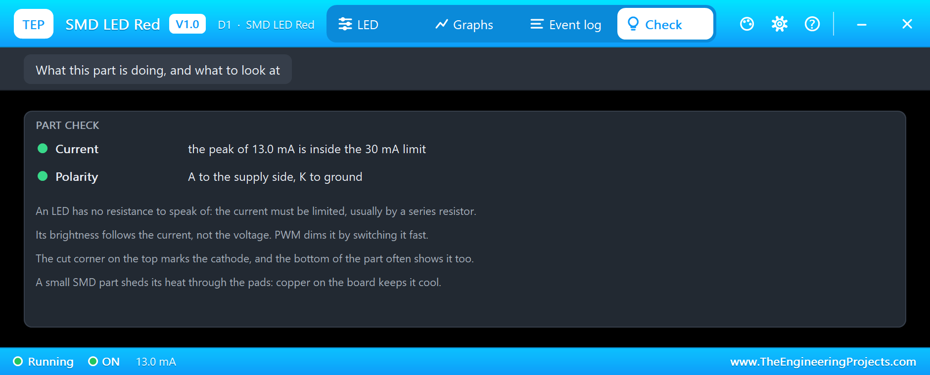
The Event log writes down each change, and the Check page looks at the current, the polarity and the PWM it can see:
Try It Yourself
- Change the fade from a half to a quarter, and see a shorter tail.
- Change
PWM_STEPSto 64, and see how the flicker rate falls. - Swap in green or amber parts for a different look.
- Remove the
delayMicroseconds, and watch the tail get brighter. - Change R1 to 100 ohm, and see that one LED stand out.
Ideas to Extend the Demo
- Make a bar graph that follows a sensor on A0.
- Set the speed with a potentiometer.
- Make two dots that bounce off each other.
- Drive more LEDs from fewer pins, with a 74HC595 shift register.
Your Own Sketches
The demo sketch is in the zip file, and you can change it in the Arduino IDE. New to Arduino? Start with our Arduino Tutorial for Beginners. Export the compiled binary, and set the UNO's PROGRAM property to the new file. Our guide on How to get the HEX file from Arduino shows you where the file ends up.
Things to Know Before Using a Real SMD LED
- Check the mark: the cathode mark differs between makers.
- Give it copper: heat leaves through the pads.
- Use one resistor per LED: LEDs in parallel do not share current fairly.
- Keep the iron short: too much heat cracks the resin and spoils the part.
- Watch the total current: an UNO allows about 200 mA across all its pins, so check it for long rows.
Troubleshooting
- It stays dark: A and K are swapped.
- BURNT OUT: use more ohms, then press New part.
- It is too small to see: it is at true scale. Zoom in on the sheet.
- The pop-up does not open: click the chip while the simulation runs.
- The part is not simulated:
TEPSMDLED.DLLis missing from MODELS and from the project folder.
Limitations of the Simulation
- The path of the heat through the pads is simplified to one figure.
- The viewing angle and the spectrum of the light are left out.
- The sheet repaints a few times a second, so a fast dot may look uneven.
- Arduino is a name of Arduino; this library is not made or endorsed by Arduino or Labcenter.
- Tested in Proteus 8.5 in October 2026 (the demo as shipped). Proteus 7 is not supported.
So, that was all about the SMD LED Library for Proteus. I hope you enjoy the little scanner, and that a tiny white square on a board will no longer feel like a mystery. If you have any questions, ask in the comments and I will help you out. Till the next tutorial, take care and have fun!

Comments
0