


Resistor Network Library for Proteus: SIP-9 and SIP-5 A103J


Hello friends, I hope you all are doing great. Today, I am going to share the new Resistor Network Library for Proteus. Many circuits need a row of identical resistors: eight LEDs, each with its own current limiting resistor, or eight data lines, each with a pull-up. You could place eight separate parts, or you could use one small black part with a row of pins along its bottom. That part is a resistor network, and it is one of the quiet heroes of tidy board design.
Resistor Network Library for Proteus
Latest version: V1.0 (November 2026, this tutorial)
Helping Tools
- Serial Monitor Advance: a serial terminal window for the UART of your board
- Serial Monitor Expert: the serial monitor with extra debugging tools
- LCD Library for Proteus V3.0: 16x2, 20x4 and I2C LCDs to show your readings
Our library has two bussed SIP networks at true scale: the SIP-9, with eight resistors, and the SIP-5, with four. Each has the black body, the dot that marks pin 1, and the print in the real format. Type a value and the print follows: 10k becomes A103J, and 330 ohm becomes A331J. The pop-up shows the current in every single resistor as a bar, and the total in the shared pin. The demo is an 8 LED level meter driven through one network, with a small 4 LED sweep counter on a second one.
NOTICE: Our team has put a lot of effort into these small parts: the bodies, the animation and the pop-ups are all our own design, and you get them free. Your feedback is the fuel that keeps us going, so please tell us what you think in the comments below or in the Resistor Network board of our forum. And if our free libraries help you, you can buy us a coffee. So, let's get started with the Resistor Network Library for Proteus:
What is a Resistor Network?
A resistor network, also called a resistor array or a resistor pack, is several resistors made together in one package. They are usually printed as thick film on a single ceramic strip, so they come from the same batch of material and sit at the same temperature. The package is often a SIP, a single in-line package, with all its pins in one row on the usual 2.54 mm pitch, so it drops straight into a breadboard or a strip of holes.
Inside, the resistors can be connected in different ways. In a bussed network, one end of every resistor is joined to a single shared pin, called the common. A 9 pin bussed network therefore holds eight resistors: pin 1 is the common, and pins 2 to 9 are the other ends. In an isolated network, each resistor has two pins of its own and nothing is shared. Our library models the bussed type, which is the one you will meet most often.
| Feature | The real part | In the library |
|---|---|---|
| SIP-9 | eight resistors, 22.9 mm long | 960 thou wide, true scale |
| SIP-5 | four resistors, 12.7 mm long | 534 thou wide, true scale |
| Pin 1 | the common, by the dot | the same |
| A103J and similar | the print follows the value | |
| Rating | about 0.2 W each | each resistor and the package checked |
Reading the Print
The print on a small SIP network is short but complete. The first letter tells you the circuit inside, and A is the bussed type with one common pin. The three digits are the value, in the same code we used in our SMD Resistor Library for Proteus: two digits and then the number of zeros, so 103 is 10k and 331 is 330 ohm. The last letter is the tolerance: J for 5 %, G for 2 % and F for 1 %.
| Circuit | Value | Tolerance | |
|---|---|---|---|
| A103J | bussed | 10k | 5 % |
| A331J | bussed | 330 ohm | 5 % |
| A472J | bussed | 4.7k | 5 % |
| A102G | bussed | 1k | 2 % |
Bigger networks from the large makers often carry a longer part number instead, which spells out the pin count, the circuit and the value in the same spirit. Whatever the format, always look for the dot or the bevel that marks pin 1. On a bussed network that is the common, and fitting the part backwards puts the common at the wrong end.
Why Use One?
The first reason is space and time. One SIP-9 takes the room of about two ordinary resistors lying flat, like the ones in our Resistor Library for Proteus, and it is placed in one go instead of eight. The second reason is matching. Because all the resistors are made together, their values are close to each other and they drift together with temperature. In a circuit where the ratio between resistors matters more than their exact value, that is worth a lot. The third reason is plain tidiness: a row of equal resistors becomes one part with one line in the parts list.
Where Are They Used?
The classic job is pull-up resistors. A bus of eight data lines, or a row of eight switches, each needs a resistor to a supply. A bussed network does it with the common on +5 V and the other pins on the lines. The second classic job is LED current limiting. Every LED in a row needs a resistor of its own, but those resistors can share one end, so a bussed network on the cathodes, with its common to ground, does the work of eight resistors. That is exactly how our demo uses one. Networks also appear as bus terminators on long data lines, and special ones with two values, in a ladder pattern, are the heart of simple digital to analog converters.
One Resistor Each, Not One for All
A common mistake is to drive several LEDs in parallel through a single resistor. It seems to save parts, but LEDs are not all equal: the one with the lowest forward voltage hogs the current, and the brightness varies. A network gives every LED its own resistor, so the currents stay even, while still being only one part on the board. In our run the green, yellow and red LEDs each drew their own current, set by their own resistor.
The Common Pin and the Ratings
A bussed network has two limits to respect. Each resistor has its own power rating, usually about 0.2 W. The package as a whole also has a rating, about 1 W for a SIP-9, because all the heat leaves through the same small body. And remember the common pin: it carries the sum of all the currents. With eight LEDs at 9 mA each, the common pin carries over 70 mA. That is no problem here, but with eight loads of 50 mA each it would be 400 mA through one pin, and that is worth checking.
Choosing the Value
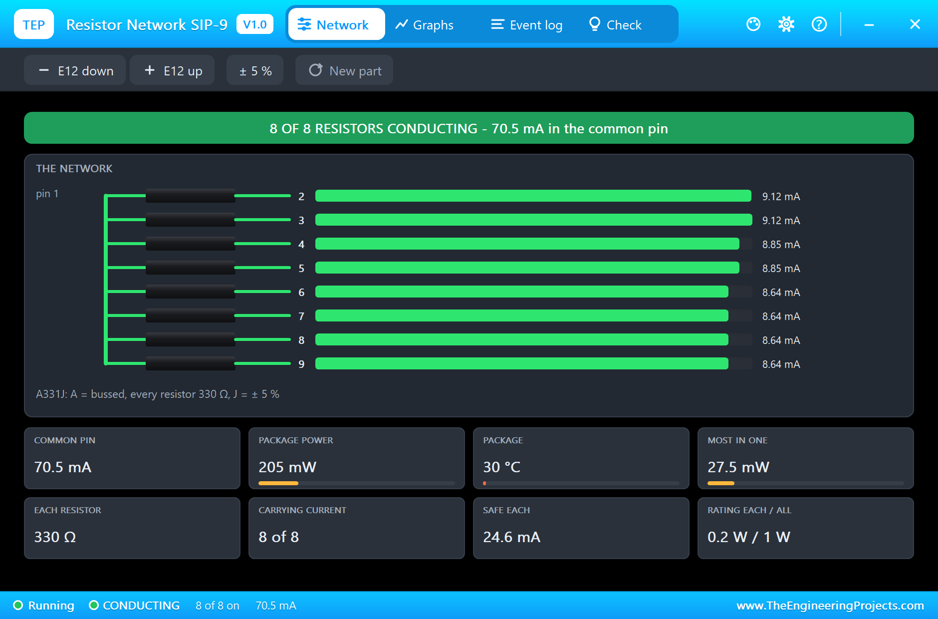
For LEDs, the value comes from a simple sum. Take the supply, subtract the forward voltage of the LED, and divide by the current you want. On a 5 V Arduino pin, with an LED that drops about 2 V, a 330 ohm resistor gives (5 - 2) / 330, or about 9 mA. That is bright enough for an indicator and kind to the pin. Our run agreed: every resistor of RN1 carried between 8.64 and 9.12 mA.
For pull-ups, the value is a balance. A low value, such as 1k, pulls hard and resists noise, but wastes current whenever a switch closes. A high value, such as 47k, wastes almost nothing, but leaves the line slow and easy to disturb. Most designs settle on 4.7k or 10k, which is why A472J and A103J are the networks you will find in almost every parts drawer.
Features of the Resistor Network Library for Proteus
- The real look, at true scale: the black body, the pin 1 dot, the leads on 2.54 mm and our small TEP signature.
- Two sizes: the SIP-9 with eight resistors and the SIP-5 with four.
- The print follows the value: the circuit letter, the value code and the tolerance letter.
- Every resistor on show: the pop-up draws the bussed network with each resistor's current as a bar.
- Both ratings checked: each resistor's power and the whole package's power and temperature.
- The common pin's total: the current in the shared pin, live.
- A pop-up for every part: click the network at Run for the network view, eight live values, graphs, an event log and a check page.
- A complete package: about 1.5 MB with the library, our Arduino UNO V4.0, the demo's LEDs and the demo, without the source code of the models.
The Resistor Networks in Proteus
The devices are RESNETSIP9TEP and RESNETSIP5TEP in TEPRESNET.LIB, under Resistors, Resistor Networks, with the prefix RN and the model TEPRESNET.DLL. Search RESNET in Pick Devices. Pin 1, by the dot, is the common; the other pins follow in order.
The Properties
| Property | What it does |
|---|---|
| Resistance (VALUE) | every resistor in the network; type 10k, 330 or 4k7, and the print follows |
| Tolerance, % | 5 prints J, 2 prints G, 1 prints F |
| Power per resistor, W | 0.2 by default |
| Print while stopped | the print the sheet shows while stopped; the run sets it to match |
Download Resistor Network Library for Proteus
Click the button below to download Resistor-Network-Library-for-Proteus-v1.0.zip (about 1.5 MB, without the source code of the models):
Resistor Network Library for Proteus V1.0- README.txt: installation, the demo, the properties, troubleshooting and the limits.
- Proteus Library Files:
TEPRESNET.LIB,TEPLED5MM.LIBand ourArduinoV4TEP.LIB. - Proteus Model Files:
TEPRESNET.DLL,TEPLED5MM.DLLandTEPARDUINO.DLL. - Arduino Code: the demo sketch.
- Proteus Simulation: the demo project, its HEX file and copies of the DLLs.
No Proteus yet? Read How to Download and Install Proteus 7 and 8. New to libraries? Follow How to Install a New Library in Proteus.
How to Install Resistor Network Library for Proteus
- Close Proteus and extract the whole zip file, for example to your Desktop.
- Copy the files from Proteus Library Files into the LIBRARY folder of Proteus.
- Copy the files from Proteus Model Files into the MODELS folder.
- Delete
TEPRESNET.IDXfrom the LIBRARY folder if it is there. - Start Proteus, press P and search for RESNET.
Demo: A Level Meter with One Network
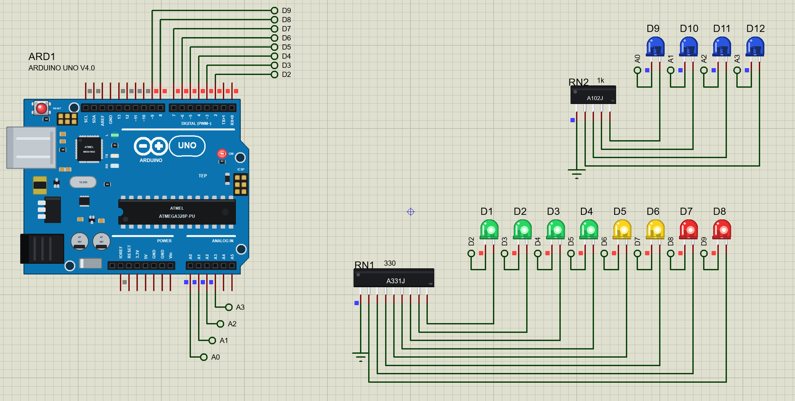
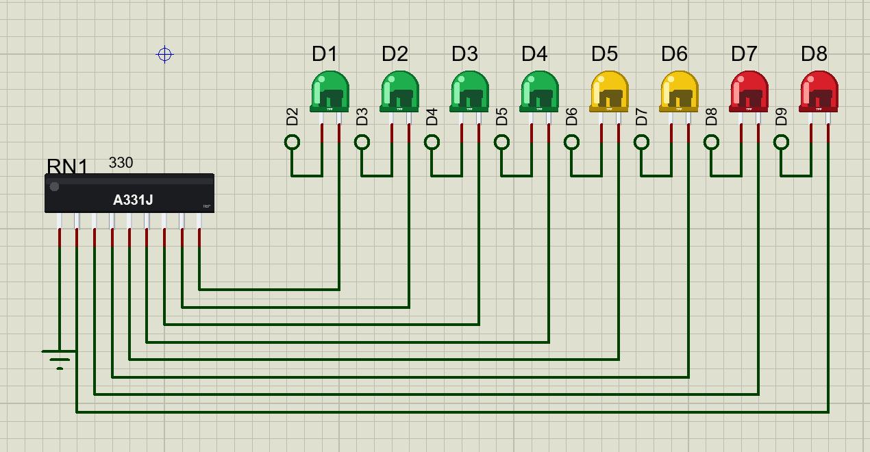
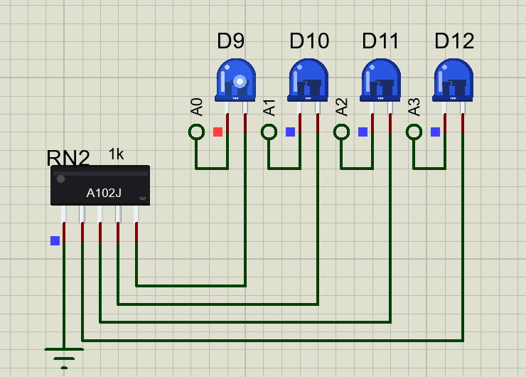
Eight LEDs, four green, two yellow and two red, form a level meter on pins D2 to D9. Their cathodes go to RN1, a SIP-9 printed A331J, and its common pin goes to ground. Each LED therefore has its own 330 ohm resistor, all in one part. Above them, four blue LEDs on A0 to A3 count the sweeps of the meter in binary, through RN2, a SIP-5 printed A102J. Open Resistor-Network-Level-Meter-ArduinoUnoV4.pdsprj. It runs on our Arduino UNO Library for Proteus V4.0, with its built-in monitor, the same window as our TEP Serial Monitor Advance for Proteus. The LEDs are from our 5 mm LED Library for Proteus.
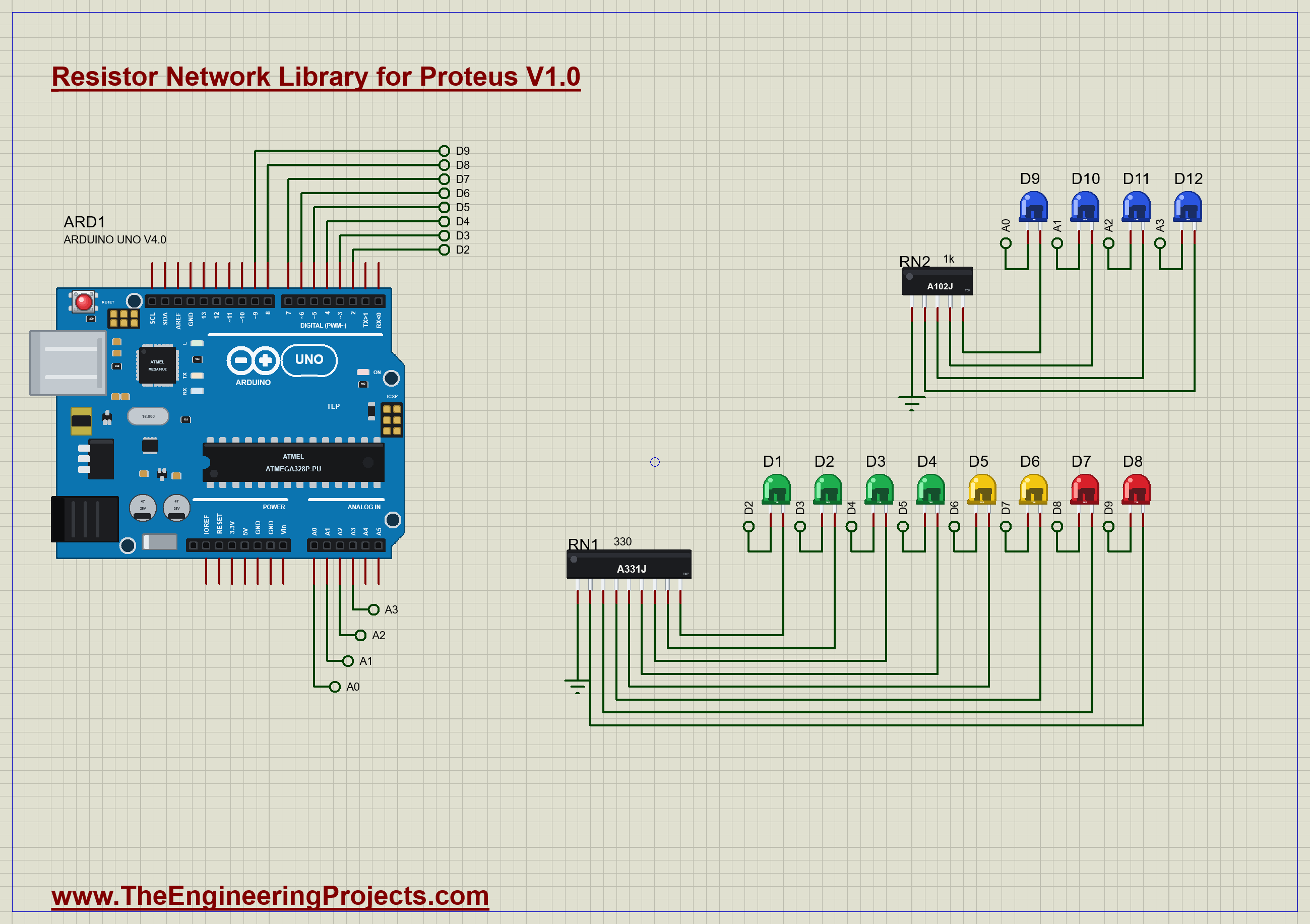
| Part | Connection | Job |
|---|---|---|
| D1 .. D8 | anodes on D2 .. D9 | the level meter |
| RN1 (SIP-9, A331J) | pins 9 .. 2 to the cathodes, pin 1 to GND | eight 330 ohm resistors |
| D9 .. D12 | anodes on A0 .. A3 | the sweep counter |
| RN2 (SIP-5, A102J) | pins 5 .. 2 to the cathodes, pin 1 to GND | four 1k resistors |
Notice that LED D1 uses pin 9 and LED D8 uses pin 2. In a bussed network every resistor is the same, so any LED may use any pin. Wiring them in reverse order lets the eight wires nest neatly without crossing each other on the sheet.
The Sketch
The meter itself is one short function. For a given level it turns on the first LEDs and turns off the rest:
void showLevel(byte level) {
  for (byte k = 0; k < LEDS; k++) digitalWrite(FIRST_PIN + k, k < level ? HIGH : LOW);
}
The loop raises the level one LED at a time, holds the full bar for two seconds, and lowers it again. After every sweep it counts, and shows the count on the four blue LEDs in binary:
  sweeps = (sweeps + 1) & 0x0F;
  showCount(sweeps);
Run the Demo
Press Run. The meter climbs, one LED at a time, and stops for two seconds with all eight lit. Here is the complete circuit, truly running at the top of the sweep:
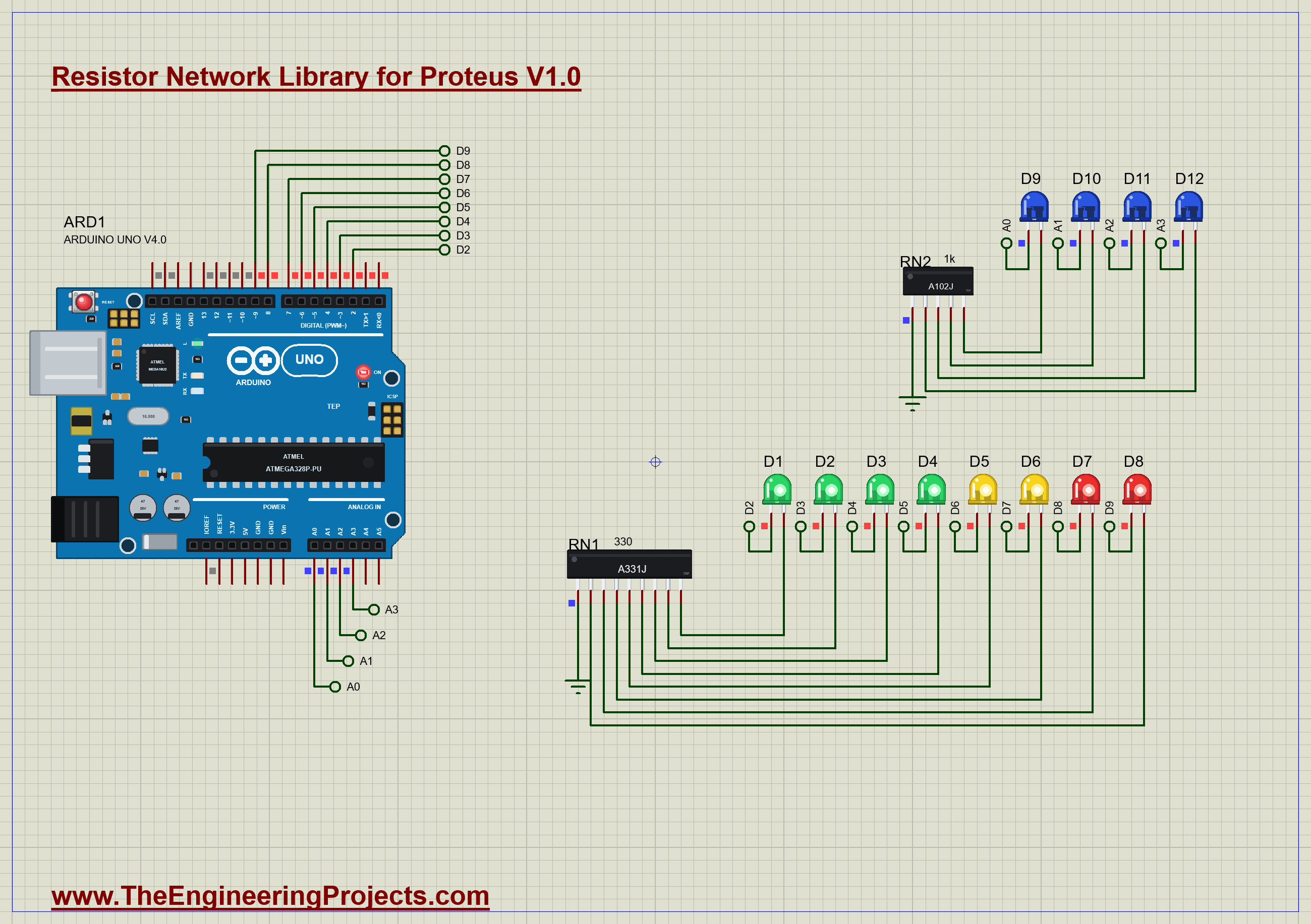
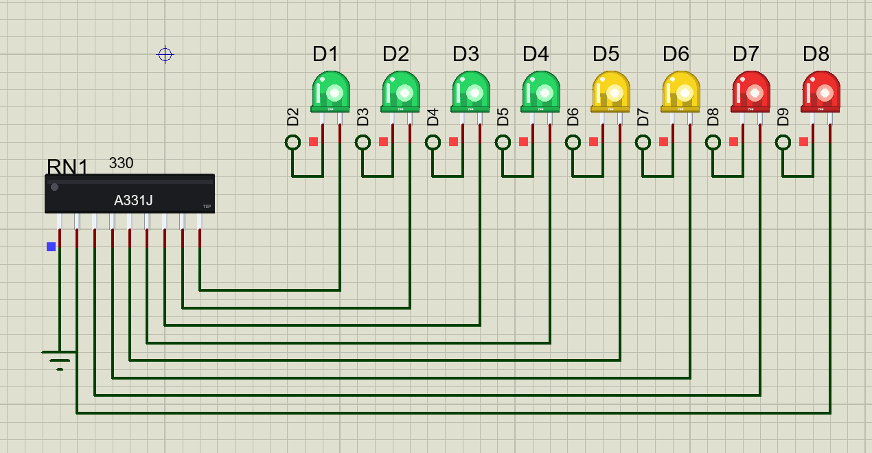
Click RN1 to open its pop-up. Every resistor carries current, between 8.64 and 9.12 mA: the red LEDs have the lowest forward voltage, so they draw the most. The common pin carries the sum, 70.5 mA, and the package burns 205 mW, a fifth of its 1 W:
Half Way Down
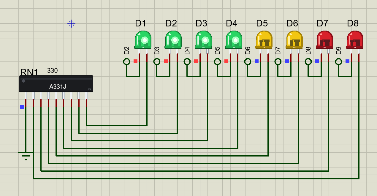
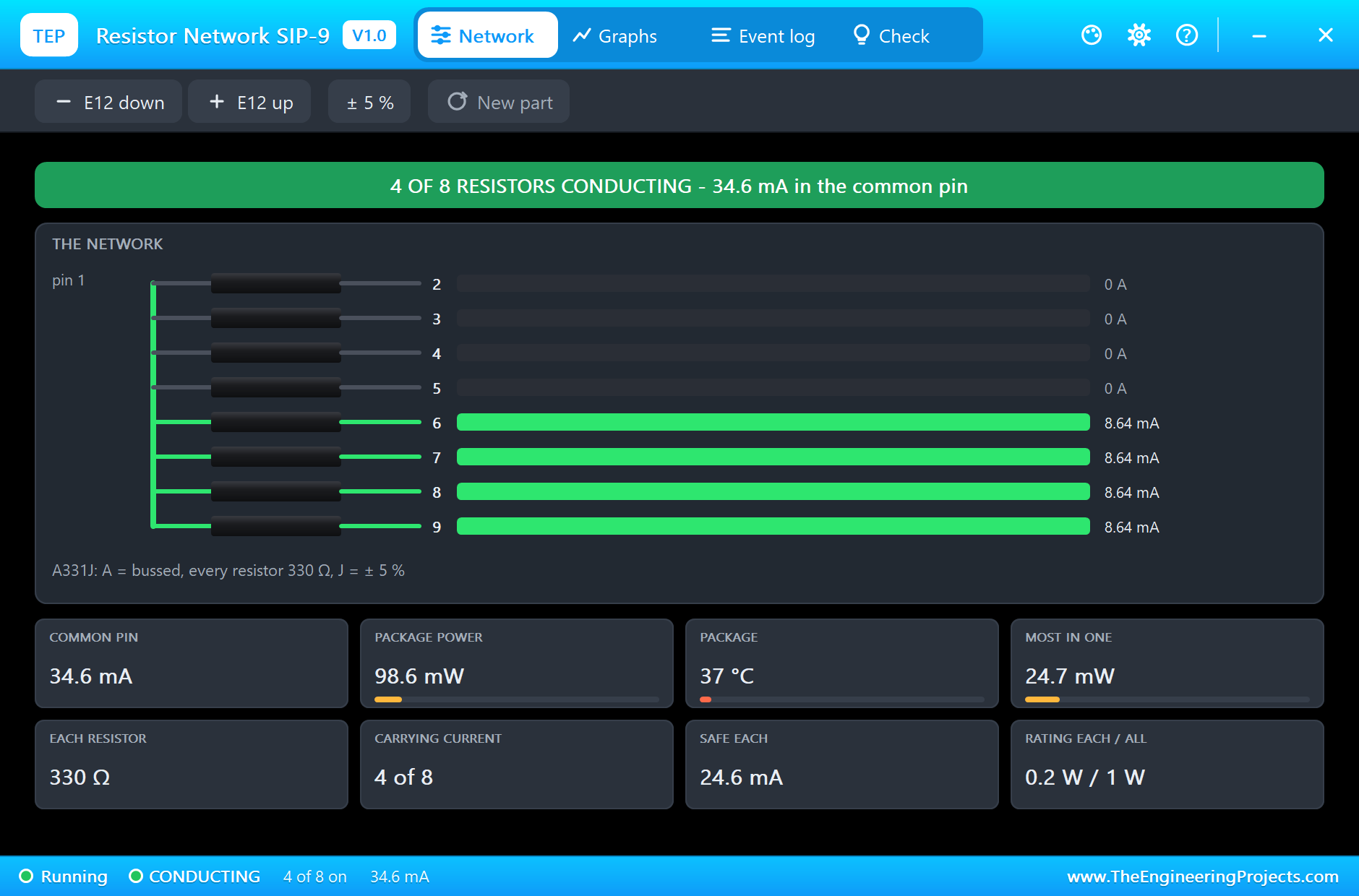
As the level falls, the pop-up follows it. With four LEDs left, only four resistors carry current, 8.64 mA each, and the common pin falls to 34.6 mA:
The Sweep Counter
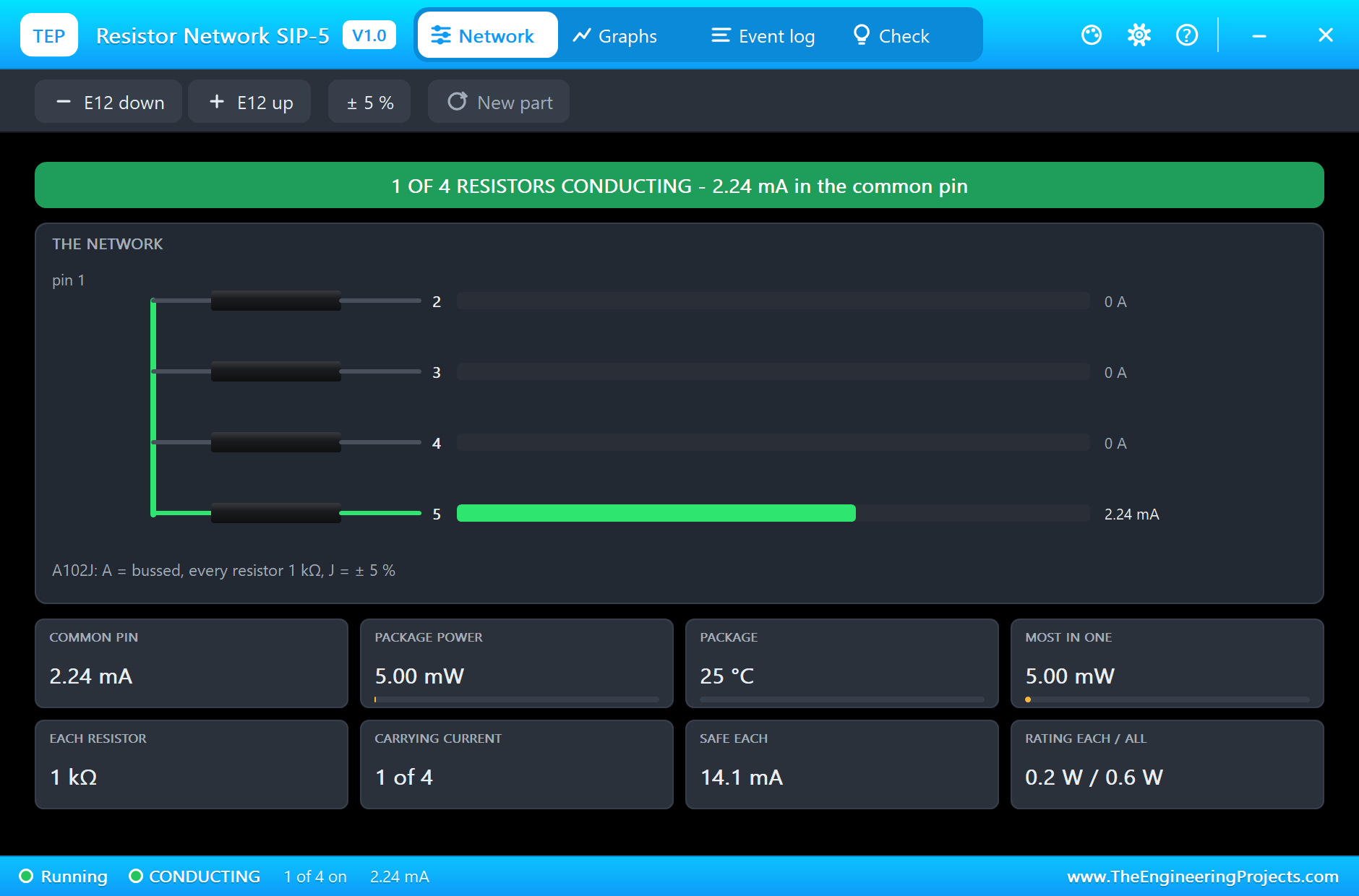
After the first sweep, the count is 1, so the first blue LED lights. It runs through one of RN2's 1k resistors, at 2.24 mA, and RN2's pop-up shows one resistor of four at work:
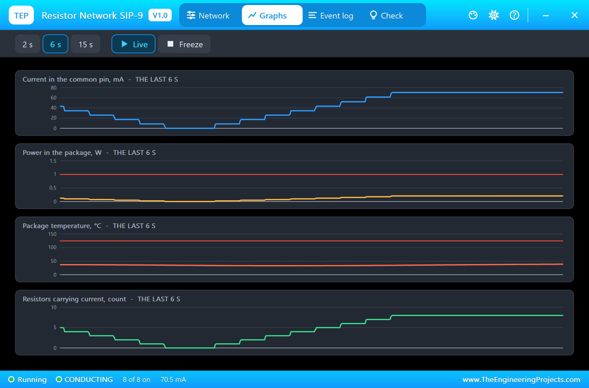
The Graphs tab of RN1 shows the meter beautifully: the current in the common pin rises and falls in eight even steps, and the count of resistors carrying current follows the same staircase:
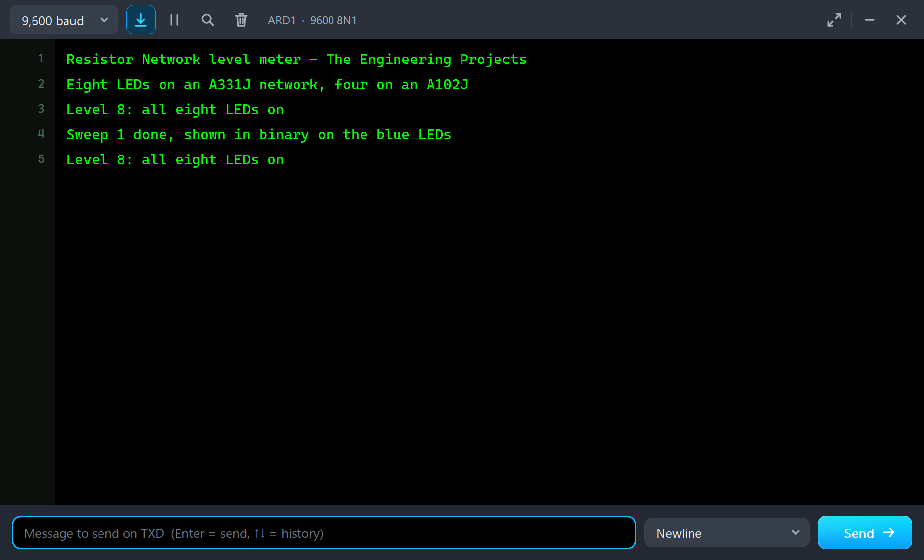
The monitor marks each full bar and each finished sweep:
The Log and the Check Page
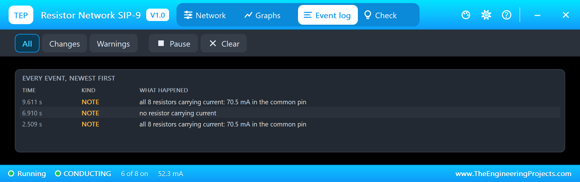
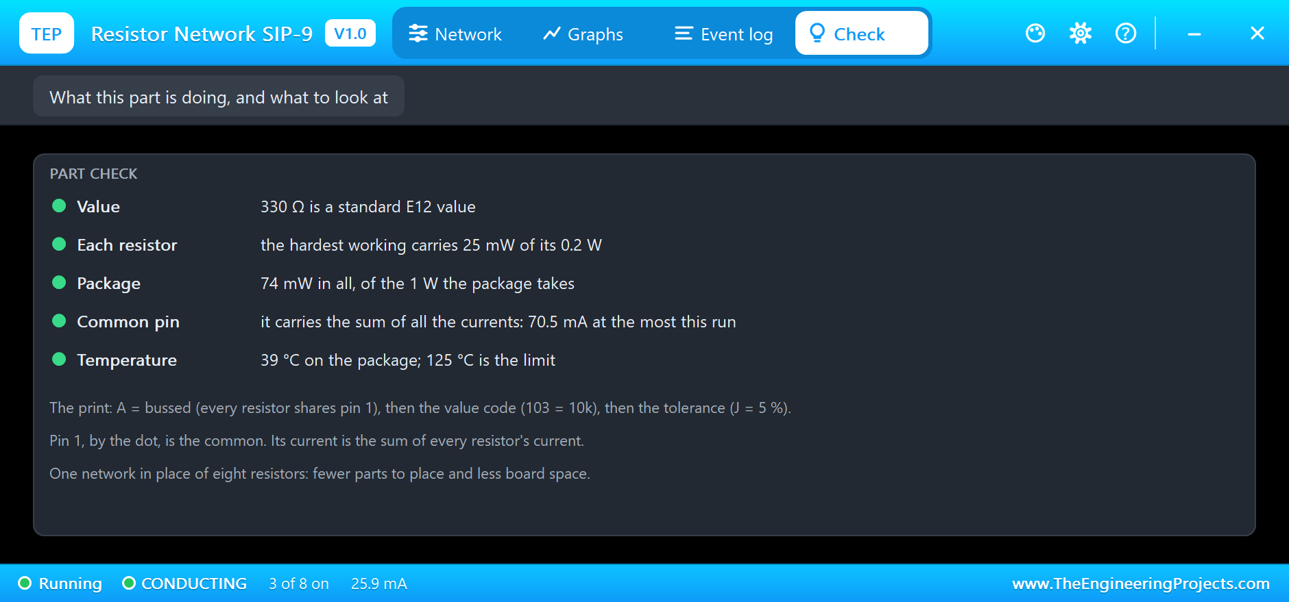
The Event log notes each moment when all eight resistors work, with the 70.5 mA in the common pin, and each moment when none does. The Check page judges the hardest working resistor against its own rating, the package against its rating, and reports the most the common pin has carried:
Try It Yourself
- Use E12 down on RN1 to lower the resistors to 220 ohm, and watch the common pin's current climb.
- Keep going down, and find where a single resistor passes its 0.2 W.
- Swap two LED wires on the network, and confirm that nothing changes: every resistor is the same.
- Turn RN2 into four pull-ups: common to +5V, the other pins to four inputs.
- Change the meter to show a reading from a potentiometer on another analog pin.
Ideas to Extend the Demo
- Make a 16 LED meter with two SIP-9 networks.
- Use a network as pull-ups for an 8 way DIP switch, and read it as a byte.
- Drive a 7-segment display with a network on its eight segments.
- Build a sound level meter with a microphone module and the eight LEDs.
Your Own Sketches
The demo sketch is in the zip file, and you can change it in the Arduino IDE. New to Arduino? Start with our Arduino Tutorial for Beginners. Export the compiled binary, and set the UNO's PROGRAM property to the new file. Our guide on How to get the HEX file from Arduino shows you where the file ends up.
Things to Know Before Using a Real Resistor Network
- Find pin 1: on a bussed network it is the common, marked by a dot or a bevel.
- Check both ratings: each resistor's power and the whole package's power.
- Mind the common pin: it carries the sum of all the currents.
- Bussed or isolated: read the circuit letter or the datasheet before you design around one.
- Leave some lead length: a SIP stands upright, and a short lead makes it easy to bend.
Troubleshooting
- An LED stays dark: check that its cathode reaches a network pin, and that pin 1 reaches GND.
- Every resistor reads 0 A: pin 1, the common, is not connected.
- The LEDs light unevenly: that is normal for different colours, which have different forward voltages.
- The stopped print differs from the value: the Check page says which Print while stopped to pick, and a run sets it for you.
- The part is not simulated:
TEPRESNET.DLLis missing from MODELS and from the project folder.
Limitations of the Simulation
- Only the bussed type is modelled; isolated networks are not included.
- All the resistors have exactly the same value: tolerance spread and matching are left out.
- The package's heat is shared evenly; a real one is hotter where the busiest resistor sits.
- Arduino is a name of Arduino; this library is not made or endorsed by Arduino or Labcenter.
- Tested in Proteus 8.5 in November 2026 (the demo as shipped). Proteus 7 is not supported.
So, that was all about the Resistor Network Library for Proteus. I hope you enjoy replacing a whole row of resistors with one neat part, and that you always remember to find pin 1 and to count the current in the common pin. If you have any questions, ask in the comments and I will help you out. Till the next tutorial, take care and have fun!

Comments
0