


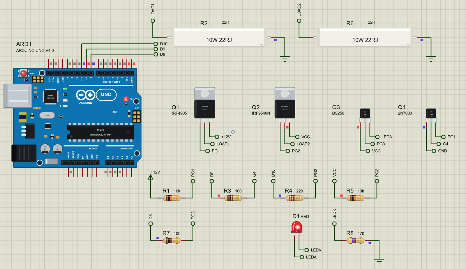
P-MOSFET Library for Proteus: IRF9540N, IRF4905 and BS250


Hello friends, I hope you all are doing great. Today, I am going to share the new P-MOSFET Library for Proteus. The P-channel MOSFET is the switch of the high side: its source sits on the supply, the load hangs from its drain down to ground, and it connects or cuts the power to a whole circuit. It is how a battery-powered gadget switches its sensors off to save power, how a board protects itself against a reversed battery, and how a microcontroller turns on a 12 V load that must keep its ground connected.
P-MOSFET Library for Proteus
Latest version: V1.0 (November 2026, this tutorial)
Helping Tools
- Serial Monitor Advance: a serial terminal window for the UART of your board
- Serial Monitor Expert: the serial monitor with extra debugging tools
- LCD Library for Proteus V3.0: 16x2, 20x4 and I2C LCDs to show your readings
Our library has three of the most used P-channel MOSFETs at true scale: the IRF9540N, a 100 V power MOSFET in TO-220; the IRF4905, one of the strongest P-channel parts in a TO-220 package, with only 20 mΩ when fully on; and the small BS250 in TO-92. The model has the real channel with its threshold and its two regions, the gate capacitance, the body diode and the junction temperature on a heatsink, and every value keeps its real sign: a P-MOSFET is on with its gate below its source, so its gate voltage is negative. The demo switches three loads on the high side, one of them on 12 V through a level shifter, and shows the two ways to drive a P-MOSFET from an Arduino.
NOTICE: Our team has put a lot of effort into these small parts: the bodies, the animation and the pop-ups are all our own design, and you get them free. Your feedback is the fuel that keeps us going, so please tell us what you think in the comments below or in the P-MOSFET board of our forum. And if our free libraries help you, you can buy us a coffee. So, let's get started with the P-MOSFET Library for Proteus:
What is a P-Channel MOSFET?
A MOSFET, a metal-oxide-semiconductor field-effect transistor, has three pins: the gate, the drain and the source. The gate sits on a thin layer of oxide above the silicon and is insulated from everything else. In a P-channel MOSFET the silicon under the gate is N-type, and a gate voltage below the source draws positive carriers, holes, into a thin channel under the oxide. The channel lets current flow from the source to the drain. The further the gate is pulled below the source, the wider the channel and the lower the resistance. With the gate at the source voltage there is no channel, and the MOSFET is an open switch.
It is the mirror image of the N-channel MOSFET in our N-MOSFET Library for Proteus. Every voltage is turned around: the gate-source voltage Vgs is negative when it is on, the drain-source voltage Vds is negative, and the current flows in at the source and out at the drain. Datasheets write the ratings with minus signs, such as -55 V and -74 A, and our pop-up keeps those signs, so the numbers you read in Proteus are the numbers you will find in the datasheet.
| Part | Package, pins | Ratings | On resistance | Gate capacitance |
|---|---|---|---|---|
| IRF9540N | TO-220, G D S | -100 V, -23 A | 117 mohm at Vgs -10 V | 1.3 nF |
| IRF4905 | TO-220, G D S | -55 V, -74 A | 20 mohm at Vgs -10 V | 3.4 nF |
| BS250 | TO-92, S G D | -45 V, -230 mA | about 14 ohm at Vgs -10 V | 60 pF |
Why Switch the High Side?
An N-channel MOSFET is easiest to use on the low side, between the load and ground: its source is on ground, and a pin's 5 V is a positive gate voltage. But then the load is not connected to ground when it is off; both of its wires sit at the supply voltage. That does not matter for a lamp or a motor, but it does matter for a sensor module, a radio or anything that talks to the microcontroller over a data line, because its ground must stay connected to the rest of the circuit. A switch on the high side cuts the supply instead and leaves the ground alone.
An N-channel MOSFET can switch the high side too, but its gate must then rise above the supply, which needs a charge pump or a bootstrap driver. A P-channel MOSFET does it with nothing more than a resistor: its source sits on the supply, and pulling the gate down to ground turns it on. That simplicity is why P-MOSFETs appear on almost every battery-powered board, as load switches, as power-path switches between a USB supply and a battery, and as reverse polarity protection.
The Gate Below the Source
The threshold voltage, Vth, of a P-channel MOSFET is negative: about -2 to -4 V. At the threshold the channel just begins to form and only a trickle of current flows. The datasheet rates the on resistance at a stated gate voltage, usually -10 V for a standard part and -4.5 V for a logic-level one. Our three parts are rated at -10 V: the IRF9540N and the IRF4905 have a threshold of about -3 V in our model, the BS250 about -2 V. What matters is never the gate voltage measured to ground, but the gate voltage measured to the source. With the source on 12 V, a gate at 0 V is -12 V and fully on; a gate at 12 V is 0 V and off; and a gate at 5 V is still -7 V, which is on.
Driving a P-MOSFET From a Microcontroller
That last case is the classic mistake. When the supply of the load is the same 5 V as the microcontroller, the pin can drive the gate directly: LOW turns it on and HIGH turns it off, the reverse of an N-channel switch. But when the load runs on 12 V, a pin that goes HIGH reaches only 5 V, the gate is still 7 V below the source, and the MOSFET never turns off. Worse, the pin is now connected to a gate that is pulled towards 12 V by the pull-up resistor, and the current flows into the pin's protection diodes.
The answer is a level shifter: a small NPN transistor or a small N-channel MOSFET such as the 2N7000 pulls the gate down to ground, and a pull-up resistor of about 10k from the gate to the source turns it off when the small transistor lets go. The pin only ever sees the gate of the 2N7000. Note that the logic is now the right way round again: the pin HIGH turns the 2N7000 on, which pulls the gate down and turns the P-MOSFET on. On a supply above 20 V a zener diode or a resistor divider must also keep the gate within its rating, usually -20 V.
P-Channel Against N-Channel
Holes move through silicon about two to three times more slowly than electrons, so a P-channel MOSFET has a higher resistance than an N-channel part of the same size. The IRF9540N has 117 mΩ, while its N-channel twin in the same package, the IRF540N, has 44 mΩ. To reach a low resistance a P-channel MOSFET needs a bigger die and therefore more gate capacitance: the IRF4905 reaches 20 mΩ, but its gate is a 3.4 nF capacitor. For the highest currents engineers use N-channel parts with gate drivers; for most load switches up to a few amps a P-channel part is the simpler answer.
The Gate Capacitance
The gate and the channel form a capacitor, Ciss in the datasheet. Every time the gate switches, that capacitor is charged or discharged, and the current that does it is short but large. In a level shifter the small N-MOSFET discharges the gate very quickly, but the pull-up resistor charges it back up slowly: 10k and 3.4 nF have a time constant of 34 µs. At the 490 Hz of analogWrite that hardly matters, but at 20 kHz it would, and fast PWM on the high side needs a smaller pull-up or a push-pull gate driver. Our model charges the gate through whatever drives it, and the pop-up shows the peak gate current.
The Body Diode
Every power MOSFET has a diode built in. In a P-channel part it runs from the drain to the source: it conducts if the drain is pulled above the source. In reverse polarity protection this diode is the trick: with the battery the right way round, the body diode conducts first, the gate sees a negative voltage and the channel turns on and bypasses it. With the battery reversed, the diode blocks and the gate stays off. The body diode is not a flyback diode for a coil on the drain, which still needs its own diode. Our model includes it, and the pop-up says when it conducts.
Power and the Heatsink
A MOSFET that is fully on dissipates I squared times Rds(on). Half an amp through the 17 mΩ of an IRF4905 is only about 5 mW. At 10 A it would be 2 W, enough to need a heatsink. Our TO-220 parts take a HEATSINK property, NONE, SMALL or LARGE, and the junction temperature follows the power, with a warning at 150 °C and a failure past the part's limit. The BS250 in its tiny TO-92 package is meant for small loads up to 230 mA.
Where They Are Used
P-channel MOSFETs switch the power of sensors, displays and radios in battery-powered devices, choose between a USB supply and a battery, protect boards against reversed batteries, switch 12 V loads that must keep their ground, and form the upper half of H-bridges together with N-channel parts. The BS250 is a small high-side switch for LEDs, buzzers and other small loads.
Features of the P-MOSFET Library for Proteus
- The real look, at true scale: two TO-220 power MOSFETs with their tabs and a TO-92 BS250, and our small TEP signature.
- A real channel with real signs: a smooth threshold below the source, the ohmic and saturation regions, channel-length modulation and the drain resistance, with Vgs, Vds and the threshold shown as negative numbers.
- The datasheet resistance: each part reaches its rated Rds(on) at -10 V, and warns when its gate is not pulled far enough below its source.
- The gate capacitance: charged through whatever drives it, a pin, a resistor or a level shifter, with its peak current on the pop-up.
- The body diode and the junction temperature: through the heatsink you choose, with a failure past its limit.
- PWM recognised: its frequency and duty read from the gate, one line in the log, not three an edge.
- A pop-up for each part: the region, Rds now, the gate drive below the source against its rating, the output curves, graphs, an event log and a check page.
- A complete package: about 2.5 MB with the library, our Arduino UNO V4.0, our 2N7000, power resistors, resistors and LED and the demo, without the source code of the model.
The P-MOSFETs in Proteus
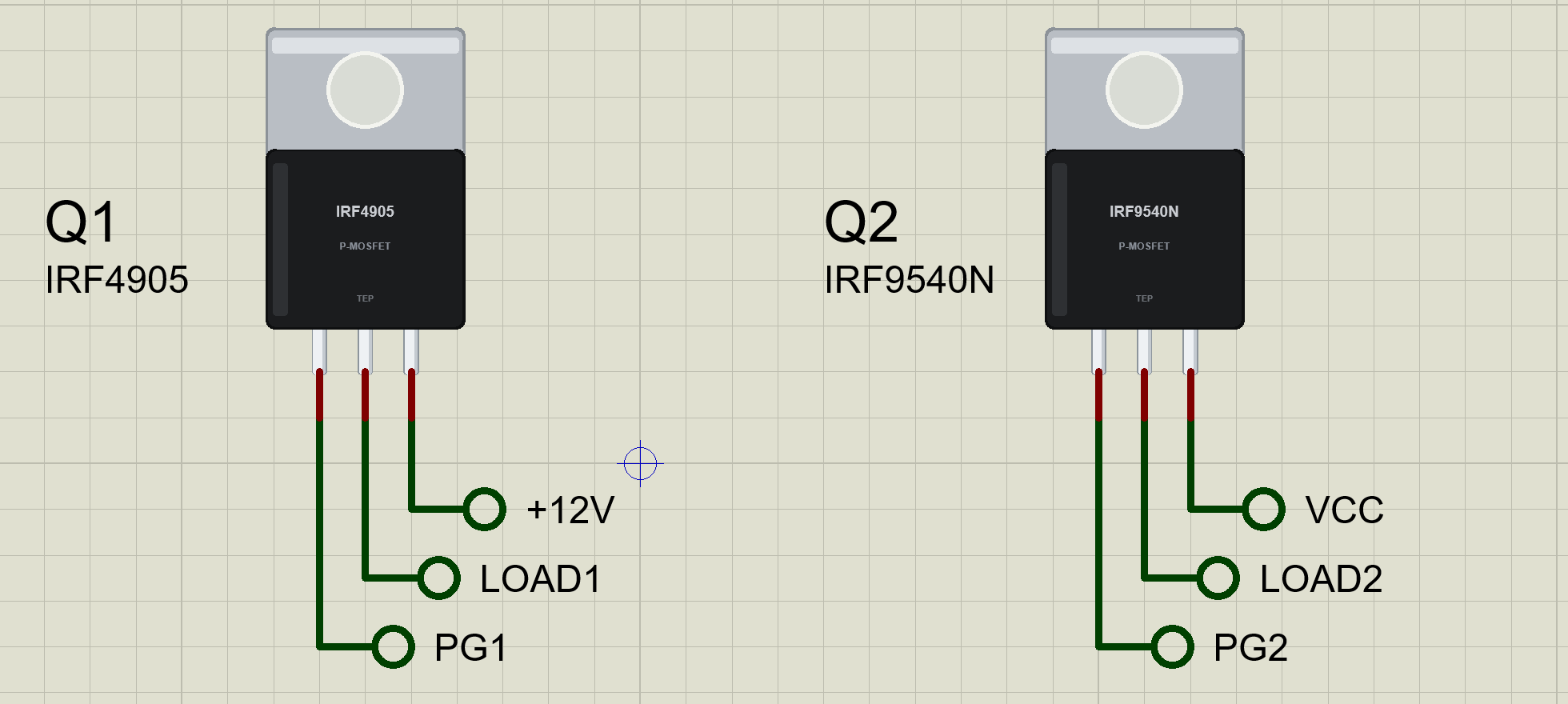
The devices are IRF9540NTEP, IRF4905TEP and BS250TEP in TEPPMOS.LIB, under Transistors, MOSFET, with the prefix Q and the model TEPPMOS.DLL. Search IRF9540, IRF4905 or BS250 in Pick Devices. The TO-220 parts are G D S from the left, with the tab on the drain; the BS250 is S G D with its flat face towards you.
The Properties
| Property | What it does |
|---|---|
| Part (VALUE) | IRF9540N, IRF4905 or BS250 |
| Heatsink (TO-220 only) | NONE (2.0 W safe), SMALL (7.6 W), LARGE (19 W) |
Download P-MOSFET Library for Proteus
Click the button below to download P-MOSFET-Library-for-Proteus-v1.0.zip (about 2.5 MB, without the source code of the models):
P-MOSFET Library for Proteus V1.0- README.txt: installation, the demo, the wiring of a high-side switch, the heatsink settings, troubleshooting and the limits.
- Proteus Library Files:
TEPPMOS.LIB, our N-MOSFET, resistor, power resistor and LED libraries, and ourArduinoV4TEP.LIB. - Proteus Model Files:
TEPPMOS.DLL, the DLLs of those parts andTEPARDUINO.DLL. - Arduino Code: the demo sketch.
- Proteus Simulation: the demo project, its HEX file and copies of the DLLs.
No Proteus yet? Read How to Download and Install Proteus 7 and 8. New to libraries? Follow How to Install a New Library in Proteus.
How to Install P-MOSFET Library for Proteus
- Close Proteus and extract the whole zip file, for example to your Desktop.
- Copy the files from Proteus Library Files into the LIBRARY folder of Proteus.
- Copy the files from Proteus Model Files into the MODELS folder.
- Delete
TEPPMOS.IDXfrom the LIBRARY folder if it is there. - Start Proteus, press P and search for IRF4905.
Demo: Three High-Side Switches
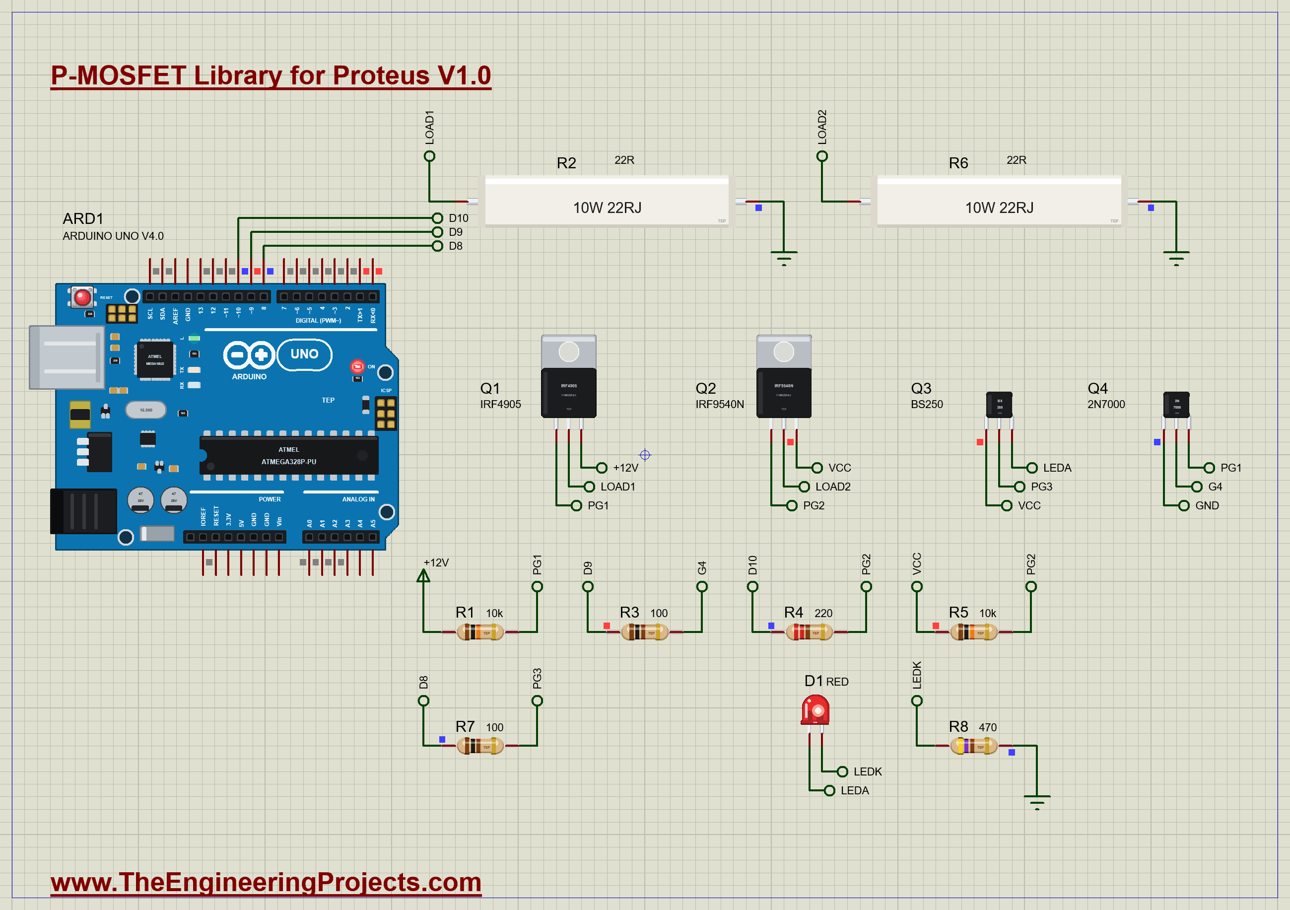
Each P-MOSFET has its source on a supply and its load from its drain to ground. Q1, the IRF4905, switches a 12 V load, one of our 10 W power resistors at 22 Ω, about half an amp. A pin cannot drive it directly, so Q4, a 2N7000 from our N-MOSFET Library for Proteus, pulls its gate down from D9 through a 100 Ω gate resistor R3, and R1, 10k, pulls the gate back up to +12V. Q2, the IRF9540N, switches an identical load on the 5 V supply, with its gate straight from D10 through 220 Ω R4 and a 10k pull-up R5. Q3, the BS250, lights a red LED from D8 through a 100 Ω gate resistor, with the LED and its 470 Ω resistor from its drain to ground.
Open P-MOSFET-High-Side-ArduinoUnoV4.pdsprj. It runs on our Arduino UNO Library for Proteus V4.0, with its built-in monitor, the same window as our TEP Serial Monitor Advance for Proteus. The loads are from our Power Resistor Library for Proteus and the LED from our 5 mm LED Library for Proteus.
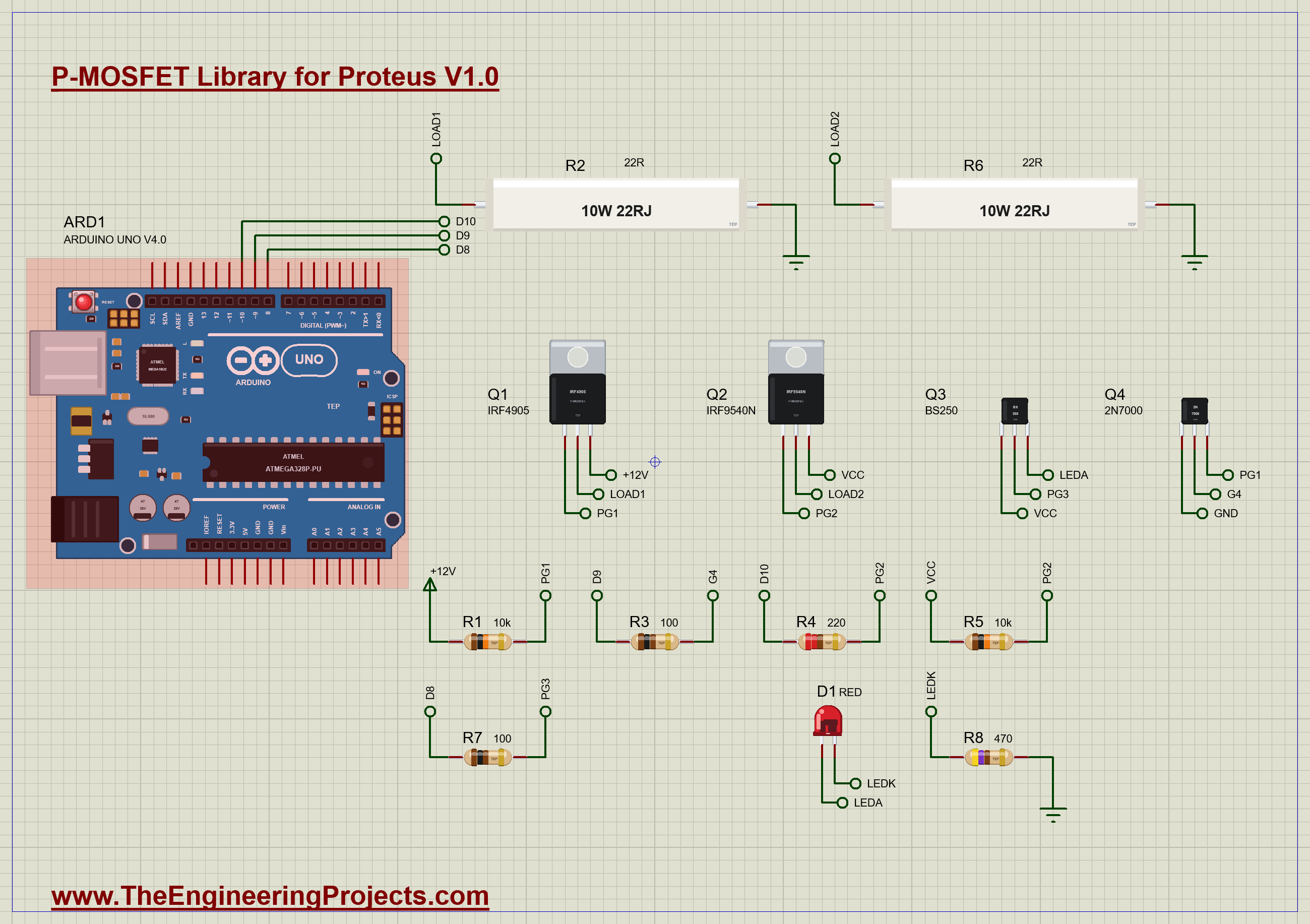
| Part | Connection | Job |
|---|---|---|
| Q1 IRF4905, R1 10k | S on +12V, G to PG1, D to LOAD1 | the 12 V high-side switch |
| Q4 2N7000, R3 100 | G from D9, D to PG1, S to GND | the level shifter |
| Q2 IRF9540N, R4 220, R5 10k | S on +5V, G from D10, D to LOAD2 | the 5 V high-side switch |
| R2, R6 (22 ohm, 10 W) | LOAD1 / LOAD2 to GND | the loads |
| Q3 BS250, R7 100 | S on +5V, G from D8, D to the LED | the small switch |
| D1, R8 470 | from the drain of Q3 to GND | the LED |
The Sketch
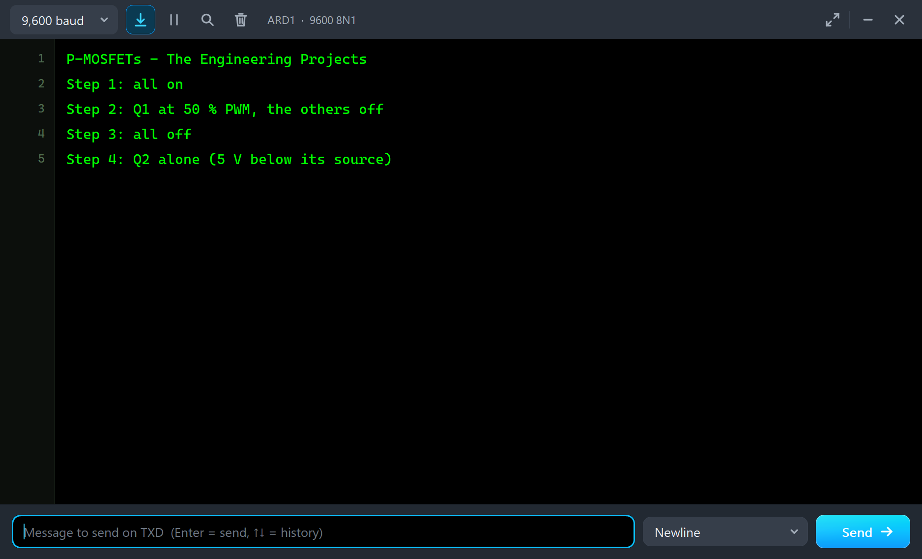
The sketch steps through four states, 2.5 s each, from three tables: the PWM duty of Q1 and the on and off states of Q2 and Q3:
const byte DUTY_1[4] = {255, 128, 0, 0};
const bool ON_2[4] = {true, false, false, true};
const bool ON_3[4] = {true, false, false, false};
At each step it writes the duty to the 2N7000 with analogWrite, so that 255 means Q1 fully on, and it pulls the gates of Q2 and Q3 LOW to turn them on:
    analogWrite(SHIFT, DUTY_1[step]);
    digitalWrite(GATE_2, ON_2[step] ? LOW : HIGH);
    digitalWrite(GATE_3, ON_3[step] ? LOW : HIGH);
Look at the two different senses: through the level shifter, HIGH turns the P-MOSFET on; driven directly, LOW turns it on. In setup the sketch writes the gates of Q2 and Q3 HIGH first, so they stay off until the first step.
Run the Demo
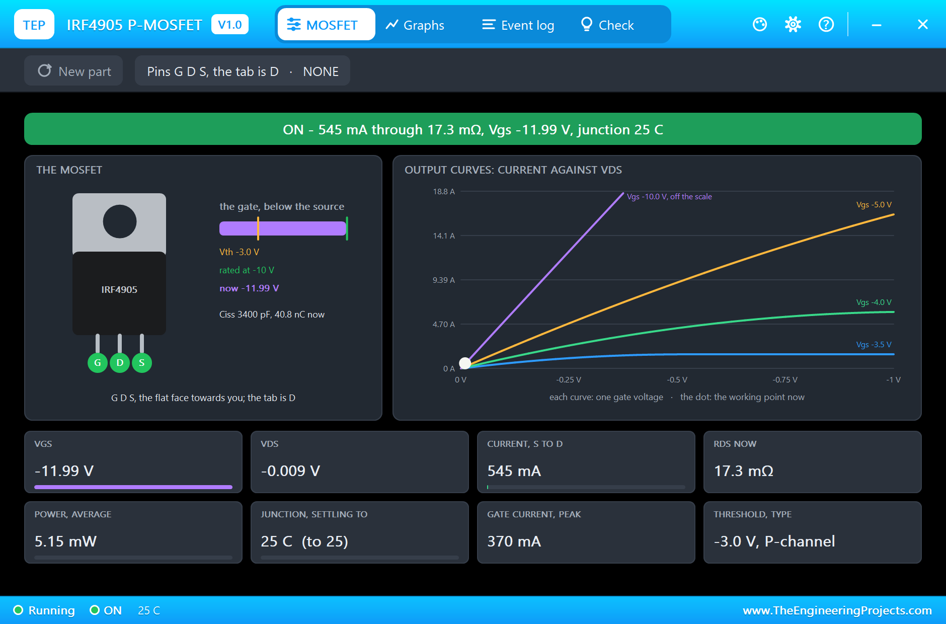
Press Run. In the first step everything is on. The 2N7000 pulls the gate of the IRF4905 to ground, 12 V below its source: Vgs -11.99 V. It carries 545 mA through 17.3 mΩ, only 9 mV across it and 5.2 mW of heat. The gate drive bar is full, and the dot sits at the very bottom left of its output curves, deep in the ohmic region. The gate current peaked at about 370 mA for a moment while the 2N7000 discharged its 3.4 nF:
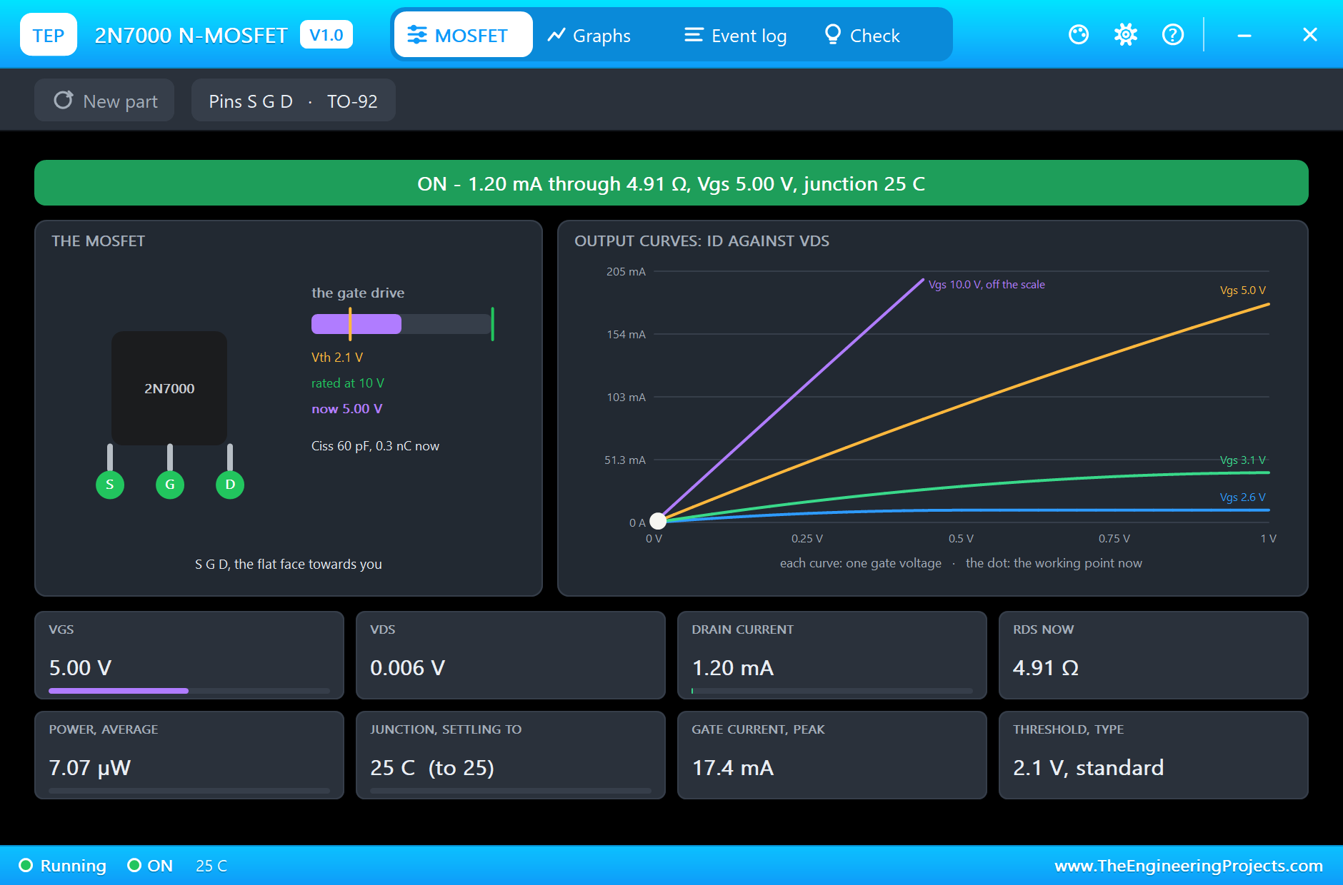
The 2N7000 is on with 5 V on its gate and carries only the 1.20 mA of the 10k pull-up, through 4.91 Ω. Its job is not current but voltage: it lets a 5 V pin pull a gate that lives on 12 V:
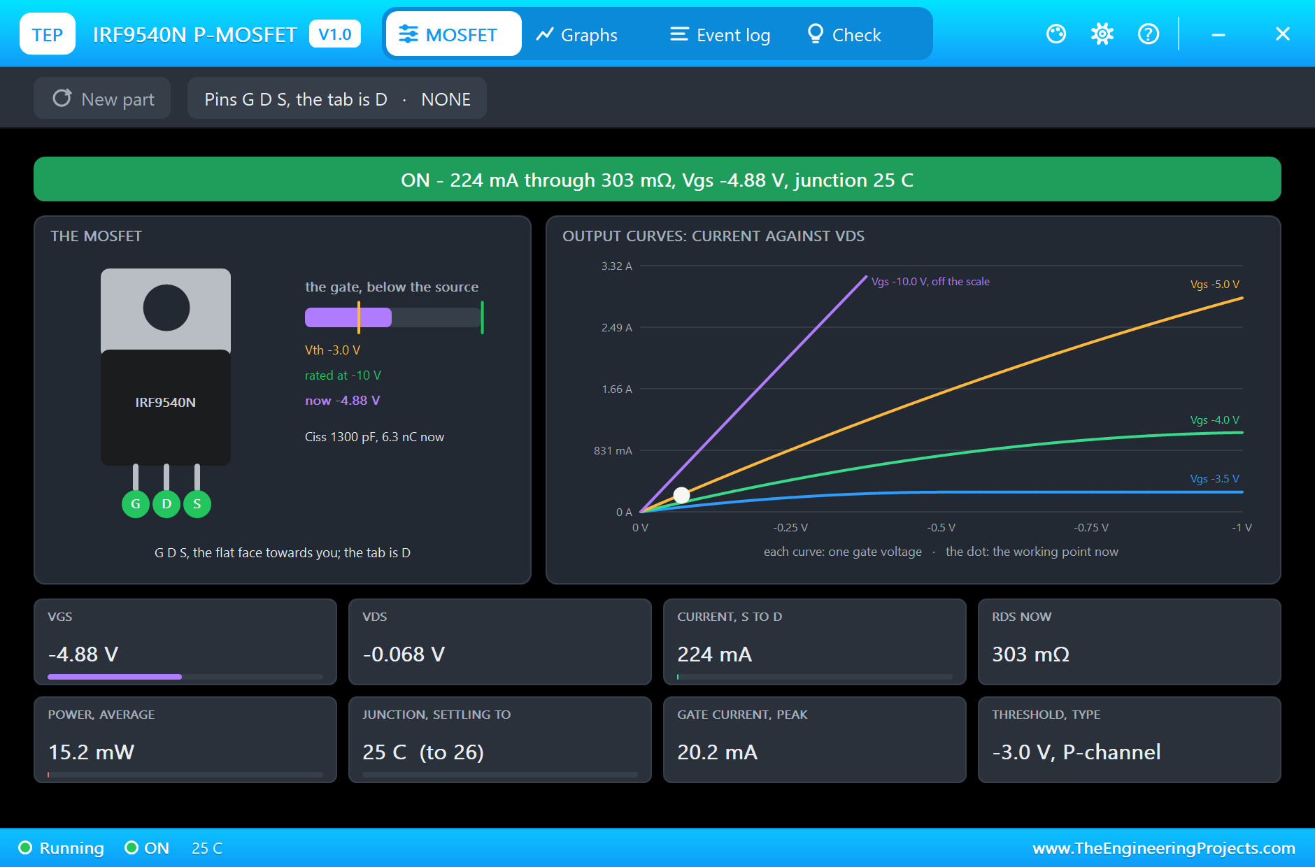
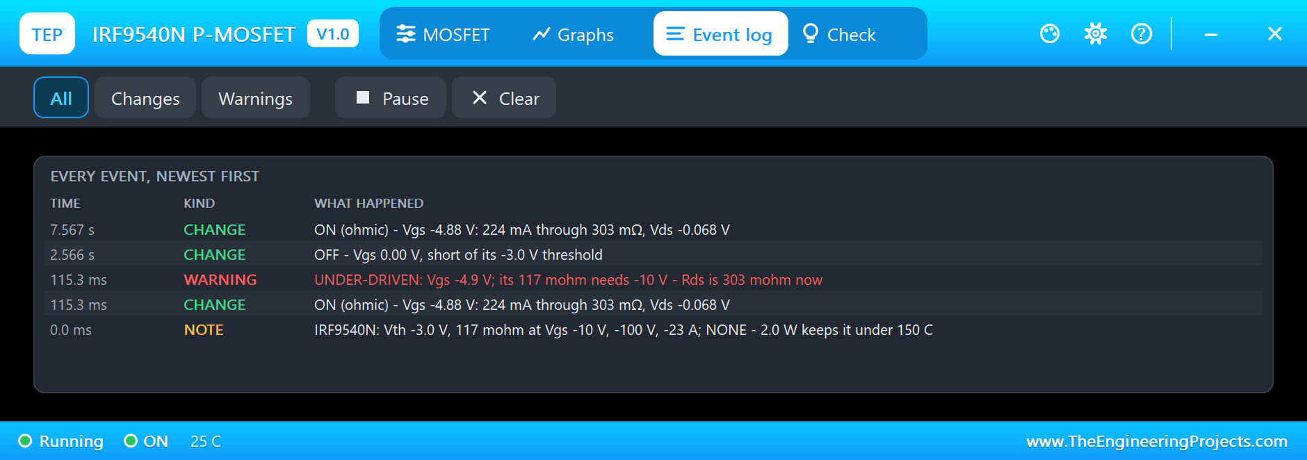
The IRF9540N gets its gate straight from the pin. With its source on 5 V, the most the pin can give is 5 V below the source: Vgs -4.88 V, after the small drop across R4 and R5. It carries 224 mA through 303 mΩ, against its rated 117 mΩ at -10 V, and its log warns UNDER-DRIVEN. At a quarter of an amp that costs only 15 mW; at 5 A it would cost 7.6 W:
Here is the complete circuit, truly running:
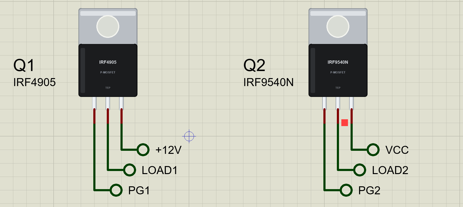
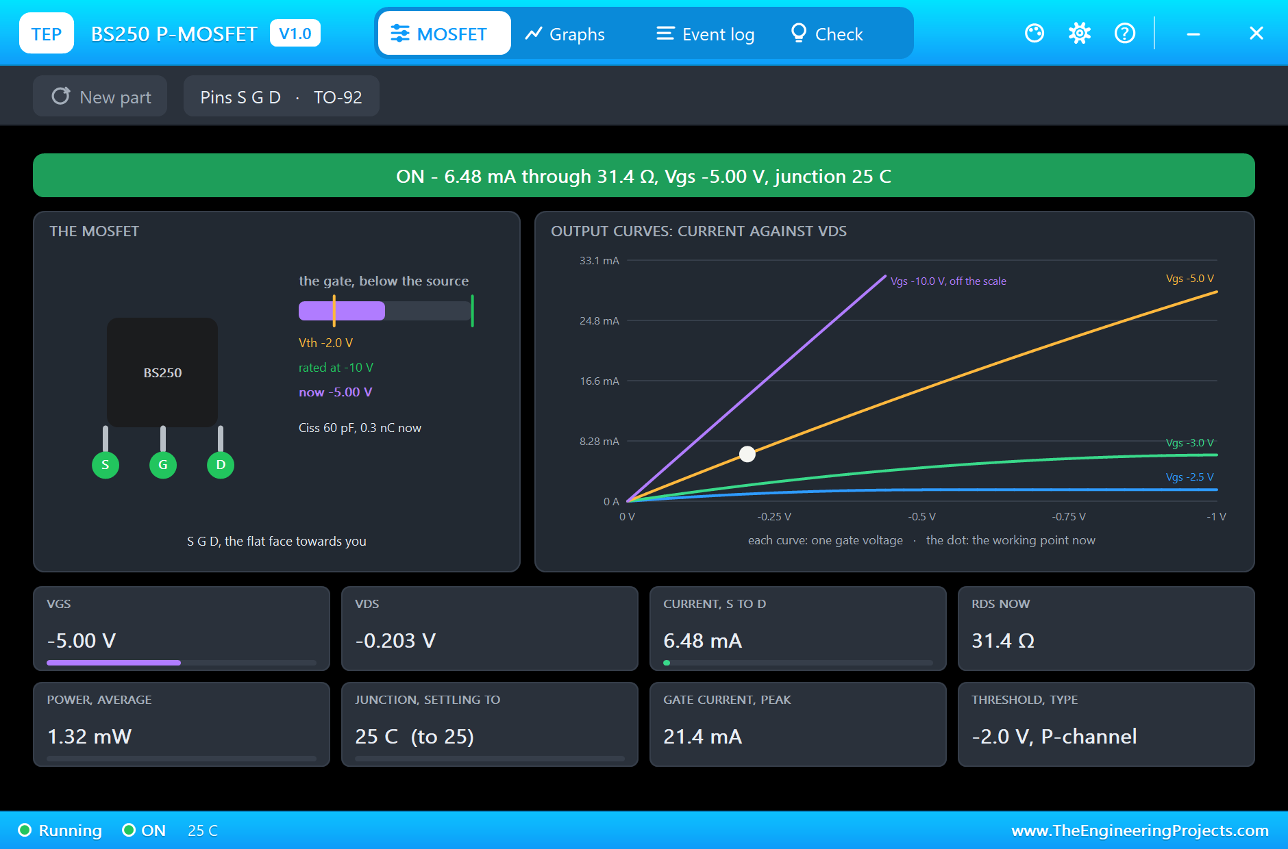
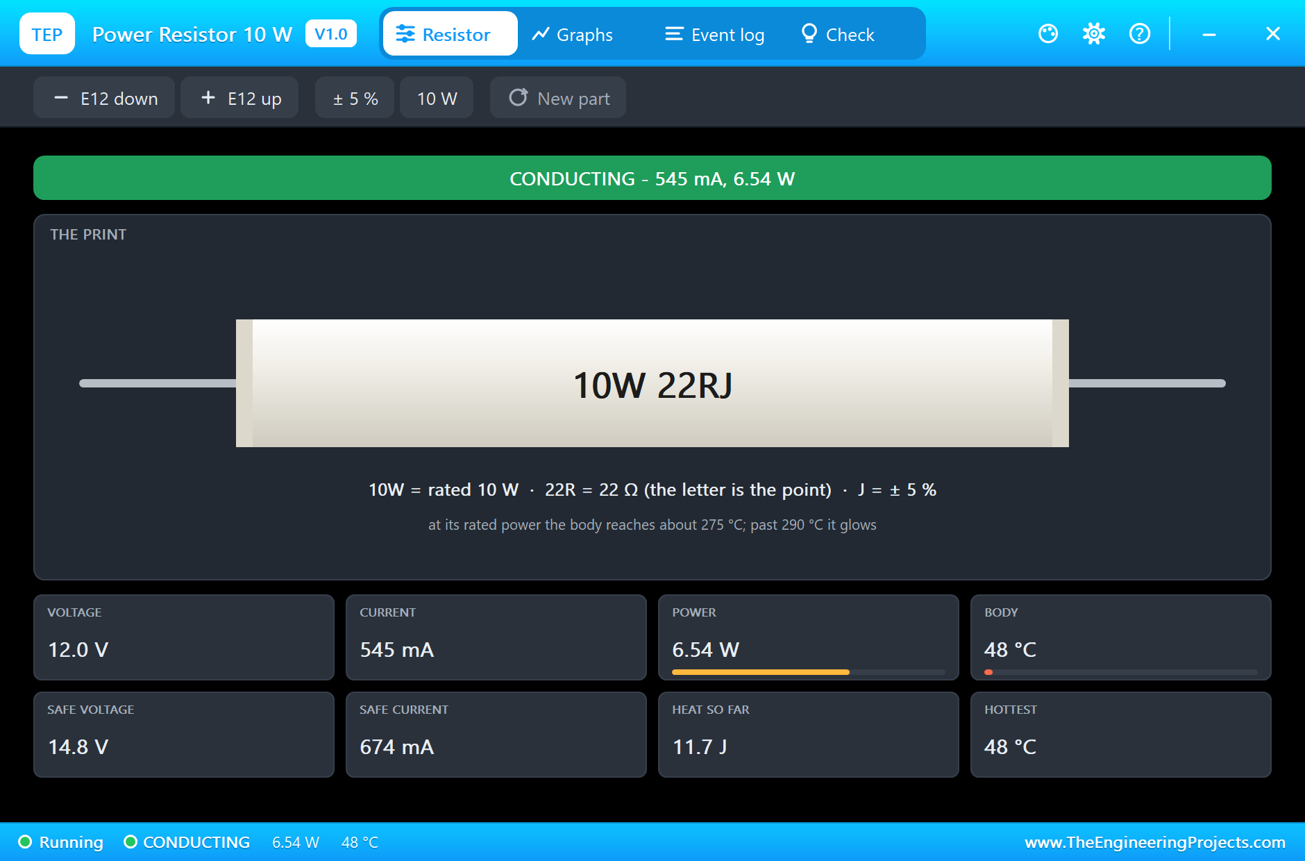
The BS250 lights the LED with 6.48 mA through 31.4 Ω. Its gate is also only 5 V below its source, but at a few milliamps the 0.2 V across it does not matter. The 12 V load takes 545 mA and 6.5 W of its 10 W rating:
PWM on the High Side
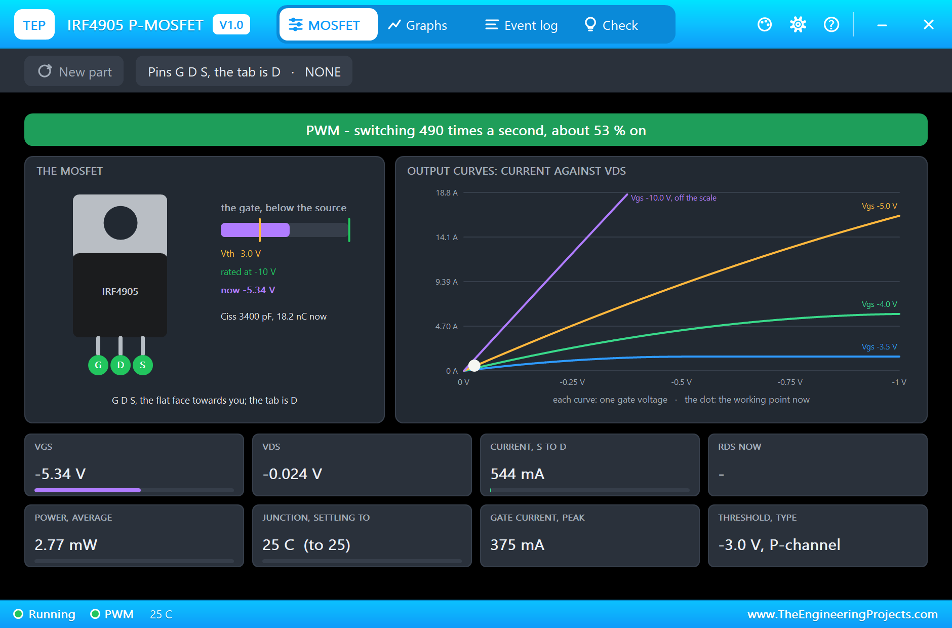
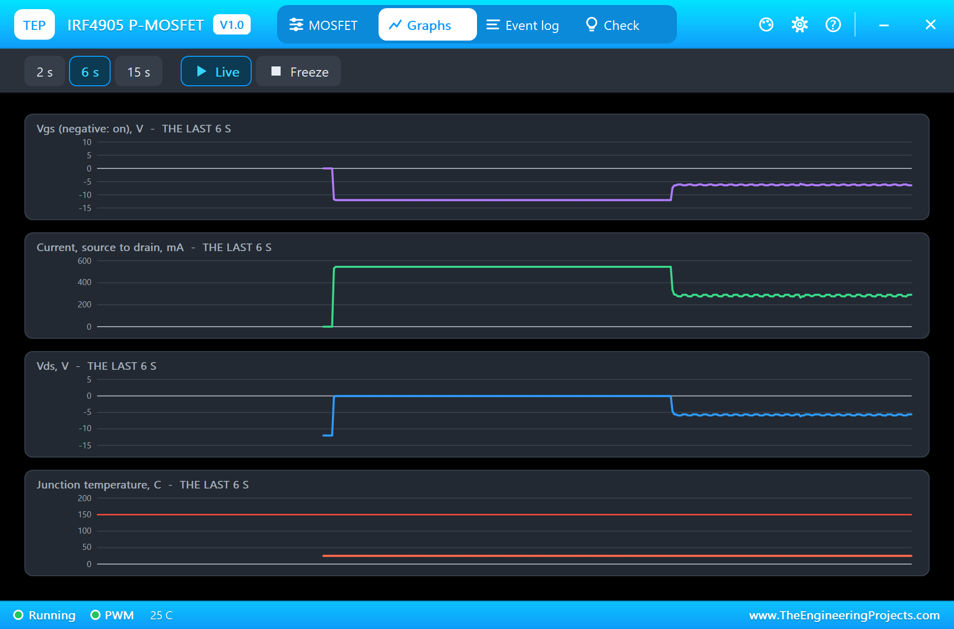
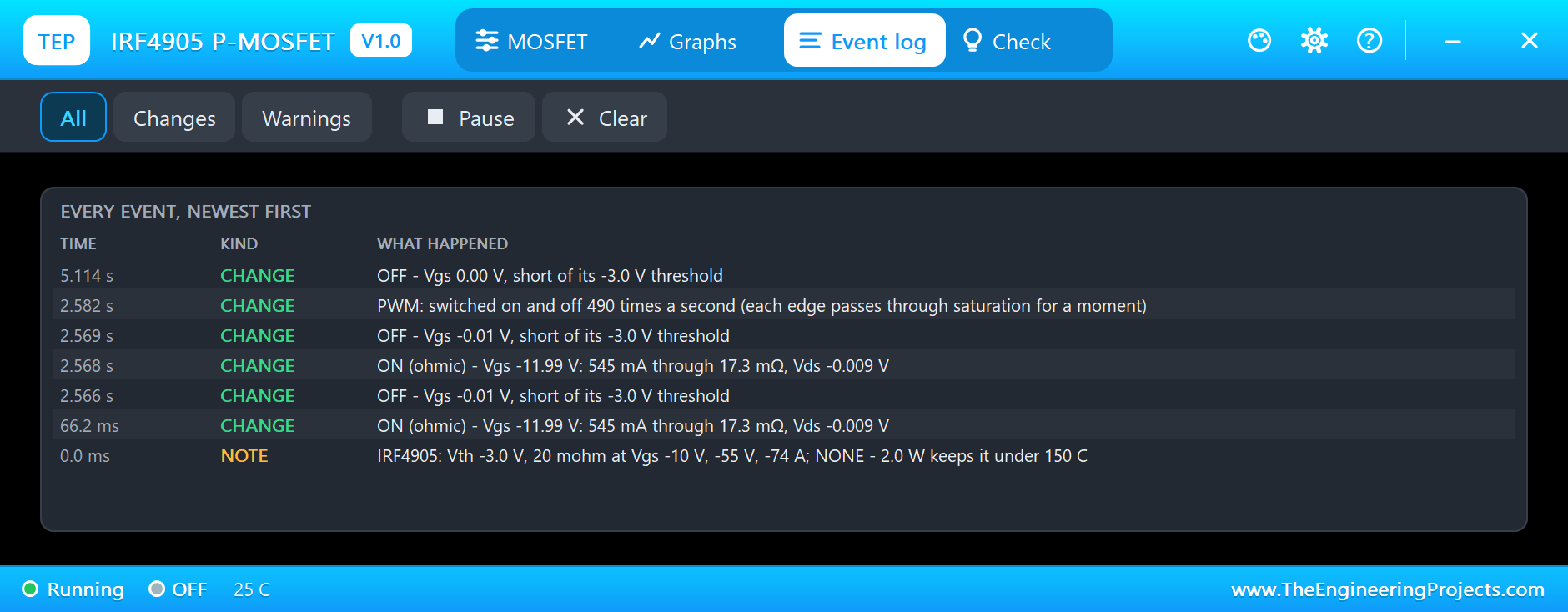
In the second step the 2N7000 gets a 50 % PWM signal, and the IRF4905 switches with it. The pop-up recognises it: PWM at 490 Hz, about 51 % on. The duty is a little over half because the 2N7000 pulls the gate down at once, while the 10k pull-up needs some tens of microseconds to bring the 3.4 nF gate back up to the source, so each pulse ends slightly late. The Graphs page shows Vgs, the current and Vds stepping from full on to the PWM average:
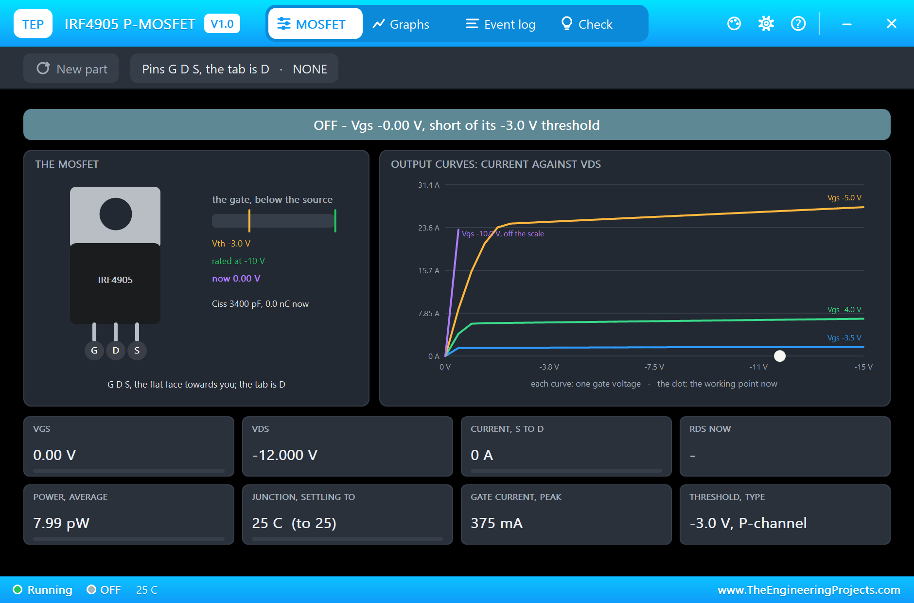
In the third step everything is off. The pull-up holds the gate of the IRF4905 at its source, Vgs 0.00 V, and the full -12 V sits across it:
The Logs and the Check Pages
The IRF9540N's Event log carries the warning in red: UNDER-DRIVEN, Vgs -4.9 V, its 117 mΩ needs -10 V. The IRF4905's log is clean: on, off, PWM, and off again:
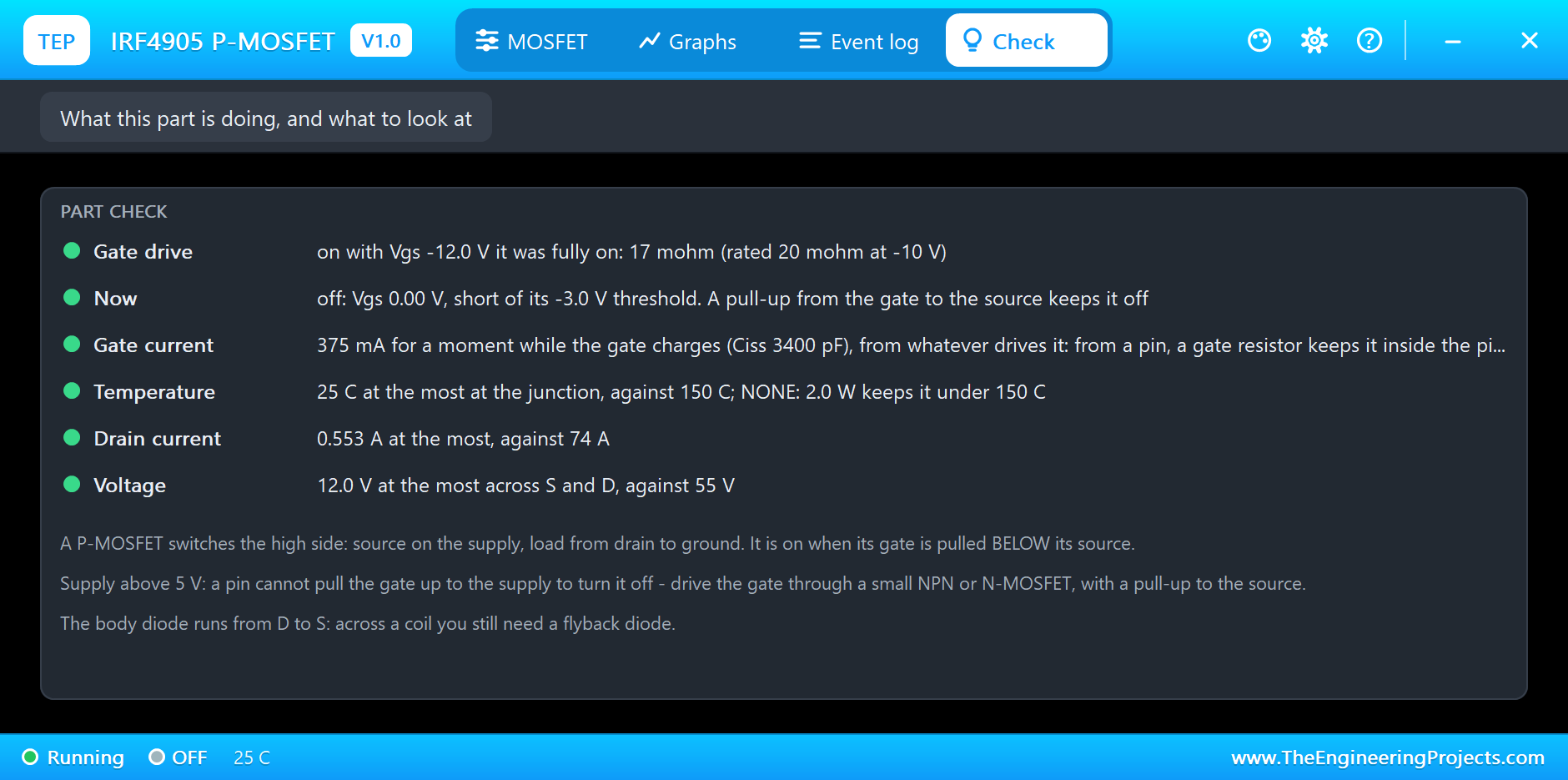
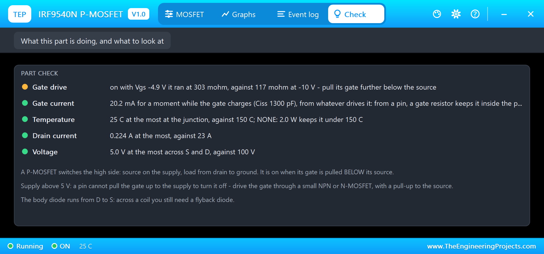
The Check pages keep the comparison after the parts switch off. The IRF4905's gate drive is green: with Vgs -12.0 V it was fully on, 17 mΩ against its rated 20 mΩ at -10 V. The IRF9540N's is amber: on with Vgs -4.9 V it ran at 303 mΩ against 117 mΩ, and it advises to pull its gate further below the source. Both report the gate charging current, 375 mA for the IRF4905 through the 2N7000 and 20 mA for the IRF9540N through its 220 Ω resistor:
Try It Yourself
- Remove the 2N7000 and wire D9 straight to the gate of the IRF4905 through a resistor, and see that it never turns off.
- Move Q2's source to +12V with a level shifter like Q1's, and watch its resistance fall towards 117 mΩ.
- Change R1 to 1k, and see the PWM duty come closer to 50 %, at the price of more current in the 2N7000.
- Change the loads to 2.2 Ω, and watch the under-driven IRF9540N heat up.
- Set Q1's heatsink to SMALL and push more current through it.
Ideas to Extend the Demo
- Switch the power of a sensor module on and off from the sketch to save energy.
- Build reverse polarity protection with the IRF4905 and a zener on its gate.
- Make an H-bridge with two P-MOSFETs on top and two N-MOSFETs below.
- Dim a 12 V LED strip on the high side with PWM through the level shifter.
Your Own Sketches
The demo sketch is in the zip file, and you can change it in the Arduino IDE. New to Arduino? Start with our Arduino Tutorial for Beginners. Export the compiled binary, and set the UNO's PROGRAM property to the new file. Our guide on How to get the HEX file from Arduino shows you where the file ends up.
Things to Know Before Using a Real P-MOSFET
- Think in Vgs, not in volts to ground: a P-MOSFET is on when its gate is pulled below its source.
- Use a level shifter above 5 V: a small NPN or N-MOSFET with a 10k pull-up from the gate to the source.
- Keep a pull-up on the gate: a floating gate can turn it half on.
- Mind the gate voltage limit: usually ±20 V; on higher supplies add a zener or a divider.
- Add a flyback diode across coils: the body diode is not one.
- Insulate the tab: on a TO-220 MOSFET it is the drain.
Troubleshooting
- UNDER-DRIVEN: the gate is not far enough below the source for its rated resistance; use a level shifter to pull it lower.
- It never turns off on a 12 V supply: a 5 V pin cannot reach the supply; drive the gate through an NPN or N-MOSFET with a pull-up.
- It turns on by itself: the gate floats; add a pull-up from the gate to the source.
- TOO HOT: the junction passed its limit; a heatsink, or a part with a lower Rds(on).
- The part is not simulated:
TEPPMOS.DLLis missing from MODELS and from the project folder.
Limitations of the Simulation
- The gate-drain capacitance and the Miller plateau are left out: the gate charges as one capacitor.
- Switching losses are not added to the heat.
- Avalanche and the safe operating area are not modelled.
- Arduino is a name of Arduino; this library is not made or endorsed by Arduino or Labcenter.
- Tested in Proteus 8.5 in November 2026 (the demo as shipped). Proteus 7 is not supported.
So, that was all about the P-MOSFET Library for Proteus. I hope it helps you switch the high side of your Arduino projects with confidence, and see why the gate must be pulled below the source before you build. If you have any questions, ask in the comments and I will help you out. Till the next tutorial, take care and have fun!

Comments
0