


74HC595 Shift Register Library for Proteus Simulation


Hello friends, I hope you all are doing great. Today, I am going to share the new 74HC595 Shift Register Library for Proteus Simulation, the sixth of the lab ICs in our University Lab series. If you have searched for a Proteus simulation of the 74HC595, this one shows what happens inside the chip, not only at its pins. The 74HC595 is the classic way to get more outputs from a microcontroller: three pins drive eight outputs, and chained chips drive 16, 24 or more. LED bars, seven-segment displays, LED matrices and relay boards all use it, and digital-electronics courses use it to teach shift registers, latches and serial data.
74HC595 Shift Register Library for Proteus Simulation
Latest version: V1.0 (November 2026, this tutorial)
Helping Tools
- Serial Monitor Advance: a serial terminal window for the UART of your board
- Serial Monitor Expert: the serial monitor with extra debugging tools
- LCD Library for Proteus V3.0: 16x2, 20x4 and I2C LCDs to show your readings
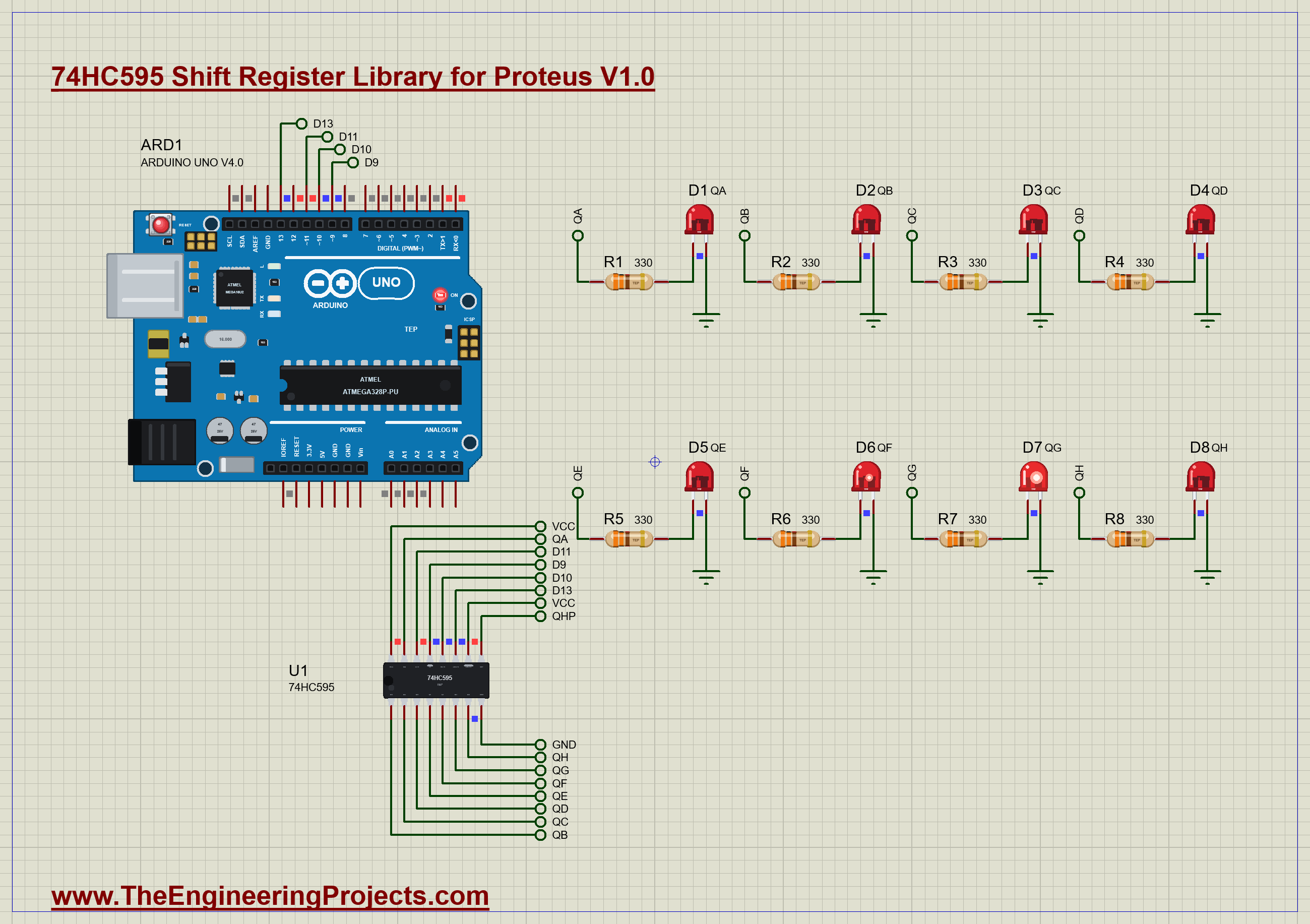
Our library brings the real chip into your Proteus simulation: the 74HC595 in its PDIP-16 package, drawn at its true size of 19.3 x 6.35 mm. The simulation model follows TI's datasheet. It has the shift register and the storage register, OE and SRCLR, and QH' for chaining. The outputs are real CMOS drivers, so every LED draws a real current and the chip's current limits show up. The timing is checked against the datasheet too. The pop-up shows both registers bit by bit and draws the last 24 clocks. The demo is an Arduino driving eight LEDs, first with shiftOut() and then with SPI. It lights all eight at once, which turns out to be just over the chip's limit, and dims them with OE.
NOTICE: Our team has put a lot of effort into these small parts: the bodies, the animation and the pop-ups are all our own design, and you get them free. Your feedback is the fuel that keeps us going, so please tell us what you think in the comments below or in the 74HC595 board of our forum. And if our free libraries help you, you can buy us a coffee. So, let's get started with the 74HC595 Shift Register Library for Proteus Simulation:
What is the 74HC595?
The 74HC595 is an 8-bit serial-in, parallel-out shift register with output latches, in the 74HC high-speed CMOS family. You feed it one bit at a time on a single data pin, clock each bit in, and then, with one more pulse, all eight bits appear together on its eight outputs. Between updates the outputs hold still, however long the next byte takes to arrive. That second register, the latch, is what makes the 595 better than a plain shift register: the LEDs never flicker through the bits as they pass.
| SN74HC595 (25 °C) | |
|---|---|
| Supply | 2 V to 6 V; 8 uA quiescent (maximum) |
| Shift clock | up to 31 MHz at 4.5 V (25 MHz over -40 to 85 °C), 5 MHz at 2 V |
| Outputs QA - QH | 4.3 V at -6 mA and 0.17 V at 6 mA from 4.5 V (typical) |
| Output current | 35 mA per output, 70 mA through VCC or GND (absolute maximum) |
| Set-up times | SER 25 ns before SRCLK rises; SRCLK 19 ns before RCLK |
| Inputs | high above 3.15 V, low below 1.35 V at 4.5 V |
The Pins
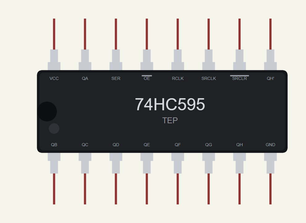
Pins 1 to 7 are QB to QH, pin 8 is GND, 9 is QH', 10 is SRCLR (active low), 11 SRCLK, 12 RCLK, 13 OE (active low), 14 SER, 15 QA and 16 VCC. Our drawing lies on its side with the notch on the left: QB to QH and GND along the bottom, VCC, QA and the control pins along the top, with bars over OE and SRCLR. In the netlist QH' is called QHP.
Two Registers
The shift register. On every rising edge of SRCLK, each of its eight stages takes the value of the one before it: QA takes SER, QB takes the old QA, and so on to QH; the old QH falls out to QH'. Eight clocks load a whole byte. With shiftOut() in MSBFIRST order, the first bit sent ends up on QH. SRCLR low empties the shift register at once.
The storage register. On a rising edge of RCLK it copies the shift register, all eight bits at the same moment, and only it drives the outputs. If SRCLK and RCLK rise together, it copies the shift register as it was before that shift, so it stays one clock behind, as the datasheet notes.
The outputs. OE low connects the storage register to QA - QH; OE high leaves them floating, without losing the byte. QH' is not affected by OE: it always shows the last stage of the shift register, ready for the next chip's SER.
Features of the 74HC595 Shift Register Library for Proteus Simulation
- The real chip at true scale: the PDIP-16, 19.3 x 6.35 mm, with its real pinout.
- Both registers from the datasheet: shifting on SRCLK, latching on RCLK (one clock behind on shared edges), SRCLR, OE and QH'.
- Real outputs: 30 Ω CMOS drivers to VCC and GND, so every load draws a real current and the output voltage sags with it.
- Limits reported: 35 mA per output and 70 mA through VCC; the set-up times; the clock against the supply voltage.
- Clean edges: every output change places a breakpoint in the analog simulation, so the LEDs switch at the clock edge itself.
- A pop-up: both registers bit by bit, the eight outputs with volts and milliamps, the last 24 clocks, graphs, an event log and a check page.
- A complete package: about 1.9 MB with the library, our resistor and LED parts, our Arduino UNO V4.0 and the demo, without the source code of the model.
The 74HC595 in Proteus
The device is SN74HC595TEP in TEPHC595.LIB, under Lab ICs > Logic, with the prefix U and the mixed-mode model TEPHC595.DLL: SER, SRCLK, RCLK, SRCLR and OE are digital inputs, the outputs are analog. Search 74HC595 in Pick Devices. Its one property, RON, is the output resistance of QA - QH in ohms (30 by default, from the datasheet's 4.3 V at 6 mA); QH' gets 1.5 times as much.
Download 74HC595 Shift Register Library for Proteus Simulation
Click the button below to download 74HC595-Shift-Register-Library-for-Proteus-v1.0.zip (about 1.9 MB, without the source code of the models):
74HC595 Library for Proteus V1.0- README.txt: installation, the demo, the wiring, troubleshooting and the limits of the simulation.
- Proteus Library Files:
TEPHC595.LIB, ourTEPRESISTOR.LIB,TEPLED5MM.LIBandArduinoV4TEP.LIB. - Proteus Model Files:
TEPHC595.DLL,TEPRESISTOR.DLL,TEPLED5MM.DLLandTEPARDUINO.DLL. - Arduino Code: the demo sketch.
- Proteus Simulation: the demo project, its HEX file and copies of the DLLs.
No Proteus yet? Read How to Download and Install Proteus 7 and 8. New to libraries? Follow How to Install a New Library in Proteus.
How to Install 74HC595 Shift Register Library for Proteus Simulation
- Close Proteus and extract the whole zip file, for example to your Desktop.
- Copy the files from Proteus Library Files into the LIBRARY folder of Proteus.
- Copy the files from Proteus Model Files into the MODELS folder.
- Delete
TEPHC595.IDXfrom the LIBRARY folder if it is there. - Start Proteus, press P and search for 74HC595.
Proteus Simulation of Eight LEDs on Three Pins
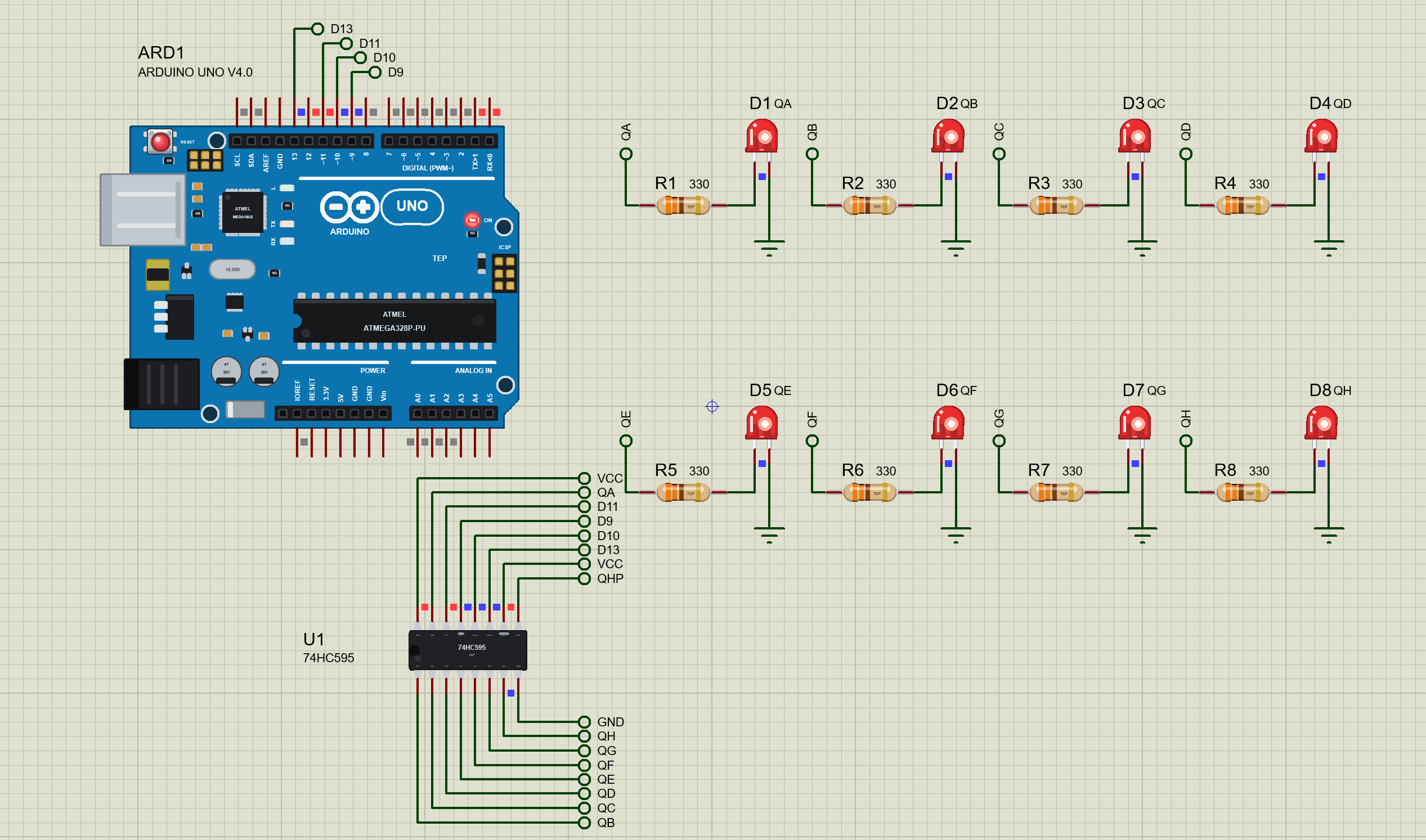
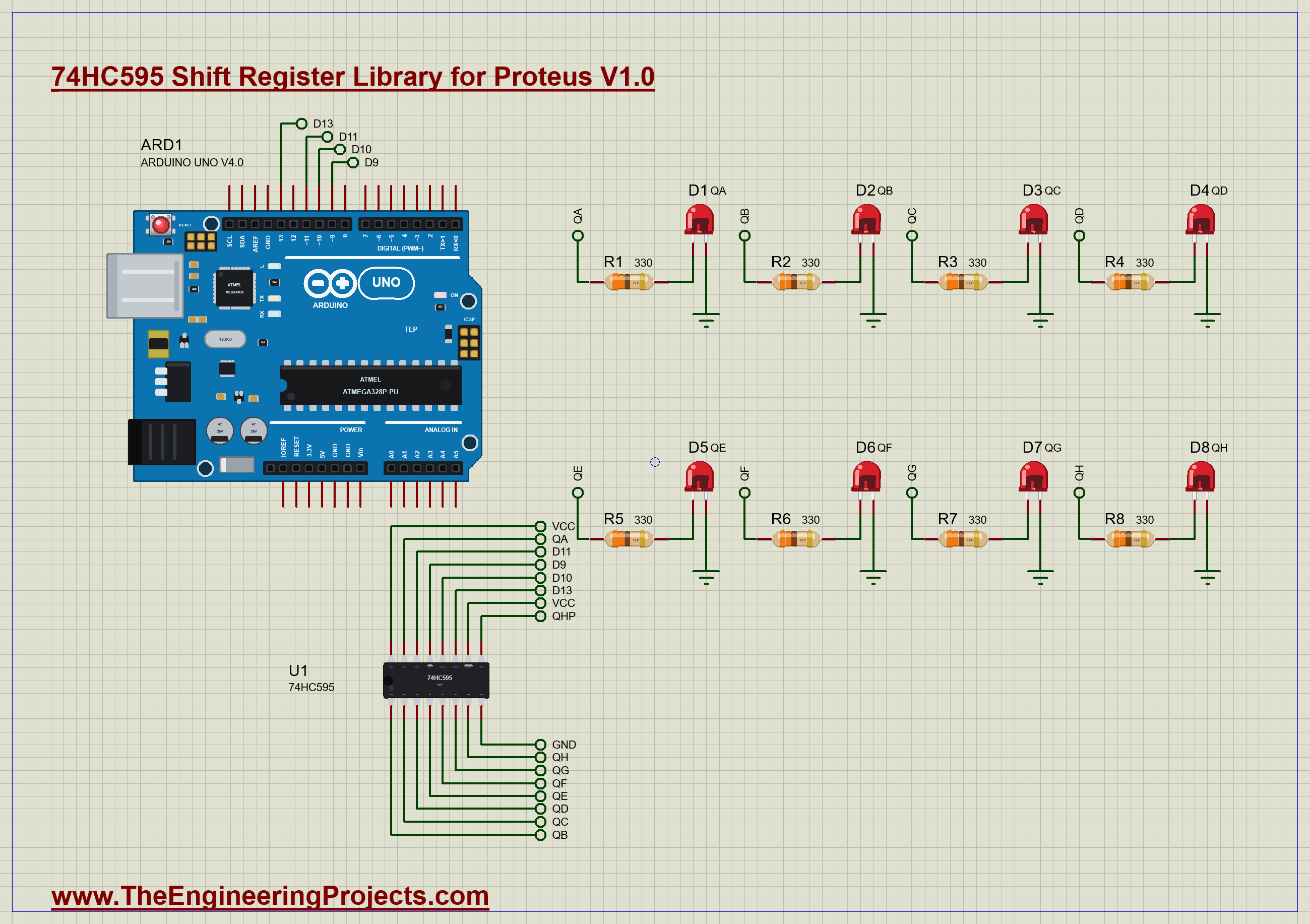
The demo has our Arduino UNO Library for Proteus V4.0 with its built-in monitor, the same window as our TEP Serial Monitor Advance for Proteus, the 74HC595 on 5 V and eight of our red 5 mm LEDs, each through a 330 Ω resistor from QA to QH. SER goes to the UNO's D11, SRCLK to D13 and RCLK to D10: those are the UNO's hardware SPI pins (MOSI, SCK and SS), so the same wiring works with shiftOut() and with SPI. OE goes to D9, a PWM pin, and SRCLR is tied to 5 V. Open 74HC595-LEDs-ArduinoUnoV4.pdsprj.
The Sketch
Three small functions do all the work: a pulse on RCLK, a byte by shiftOut(), and a byte by SPI:
void latch() { digitalWrite(LATCH, HIGH); digitalWrite(LATCH, LOW); }   // RCLK rises: QA - QH change together
void byShiftOut(byte b) { shiftOut(DATA, CLK, MSBFIRST, b); latch(); }
void bySPI(byte b) { SPI.transfer(b); latch(); }
shiftOut() wiggles the pins in software. SPI uses the UNO's hardware, set to 4 MHz:
SPI.begin(); SPI.beginTransaction(SPISettings(4000000, MSBFIRST, SPI_MODE0));And the brightness of all eight LEDs comes from one PWM on OE:
analogWrite(OE_PIN, 192); Serial.println("OE PWM 75 % high: LEDs at 25 %");The sketch walks one bit across the outputs, sends 0xA5 with shiftOut() and 0x3C with SPI, each timed with micros(). Then it sends 0xFF, dims, switches off and on again with OE, and finally runs a light back and forth, Knight Rider style, by SPI.
74HC595 Simulation Results
Open the project and press Run. The demo runs about 9.5 simulated seconds, which Proteus ran in about three minutes on our PC with the pop-up open. Click the chip to open its pop-up; every number below comes from one simulation run, the demo exactly as it ships.
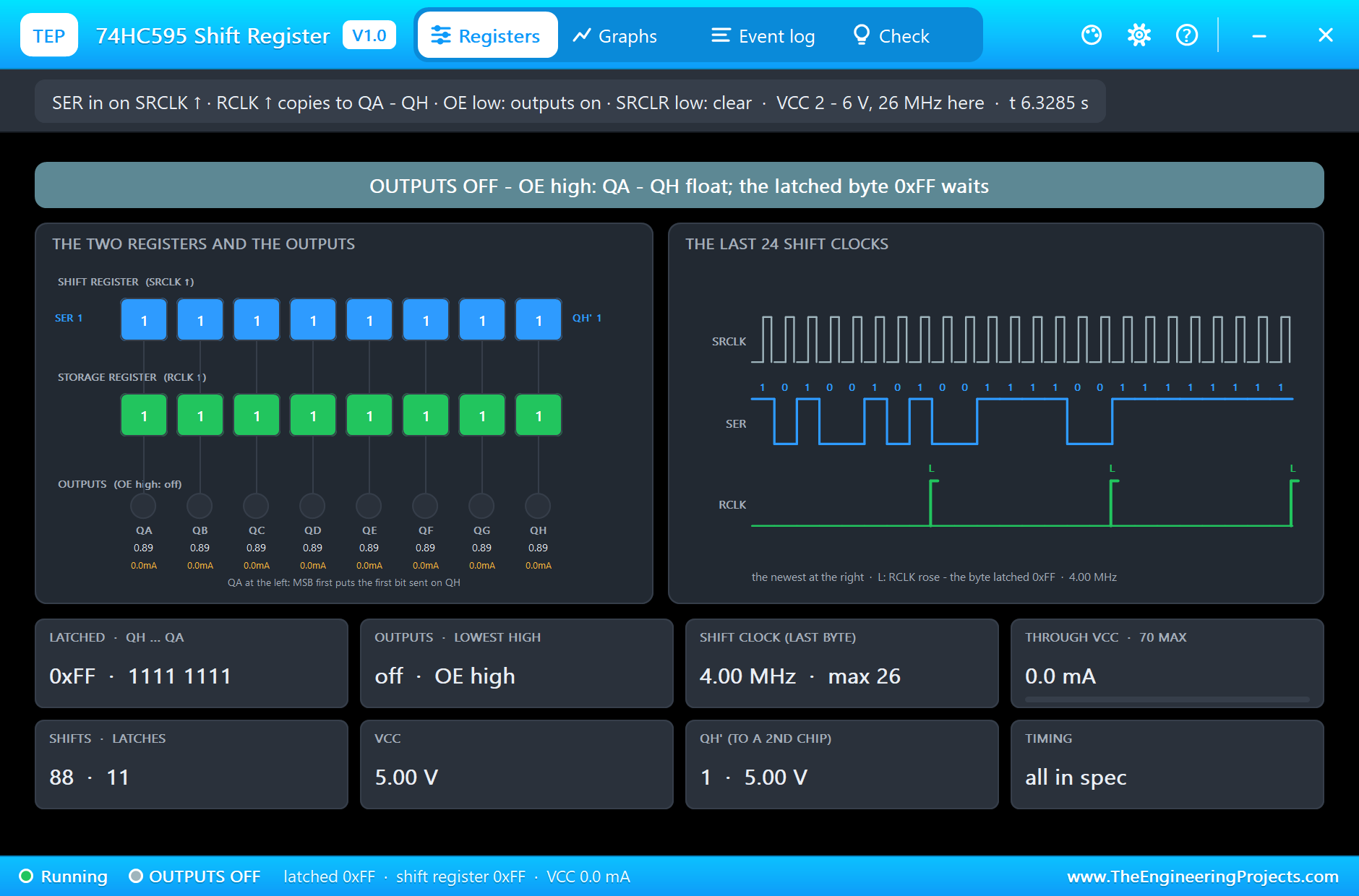
shiftOut(): 0xA5
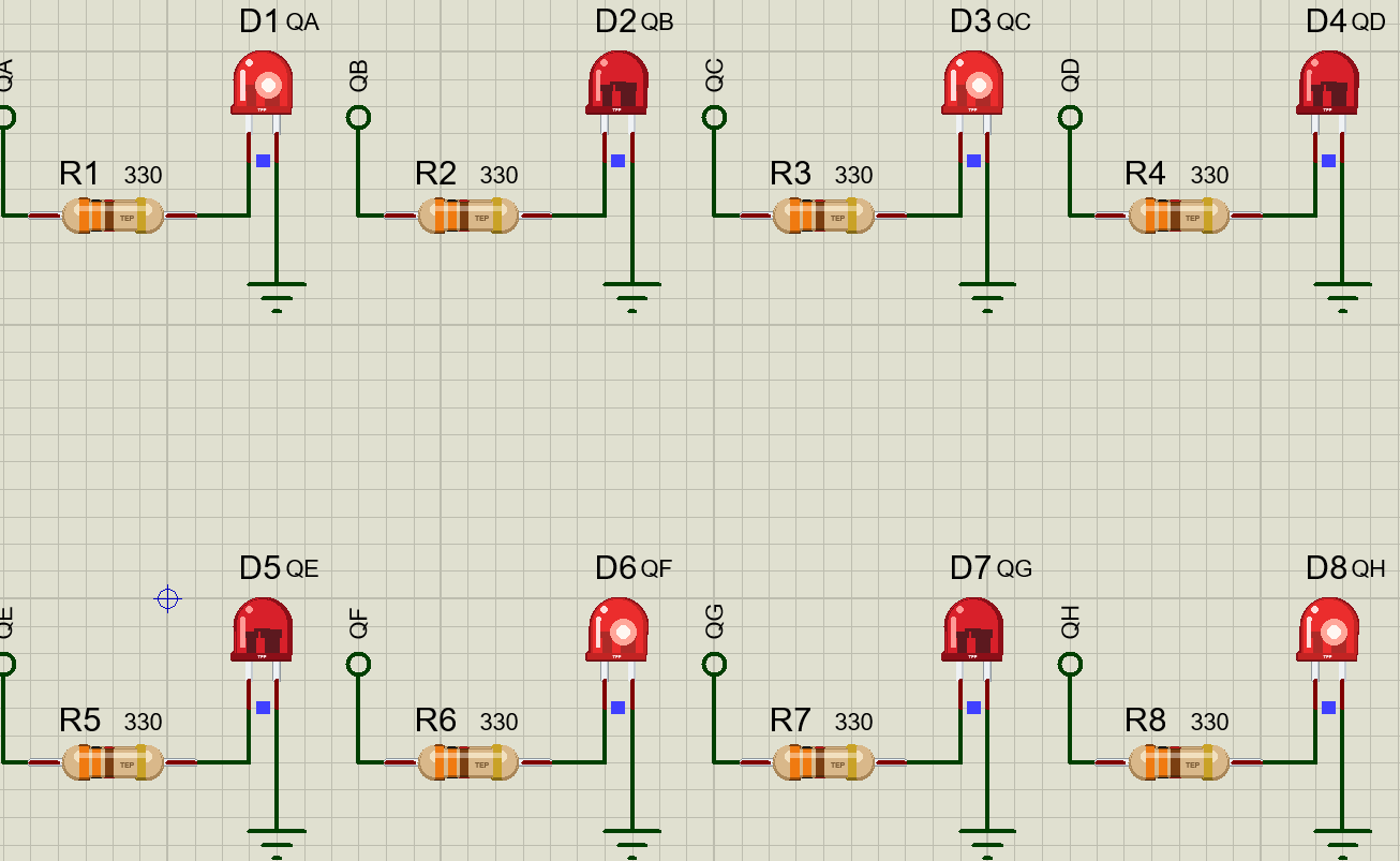
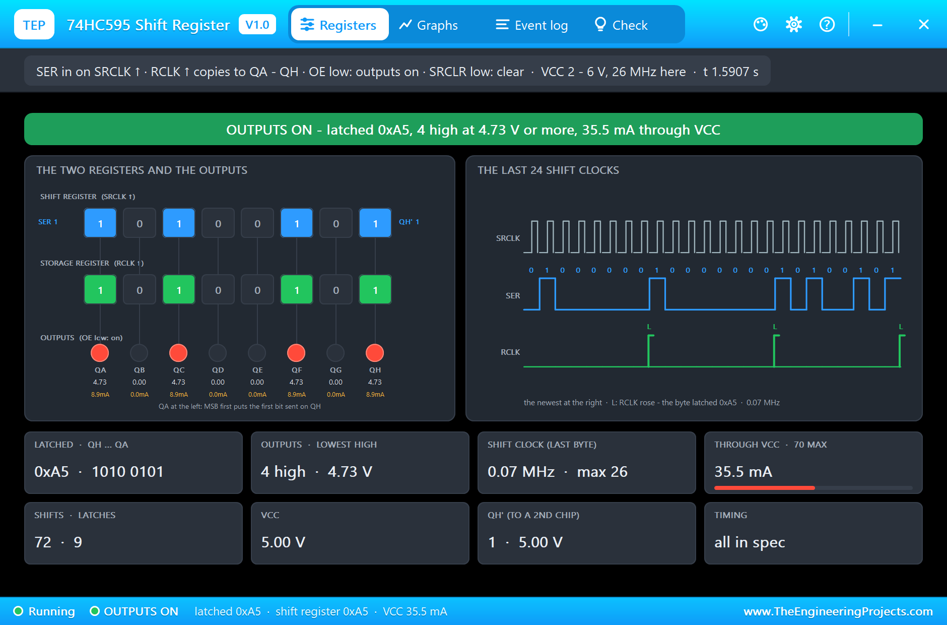
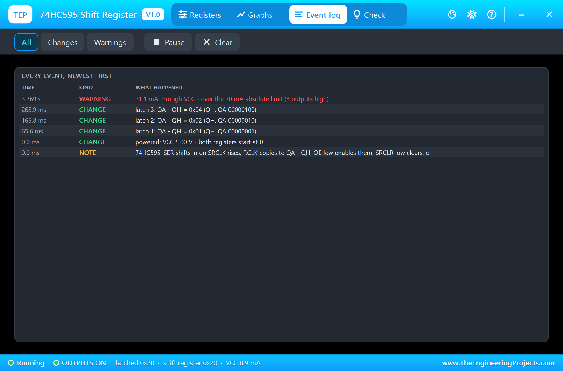
The walking bit latches 0x01, 0x02, 0x04 and so on, one LED after another; the Event log notes the first latches at 65.6, 165.8 and 265.9 ms. Then 0xA5, binary 10100101, lights QA, QC, QF and QH. Each lit LED draws 8.9 mA, and its output sits at 4.73 V: 5 V minus 8.9 mA through the 30 Ω driver. Four LEDs take 35.5 mA through the VCC pin.
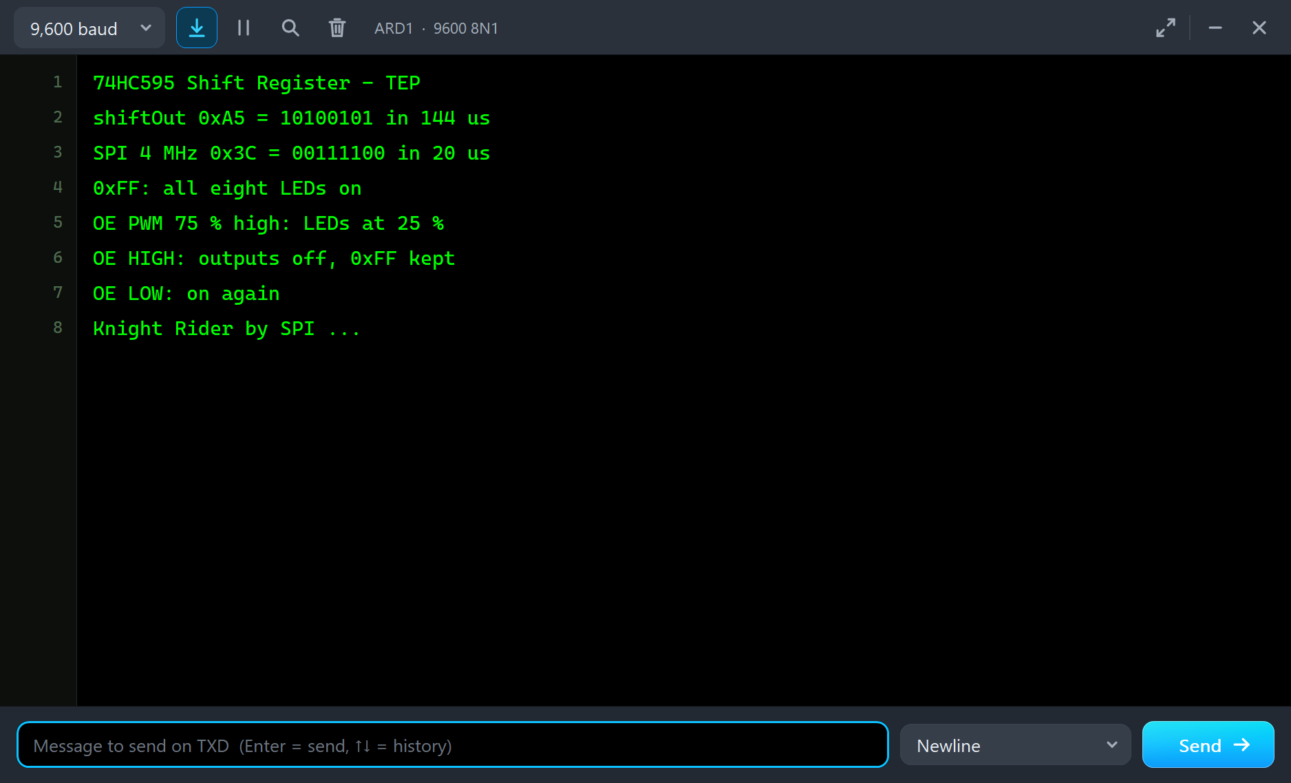
The pop-up shows the byte in both registers and draws the last 24 clocks, the SER bit at each rising edge of SRCLK and the RCLK pulse after the eighth. It measured the software clock of shiftOut() at 0.065 MHz, about 65 kHz. The monitor says the whole byte, with its latch, took 144 us.
SPI at 4 MHz: 0x3C
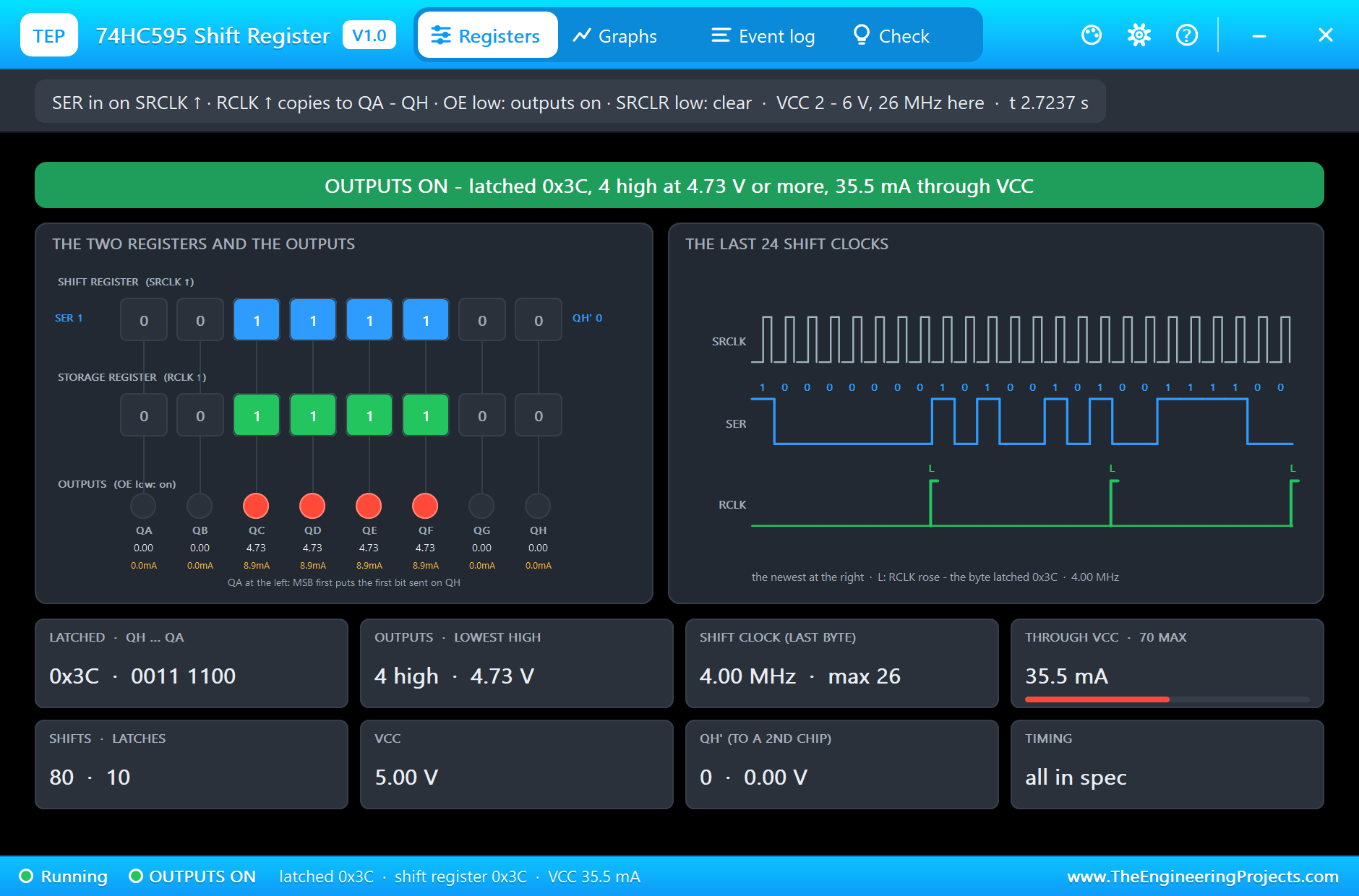
With SPI the clock runs at exactly 4.000 MHz in the simulation, far inside the 26 MHz the chip allows at 5 V, and the Timing tile says all in spec. The byte 0x3C, 00111100, now takes 20 us in total. The clock is 60 times faster than shiftOut(), but the byte is only about 7 times faster: the eight bits themselves take 2 us, and most of the 20 us goes to the two digitalWrite() calls of the latch. The clock diagram shows the last three bytes in a row: 0x80, the end of the walking bit, then 0xA5 from shiftOut() and 0x3C from SPI.
All Eight On: the 70 mA Limit
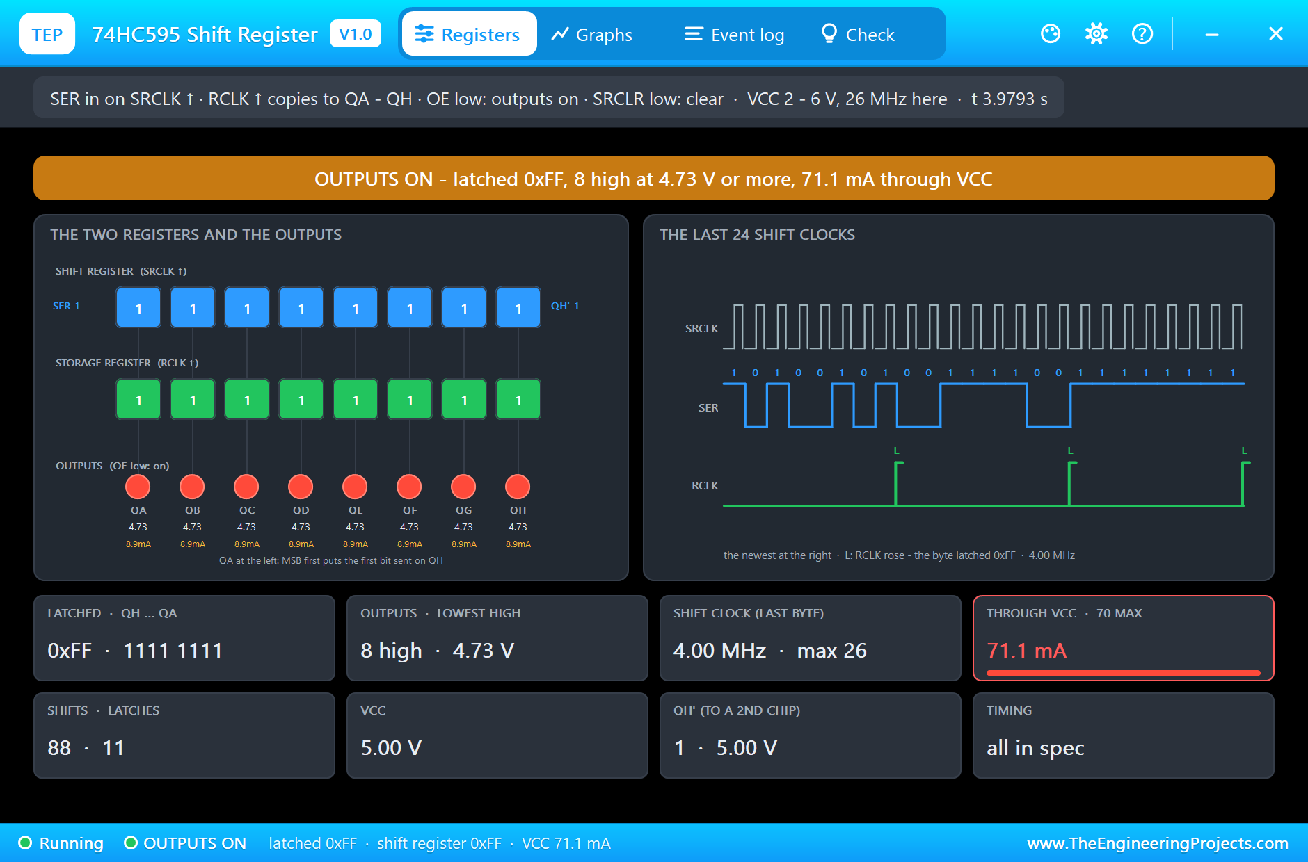
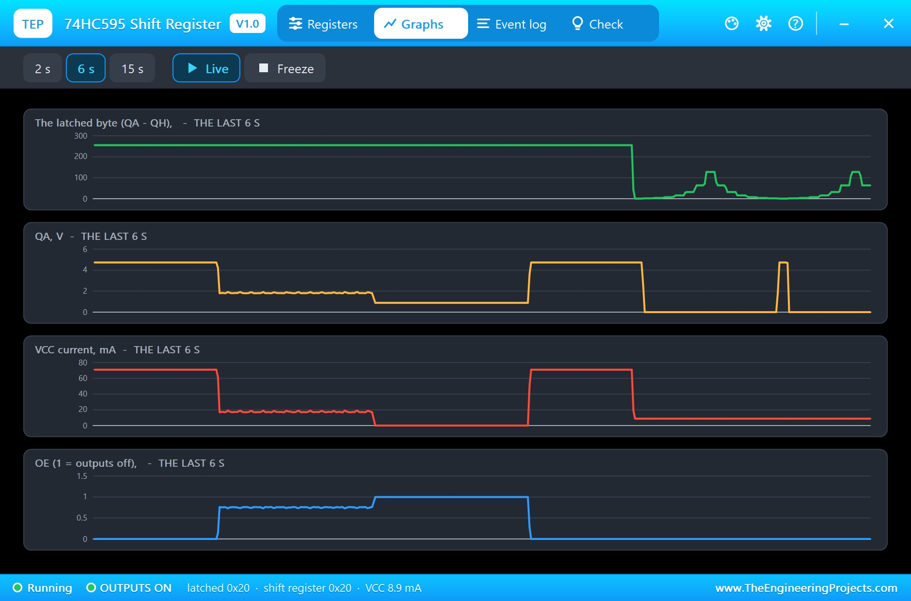
Now 0xFF. Every output is high at 4.73 V, every LED takes 8.9 mA, and the VCC pin carries 71.1 mA. The datasheet allows 35 mA per output but only 70 mA through VCC or GND in total, so eight modest LEDs are already over the absolute limit. The pop-up's banner turns orange, the VCC tile turns red, and the Event log records it. The chip would probably survive, but it is not a design to build. Larger resistors, a 74HC595 per four LEDs, or a driver such as the ULN2003 fix it.
OE: Dimming and Switching Off
analogWrite(9, 192) puts a 490 Hz PWM on OE, high 75 % of the time. Because OE is active low, the outputs are on only 25 % of the time, and all eight LEDs dim together. That one PWM pin is the classic way to set the brightness of a whole 595 display. Then OE goes high and stays high: QA - QH float, the LEDs go out, and only 8 uA flows through VCC. The storage register still holds 0xFF, and when OE goes low again the LEDs come straight back.
Knight Rider, the Graphs, the Log and the Check Page
From 7.7 s a single light runs back and forth by SPI; by 9.5 s the chip has counted 280 shifts and 35 latches. The Graphs page plots the latched byte, QA's voltage, the VCC current and OE over the last 2, 6 or 15 simulated seconds: the PWM shows as a dense block on OE, and the all-on phase as a 71.1 mA step in the VCC current.
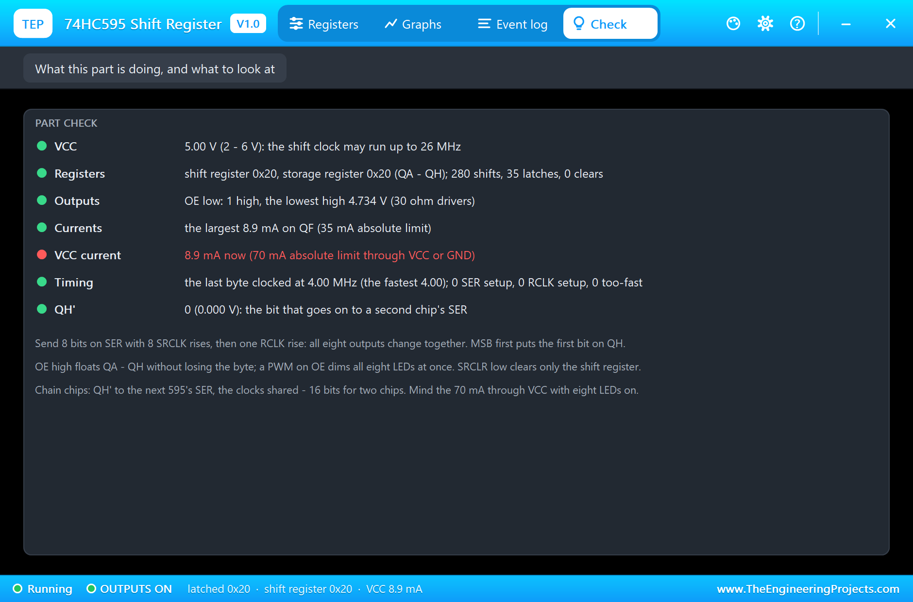
The Check page sums up the chip: the supply and the clock it allows, both registers with the counts, the outputs, the largest output current, the VCC current against 70 mA, the timing, and QH'.
Try It Yourself
- Change shiftOut() to LSBFIRST and see the walking bit run the other way.
- Raise the eight resistors to 680 Ω and send 0xFF: the VCC current falls below 40 mA.
- Pull SRCLR low for a moment from a spare pin: the shift register clears, the LEDs keep their byte until the next latch.
- Tie RCLK to SRCLK and watch the storage register stay one clock behind.
- Set RON to 60 and see the output voltage sag more with the same LEDs.
- Run the chip from 3.3 V and compare the LED current and the clock it allows.
Ideas to Extend the Demo
- Chain a second 74HC595 from QH' and send 16 bits for 16 LEDs.
- Drive a seven-segment display, one segment per output.
- Build an 8 x 8 LED matrix with two 595s, one for the rows and one for the columns.
- Switch relays or motors through a ULN2003 driver on the outputs.
Your Own Sketches
The demo sketch is in the zip file, and you can change it in the Arduino IDE. New to Arduino? Start with our Arduino Tutorial for Beginners. Export the compiled binary, and set the UNO's PROGRAM property to the new file. Our guide on How to get the HEX file from Arduino shows you where the file ends up.
Things to Know Before Using a Real Chip
- Watch the total current: 70 mA through VCC or GND for the whole chip; eight LEDs at 9 mA are already at the limit.
- Never leave OE or SRCLR open: tie OE to GND (or a PWM pin) and SRCLR to VCC; open CMOS inputs are undefined.
- Decouple it: 100 nF across VCC and GND, close to the chip.
- Long chains: share the clocks and buffer them; the timing and the wiring matter more as the chain grows.
Troubleshooting
- NO SUPPLY: VCC is under 1.5 V; a warning appears outside 2 to 6 V.
- No LED lights: OE is high or open, or RCLK never rises after the eight bits.
- The bits are reversed: MSBFIRST puts the first bit on QH; use LSBFIRST for the opposite order.
- Over 70 mA through VCC: too many outputs loaded at once; use larger resistors or a driver.
- A set-up warning: SER changed less than 25 ns before SRCLK rose.
- The part is not simulated:
TEPHC595.DLLis missing from MODELS and from the project folder.
Limitations of the Simulation
- The propagation delays are not modelled: the outputs switch at the clock edge itself.
- The input thresholds are Proteus' logic levels, not the 3.15 V and 1.35 V of the datasheet.
- The output current limit is reported, not enforced; temperature is not modelled.
- Arduino is a name of Arduino and 74HC595 is an industry part number; this library is not made or endorsed by Arduino, Labcenter or Texas Instruments.
- Tested in Proteus 8.5 in November 2026 (the demo as shipped). Proteus 7 is not supported.
So, that was all about the 74HC595 Shift Register Library for Proteus Simulation. I hope it helps you design your LED displays and output expanders in a simulation first: real registers, real currents, and a pop-up that shows every bit on its way through the chip. If you have any questions, ask in the comments and I will help you out. Till the next tutorial, take care and have fun!

Comments
0