


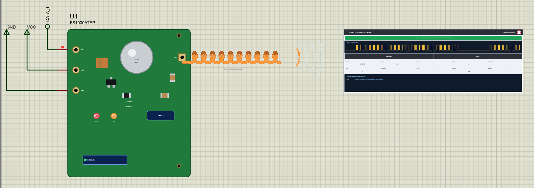
433MHz RF Module Library for Proteus V1.0: FS1000A + XY-MK-5V


Hello friends, I hope you all are doing great. Today, I am going to share the new 433MHz RF Module Library for Proteus V1.0. The FS1000A transmitter and the XY-MK-5V receiver are the cheapest wireless pair in every Arduino kit: two tiny boards that send a remote-control code across a room, switch a socket, open a gate or carry the reading of a weather sensor. They are also famous for confusing beginners, because the receiver's output is never quiet - it shows noise all the time - and because the range depends so much on the antennas. In Proteus they could not be tried at all.
Behind the parts sits our own model of how this pair behaves. The transmitter keys its 433.92 MHz carrier while DATA is HIGH, every receiver of the design hears it 20 us later, and without a carrier the receiver's DATA shows the noise of the band, as on a real module. The distance and the antennas decide what arrives: a perfect signal, a weak one that loses pulses, or nothing but noise. The unmodified rc-switch library sends and receives the codes on two Arduinos. You get Simple devices with a live STATUS panel and Advance devices with a pop-up window that draws every burst and decodes its code. The demo runs on our Arduino UNO V4.0.
NOTICE: a 433 MHz pair is easy to fake: a wire from one DATA pin to the other. We wanted more. Our receiver is noisy when nothing is sent, loses pulses when the signal is weak, hears nothing beyond its range, and two transmitters at once collide - so the rc-switch receiver on the Arduino has to find its code in the noise, exactly as on the bench. It took our team a lot of hard work. Your feedback is the fuel that keeps us going, so please tell us what you think in the comments below or in the 433 MHz RF Module board of our forum. And if our free libraries help you, you can buy us a coffee. So, let's get started with the 433MHz RF Module Library for Proteus V1.0:
What is a 433 MHz RF Module?
A 433 MHz RF module pair is a transmitter and a receiver for the licence-free 433.92 MHz band. The FS1000A (also sold as XY-FST) is the transmitter: a round SAW resonator and one transistor make the carrier. The XY-MK-5V (also MX-05V) is the receiver: a tuned input stage with a coil and a screw, and an LM358 that turns what it hears into a logic signal. There is no protocol, no address and no buffer in them - the microcontroller does all of that in software.
| FS1000A (transmitter) | XY-MK-5V (receiver) | |
|---|---|---|
| Pins | DATA, VCC, GND (+ the ANT pad) | VCC, DATA, DATA (one net), GND (+ the ANT hole) |
| Supply | 3 - 12 V: more volts, more range | 5 V |
| Frequency | 433.92 MHz | 433.92 MHz |
| Modulation | ASK / OOK: the carrier on while DATA is HIGH | DATA HIGH while it hears a carrier |
| Without a signal | no carrier | its gain turns up: DATA shows random noise |
| Antenna | a 17.3 cm wire on ANT (a quarter wave) | a 17.3 cm wire on ANT |
| Arduino library | rc-switch, RadioHead ASK ... | rc-switch, RadioHead ASK ... |
ASK / OOK: the Carrier On and Off
The transmitter is a switch for a radio carrier: DATA HIGH turns the 433.92 MHz carrier on, DATA LOW turns it off. That is called ASK, amplitude shift keying, or OOK, on-off keying. The receiver does the opposite: its DATA pin is HIGH while it hears a carrier. So every pulse the Arduino drives on the transmitter's DATA comes out of the receiver's DATA a moment later. The catch: with no carrier at all, the receiver turns its gain up until it hears noise, and DATA toggles at random. A sketch that reads the receiver with digitalRead() sees garbage; a library like rc-switch looks for a known pattern of pulses in that noise.
rc-switch Codes
The cheap 433 MHz remotes and remote sockets send short codes, and rc-switch speaks their protocols. A code of 24 bits is sent as pulses of one length, for example 350 us in protocol 1: a 0 is 1 pulse HIGH and 3 LOW, a 1 is 3 HIGH and 1 LOW, and a sync of 1 HIGH and 31 LOW ends each frame. The frame is repeated, 10 times in the demo, so the receiver has several chances. The receiver times every edge on an interrupt pin and accepts a code that comes between two sync gaps of the same length.
| Protocol | Pulse | Sync | 0 / 1 | Received by rc-switch? |
|---|---|---|---|---|
| 1 | 350 us | 1 + 31 | 1 + 3 / 3 + 1 | yes - the demo's |
| 2 | 650 us | 1 + 10 | 1 + 2 / 2 + 1 | yes - SEND 1234 16 in the demo |
| 3 | 100 us | 30 + 71 | 4 + 11 / 9 + 6 | yes |
| 4 | 380 us | 1 + 6 | 1 + 3 / 3 + 1 | no - its sync gap is too short |
| 5 | 500 us | 6 + 14 | 1 + 2 / 2 + 1 | yes, often reported as 2 |
What's New in 433MHz RF Module Library for Proteus V1.0
- Two modules: the FS1000A transmitter and the XY-MK-5V receiver, each as a Simple and an Advance device - four parts in one library.
- One shared band: every transmitter and receiver of the design are on the same virtual 433.92 MHz band; a receiver's DATA is HIGH while any transmitter it hears well enough is on, and two at once collide.
- The noise of the band: without a carrier the receiver's DATA toggles at random - pulses of 40 - 600 us HIGH with 0.2 - 4 ms LOW between them - and the noise stops at a carrier and comes back 150 ms after the last one.
- Range: the receiver's DISTANCE (1 - 150 m) and the antennas decide the signal: perfect up to 40 m with a wire on both, weaker to 100 m (pulses lost, edges moved), only noise beyond.
- The antennas: click an antenna while the simulation runs to take it off, and once more to put it back.
- The codes decoded: the panels decode rc-switch codes (protocols 1 - 5 and 7) on the transmitter's input and the receiver's output - the code, its bits, the protocol, the pulse length and how many frames were clean.
- The bursts drawn: the last burst as a trace on the STATUS panel, and on the Advance pop-up all of it with the noise around it plus its first 60 ms.
- Three test tools on the Advance devices: Codes, Pulses and Range.
- A two-node demo on our Arduino UNO V4.0 with rc-switch: the keys A - D of a remote from one monitor, the codes and the UNO's L LED on the other.
- A compact package: about 1.27 MB, without the C++ source code of the model.
Four Devices: Simple and Advance
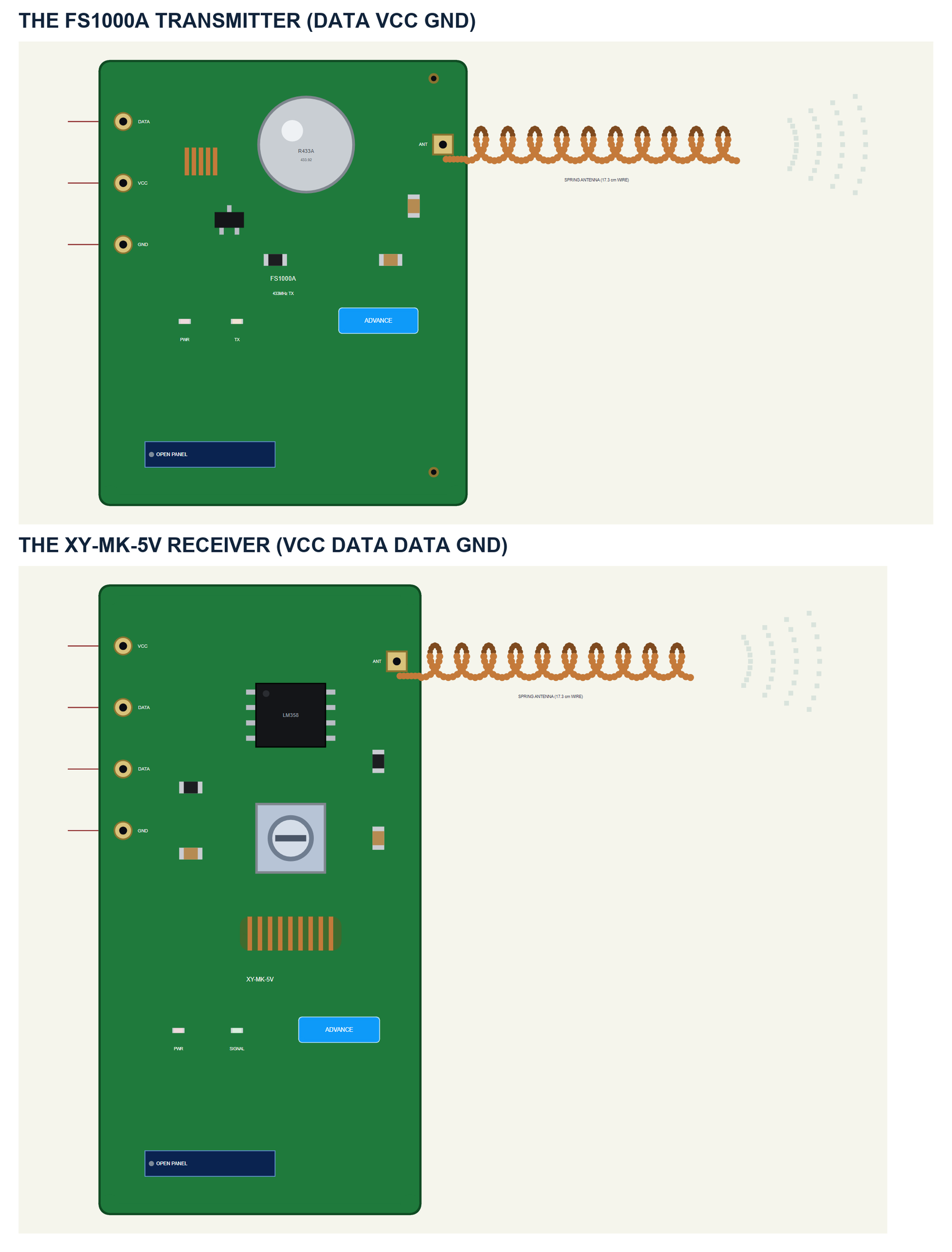
Both modules are drawn about three times their real size, the boards seen from above with the header turned to the left. The FS1000A shows its round R433A SAW resonator and its transistor; the XY-MK-5V its LM358, the tuning coil with its screw and the green coil. A spring antenna is soldered to each ANT pad, and the pins are in the real order: DATA VCC GND on the transmitter, VCC DATA DATA GND on the receiver. The SIMPLE / ADVANCE badge, the PWR and TX / SIGNAL LEDs, the panel button and the radio waves beside the antenna's tip are TEP additions: the waves go out while the transmitter sends and come in while the receiver hears a carrier.
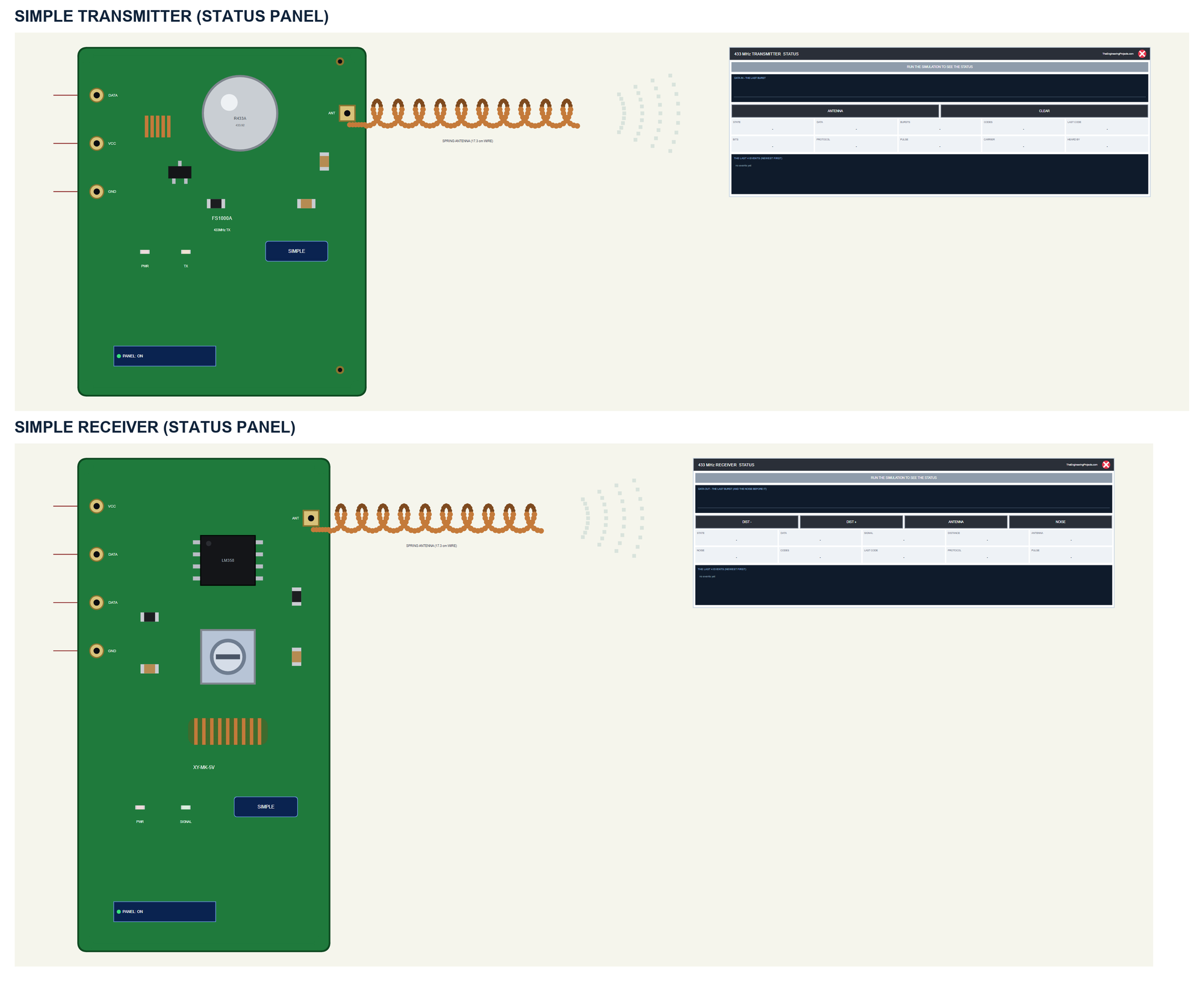
| Simple | Advance | |
|---|---|---|
| Transmitter | FS1000ATEP | FS1000AADVTEP |
| Receiver | XYMK5VTEP | XYMK5VADVTEP |
| On the schematic | The module, its antenna and the STATUS panel | The module and its antenna |
| The antenna | Click it, or ANTENNA on the panel | Click it, or ANTENNA in the pop-up |
| The receiver's range | DIST - and DIST + on the panel | DIST - and DIST + on the pop-up's toolbar |
| Status | Banner, the last burst, 10 readouts, the last 4 events | A pop-up: Air, Event log, Tests |
Download 433MHz RF Module Library for Proteus
Click the button below to download 433MHz-RF-Module-Library-for-Proteus-v1.0.zip (about 1.27 MB, without the C++ source code of the model):
433MHz RF Module Library for Proteus V1.0- README.txt: the devices, installation, the demo, wiring, the test tools, the properties and real hardware.
- Proteus Library Files:
TEPRF433.LIBandArduinoV4TEP.LIBfrom our Arduino Library for Proteus V4.0. - Proteus Model Files:
TEPRF433.DLLandTEPARDUINO.DLL. - Proteus Simulation:
RF433-FS1000A-XY-MK-5V-ArduinoUnoV4.pdsprj,RF433_TX.hex,RF433_RX.hexand copies of the two DLLs. - Arduino Code:
RF433_TX.inoandRF433_RX.ino- they need the rc-switch library (not included; install it with the Library Manager).
No Proteus yet? Read How to Download and Install Proteus 7 and 8. New to libraries? Follow How to Install a New Library in Proteus.
How to Install 433MHz RF Module Library for Proteus
- Close Proteus and extract the whole zip file, for example to your Desktop.
- Copy the two files from Proteus Library Files into the LIBRARY folder of Proteus (usually
C:\Program Files (x86)\Labcenter Electronics\Proteus 8 Professional\LIBRARY). - Copy
TEPRF433.DLLandTEPARDUINO.DLLfrom Proteus Model Files into the MODELS folder. - Delete
TEPRF433.IDXfrom the LIBRARY folder if it is there. - Start Proteus, press P and search for 433.
Tip: keep the Proteus Simulation folder together, because the project needs its two .hex files and the DLLs beside it. The library is tested in Proteus 8.5; Proteus 7 is not supported.
The 433 MHz Parts in Proteus
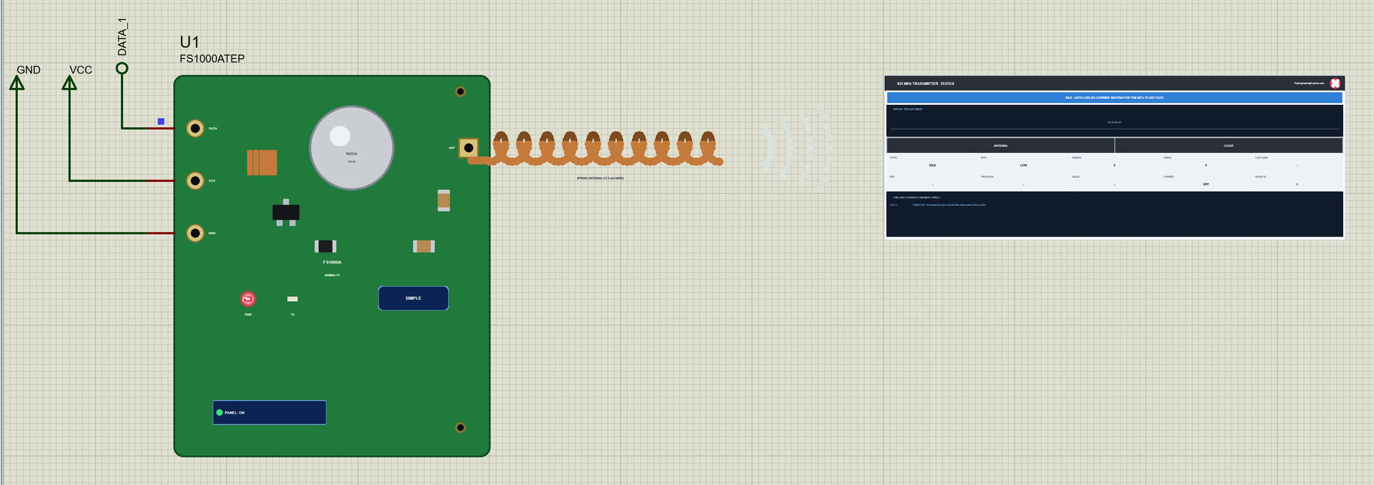
The Simple devices add the STATUS panel beside the antenna's waves. Its banner says what the module is doing: green while it sends or hears a code, blue when it is idle or listening, amber for a weak signal or DATA stuck HIGH, red for no power. Below it is the last burst as a trace, the actions, ten readouts and the last four events. The transmitter's readouts are the state, DATA, the bursts and codes sent, the last code with its bits, protocol and pulse length, the carrier and how many receivers hear it; its actions are ANTENNA and CLEAR. The receiver shows the signal, the distance, the antenna and the noise, and its actions are DIST -, DIST +, ANTENNA and NOISE. The red X closes the STATUS panel, and the PANEL button on the board opens it again.
The Advance devices keep the schematic clean: only the module and its antenna. The live data opens in a pop-up window at Run, and the OPEN PANEL button on the board brings the window back:
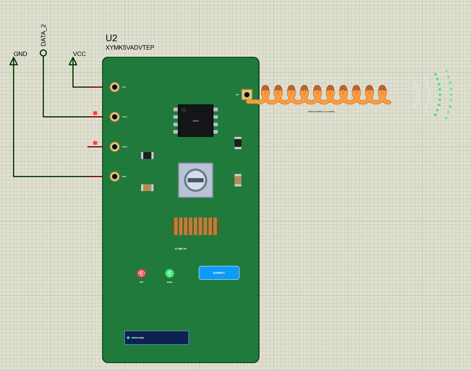
The properties set the start: ANTENNA on both (WIRE, the 17.3 cm wire, or NONE), and on the receiver DISTANCE (1, 3, 10, 20, 40, 60, 80, 100 or 150 m from the transmitters) and NOISE (ON as on a real module, or OFF for a clean trace). The Simple devices add PANEL (open or closed). Every run starts again from the properties.
The Demo Circuit
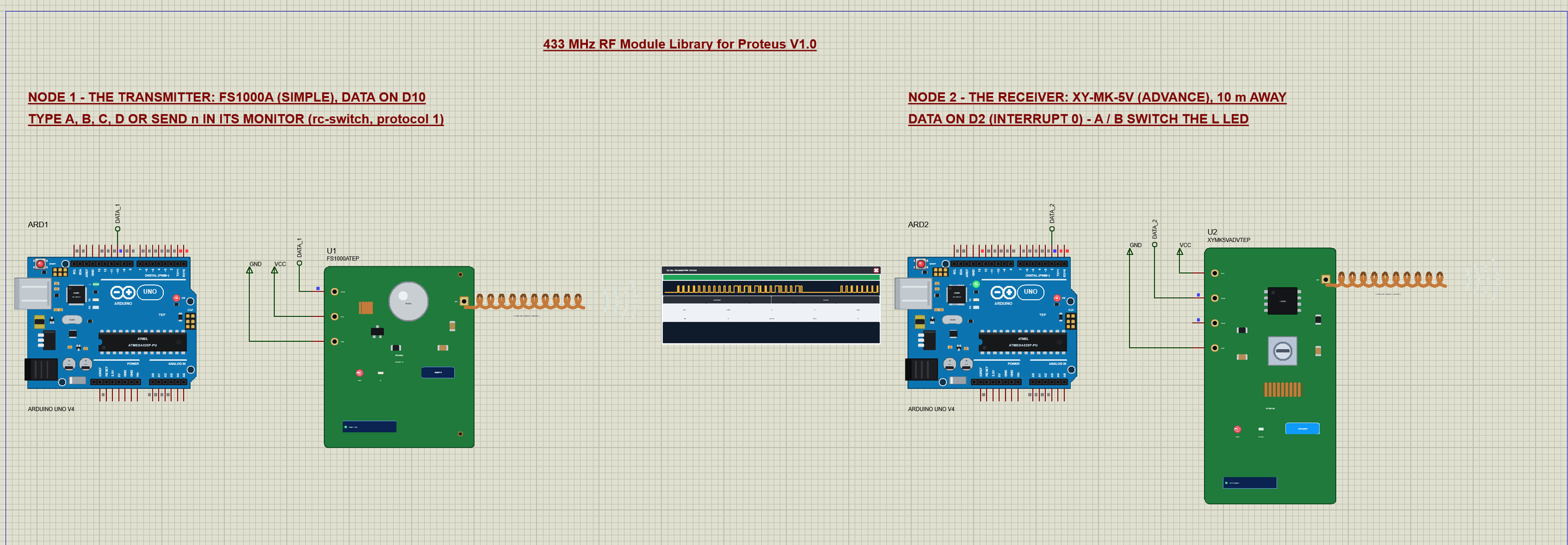
The demo project has two nodes, each an Arduino UNO V4.0 from our Arduino UNO Library for Proteus V4.0. Node 1 is the transmitter: ARD1 runs RF433_TX.hex and keys the FS1000A on D10. Node 2 is the receiver, 10 m away: ARD2 runs RF433_RX.hex and reads the XY-MK-5V on D2. The transmitter is a Simple part, to watch it on the schematic; the receiver an Advance part, to watch it in the pop-up.
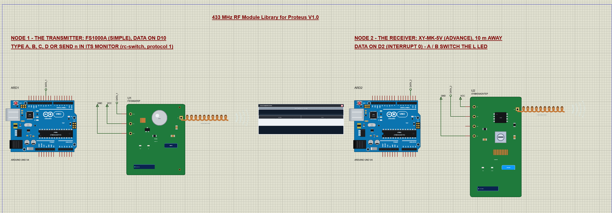
Wiring
| Module pin | Arduino UNO (the demo) | Notes |
|---|---|---|
| FS1000A DATA | D10 | any digital pin: rc-switch's enableTransmit(pin) |
| FS1000A VCC | 5V | a real FS1000A takes 3 - 12 V |
| XY-MK-5V DATA | D2 | interrupt 0 (D3 = interrupt 1) - either DATA pin |
| XY-MK-5V VCC | 5V | the XY-MK-5V wants 5 V |
| GND | GND | both modules |
In the demo VCC and GND go to power terminals and DATA to labels (DATA_1 and DATA_2) at the UNO's header; the receiver's second DATA pin stays open. The serial monitors need no wires at all, because they are built into the UNO V4.0. In Proteus the two nodes need no connection either: the radio link between them is the band inside the model.
The Arduino Code
Both demo sketches use the rc-switch library 2.6.4 by sui77 and its contributors (LGPL licence) - install it with the Library Manager to rebuild them. New to Arduino? Start with Arduino Tutorial for Beginners and Introduction to Arduino UNO.
The Transmitter: RF433_TX
The transmitter sketch knows the four codes of a 4-key remote:
RCSwitch radio;
const byte TX_PIN = 10;                          // the FS1000A's DATA
const unsigned long CODES[4] = {5393, 5396, 5521, 5524};   // the keys A - D: channel 1 ON / OFF, channel 2 ON / OFF
char line[24];
In setup() it tells rc-switch where DATA is, which protocol to use and how many times to send each code:
  radio.enableTransmit(TX_PIN);
  radio.setProtocol(1);                          // 350 us pulses: '0' = 1 + 3, '1' = 3 + 1, sync = 1 + 31
  radio.setRepeatTransmit(10);
send() prints the code, sends it and prints how long that took. radio.send() returns only when all ten frames are on the air, so the time is the length of the whole burst:
void send(unsigned long code, unsigned int bits) {
  stamp();
  Serial.print(F("sending "));
  Serial.print(code);
  Serial.print(F(" ("));
  Serial.print(bits);
  Serial.println(F(" bits)"));
  unsigned long t0 = millis();
  radio.send(code, bits);                        // the code, then the sync - as many times as setRepeatTransmit says
  stamp();
  Serial.print(F("sent in "));
  Serial.print(millis() - t0);
  Serial.println(F(" ms"));
}
The keys of the monitor pick a code, and the other commands change rc-switch's settings:
  if (!c[1] && c[0] >= 'A' && c[0] <= 'D') send(CODES[c[0] - 'A'], 24);
  else if (!strncmp(c, "SEND", 4)) send(n, m);
  else if (!strncmp(c, "PROTOCOL", 8)) { radio.setProtocol(n); Serial.print(F("protocol ")); Serial.println(n); }
PULSE n, REPEAT n and HELP work the same way. It needs 8,362 bytes of flash and 455 bytes of RAM.
The Receiver: RF433_RX
The receiver sketch turns rc-switch's receiver on for interrupt 0 - pin D2 - so every edge of DATA is timed, the noise included:
radio.enableReceive(0); // interrupt 0 = D2: every edge of DATA is timedA remote sends its code ten times, and rc-switch may report it more than once. The loop prints a code only once per press: the same code again within 300 ms is counted, not printed:
void loop() {
  if (!radio.available()) return;
  unsigned long code = radio.getReceivedValue();
  unsigned long now = millis();
  if (code == lastCode && now - lastAt < 300) {  // the same press, repeated
    lastAt = now;
    repeats++;
    radio.resetAvailable();
    return;
  }
  lastCode = code;
  lastAt = now;
  repeats = 0;
Then it prints the code with its bit length, protocol and pulse length:
    Serial.print(F("received "));
    Serial.print(code);
    Serial.print(F(" / "));
    Serial.print(radio.getReceivedBitlength());
    Serial.print(F(" bit / protocol "));
    Serial.print(radio.getReceivedProtocol());
    Serial.print(F(" / pulse "));
    Serial.print(radio.getReceivedDelay());
    Serial.println(F(" us"));
The keys A - D are a 2-channel remote switch: A and B switch channel 1 - the UNO's L LED - on and off, C and D channel 2:
    for (byte k = 0; k < 4; k++) {
      if (code != CODES[k]) continue;
      bool on = k % 2 == 0;                      // A, C = ON; B, D = OFF
      if (k < 2) digitalWrite(LED_BUILTIN, on);
      stamp();
      Serial.print(F("key "));
      Serial.print(char('A' + k));
      Serial.print(F(": channel "));
      Serial.print(k / 2 + 1);
      Serial.println(on ? F(" ON") : F(" OFF"));
    }
It needs 6,840 bytes of flash and 406 bytes of RAM. The HEX files are in the package, so you do not need the Arduino IDE to run the demo. To change a sketch, open it in the Arduino IDE and export the compiled binary, as in How to get the HEX file from Arduino.
The Start: Listening to the Noise
At Run, U2 opens its own window, 433 MHz Receiver XY-MK-5V, with the look of our TEP Serial Monitor Advance for Proteus. It has three tabs, Air, Event log and Tests, plus Settings and Help behind the gear and question mark icons. Before any code is sent, the receiver already has something on DATA:
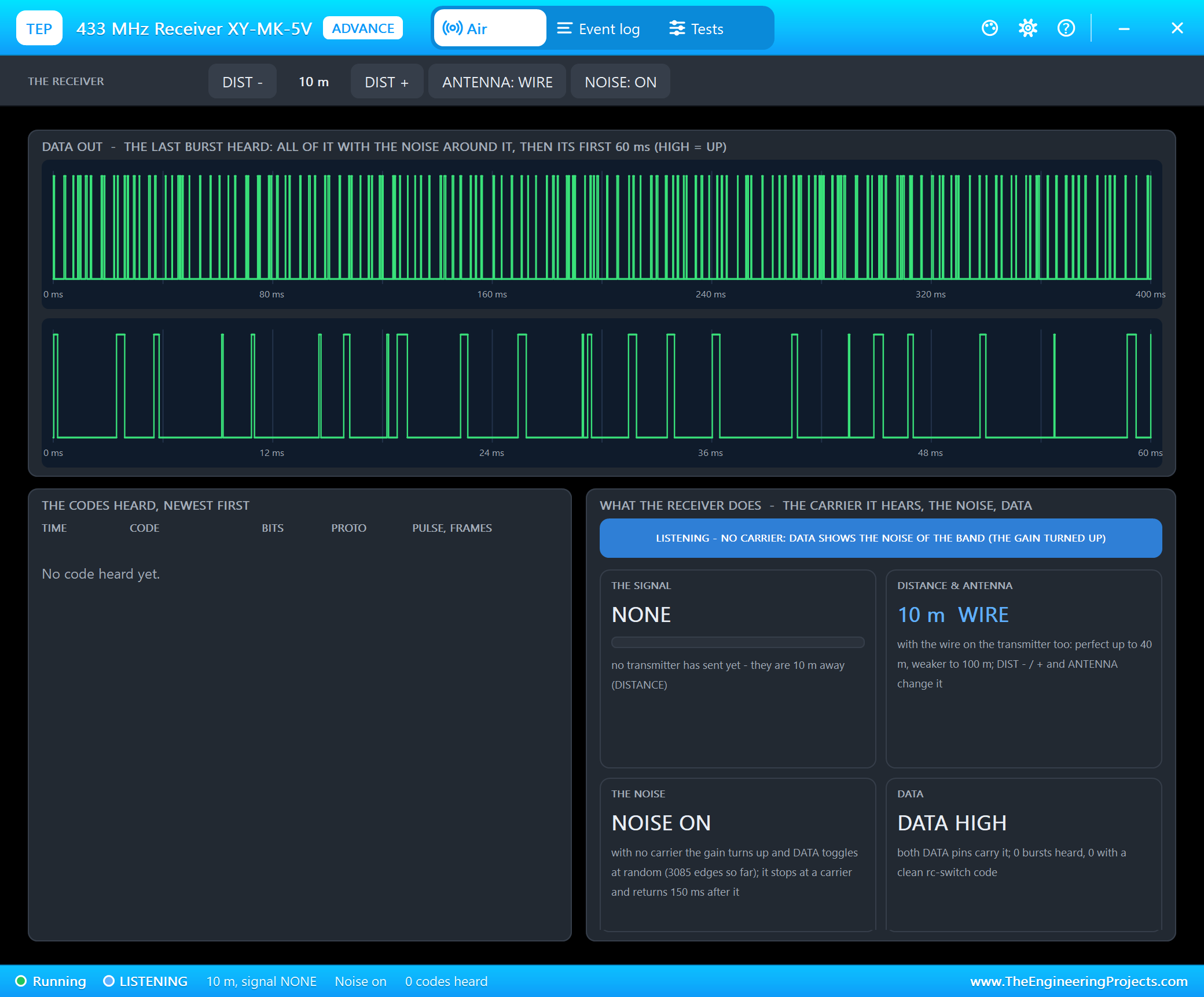
This is the most important thing to know about the XY-MK-5V: with no carrier its automatic gain turns up until the noise toggles DATA - short pulses at random. The top trace is 400 ms of it, the lower one the first 60 ms. rc-switch on ARD2 times all these edges and finds no code in them, so ARD2's monitor only shows the start of the sketch.
Sending a Code: A, B, C, D
We typed A in ARD1's monitor. The FS1000A sent 5393 ten times, and U2 heard it:
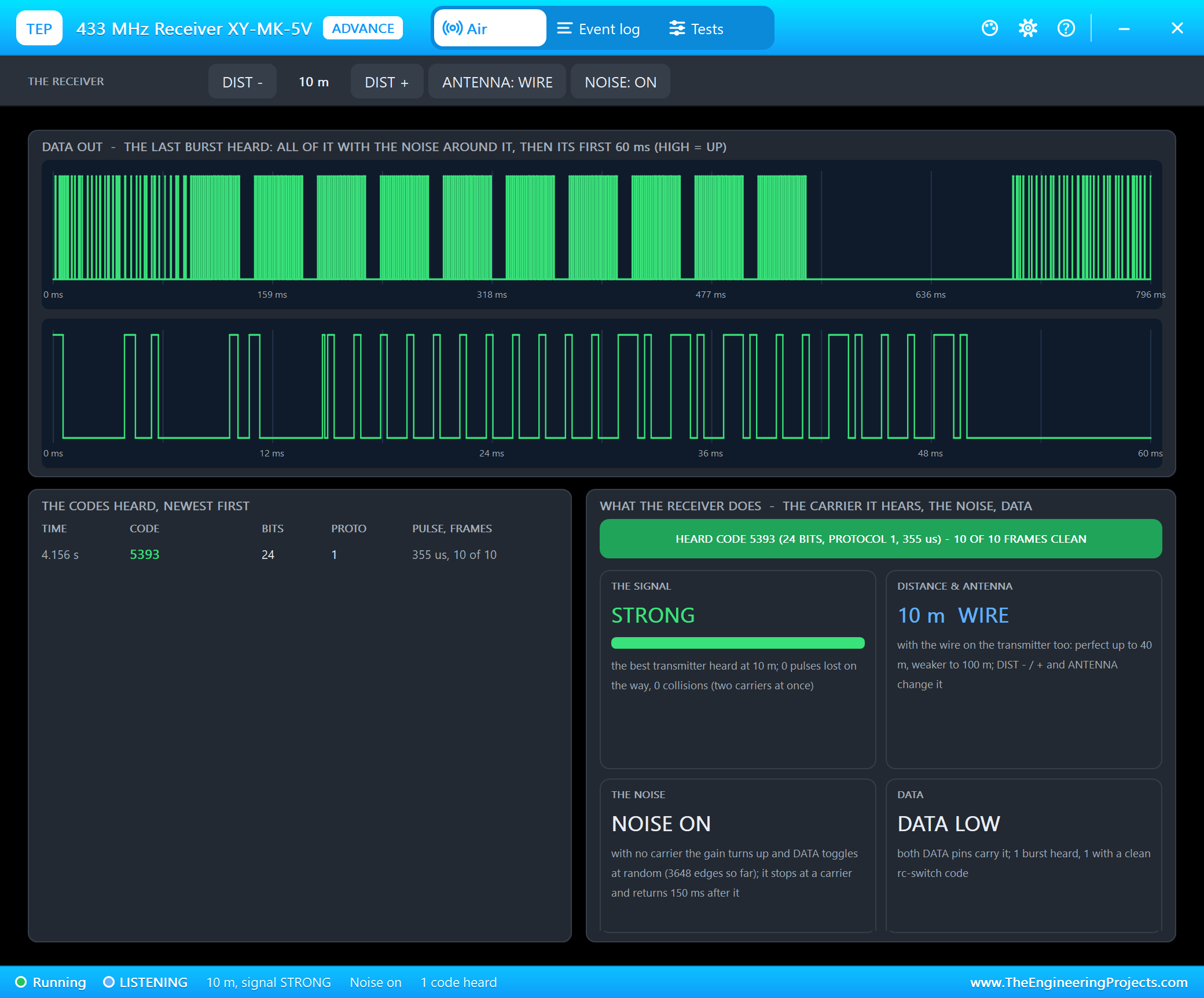
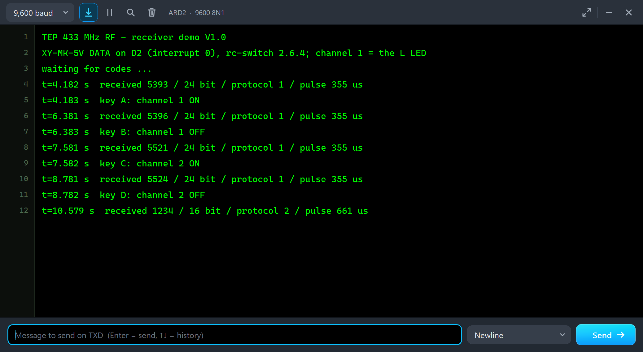
Read the top trace from the left: the noise, then the ten frames of the burst as ten green blocks, then 150 ms of quiet - the receiver's gain is still turned down after the carrier - and then the noise again. The lower trace is the first 60 ms: the noise stops at the first pulse of the carrier, and the data bits of 5393 follow, short and long pulses, ending with the sync. ARD2 printed the code and switched its L LED on:
TEP 433 MHz RF - receiver demo V1.0
XY-MK-5V DATA on D2 (interrupt 0), rc-switch 2.6.4; channel 1 = the L LED
waiting for codes ...
t=4.182 s  received 5393 / 24 bit / protocol 1 / pulse 355 us
t=4.183 s  key A: channel 1 ON
t=6.381 s  received 5396 / 24 bit / protocol 1 / pulse 355 us
t=6.383 s  key B: channel 1 OFF
t=7.581 s  received 5521 / 24 bit / protocol 1 / pulse 355 us
t=7.582 s  key C: channel 2 ON
t=8.781 s  received 5524 / 24 bit / protocol 1 / pulse 355 us
t=8.782 s  key D: channel 2 OFF
t=10.579 s  received 1234 / 16 bit / protocol 2 / pulse 661 us
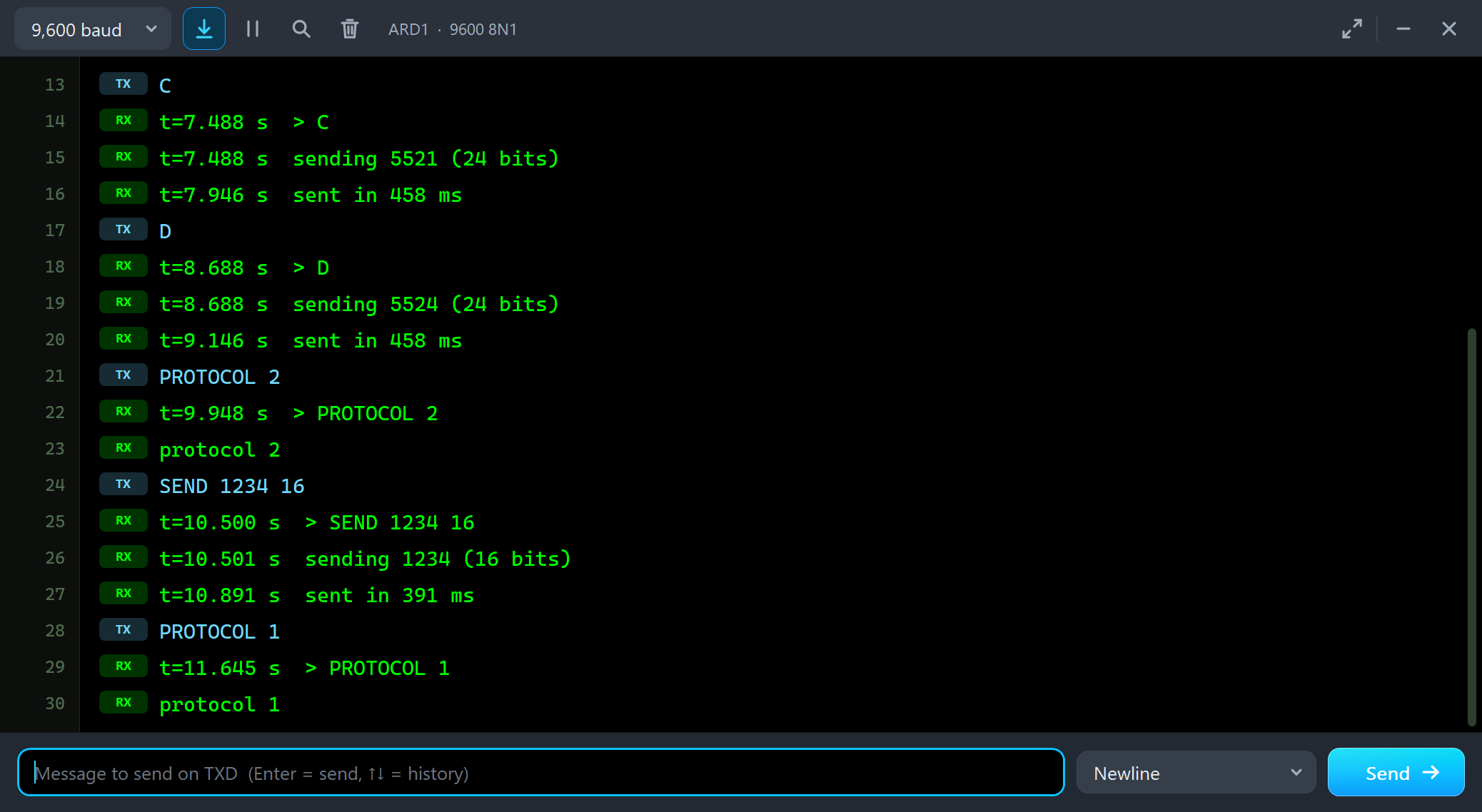
Note the pulse: 355 us, not the 350 us of protocol 1. That is no error of the receiver - the UNO needs a few microseconds for every digitalWrite() besides delayMicroseconds(), so the real pulses on the air are 355 us long, and the panels measure the same. A code was printed about 90 ms after its key, while the rest of the ten frames was still on the air: rc-switch needs only two frames. On ARD1, every code took 458 ms:
C
t=7.488 s  > C
t=7.488 s  sending 5521 (24 bits)
t=7.946 s  sent in 458 ms
D
t=8.688 s  > D
t=8.688 s  sending 5524 (24 bits)
t=9.146 s  sent in 458 ms
PROTOCOL 2
t=9.948 s  > PROTOCOL 2
protocol 2
SEND 1234 16
t=10.500 s  > SEND 1234 16
t=10.501 s  sending 1234 (16 bits)
t=10.891 s  sent in 391 ms
PROTOCOL 1
t=11.645 s  > PROTOCOL 1
protocol 1
Another Protocol: SEND 1234 16
Then PROTOCOL 2 and SEND 1234 16 - a 16-bit code with 650 us pulses:
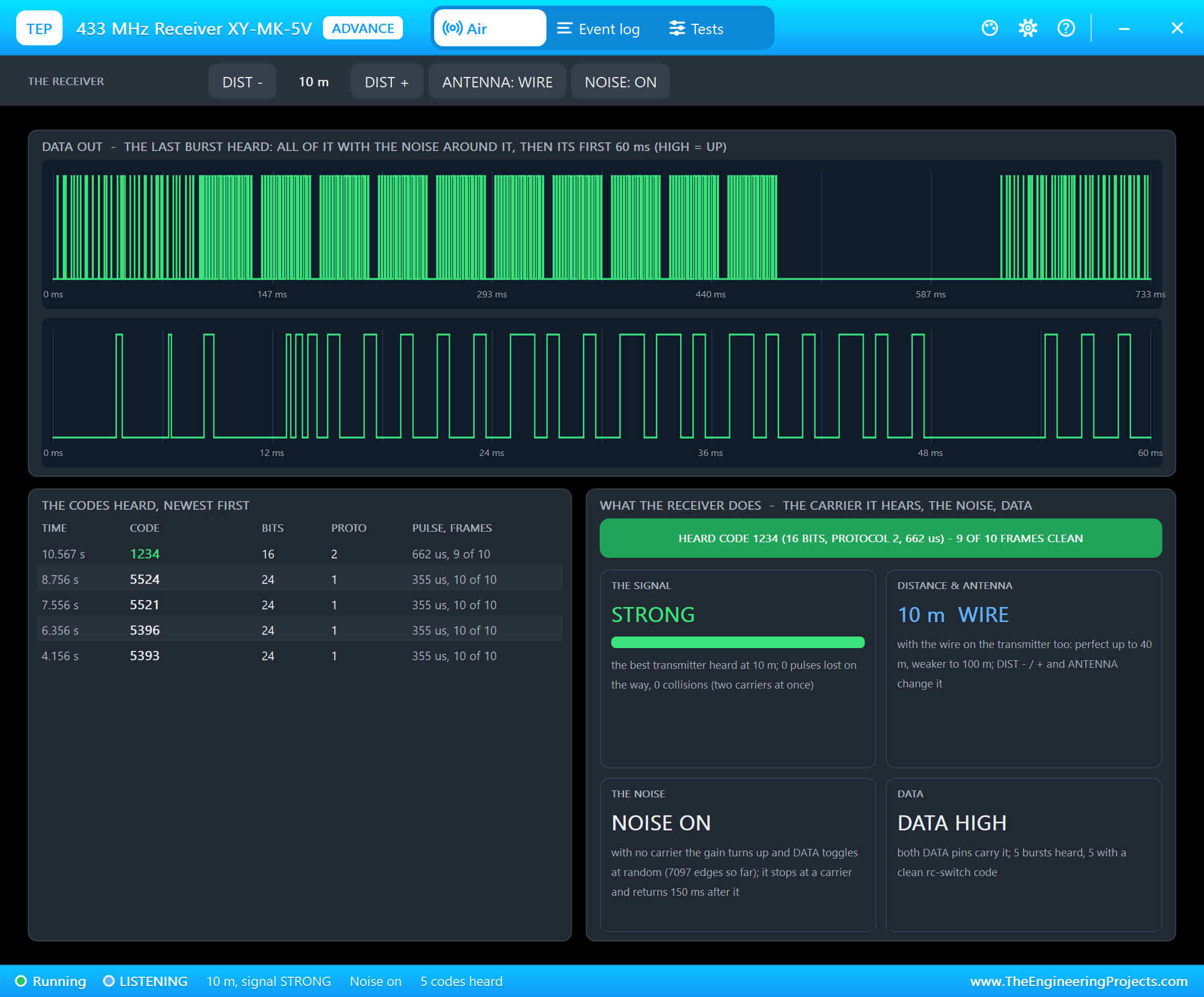
The receiver needs no setting for that: rc-switch's receiver tries the protocols in order and takes the first one that fits, within 60 %. It printed "protocol 2 / pulse 661 us". The panel measured 662 us - two decoders, each rounding its own way.
The Range: 80 m, 150 m and No Antenna
Now the part that you cannot see on a real bench without a long walk. With DIST + on the pop-up's toolbar we moved the receiver to 80 m and sent A, B and A again:
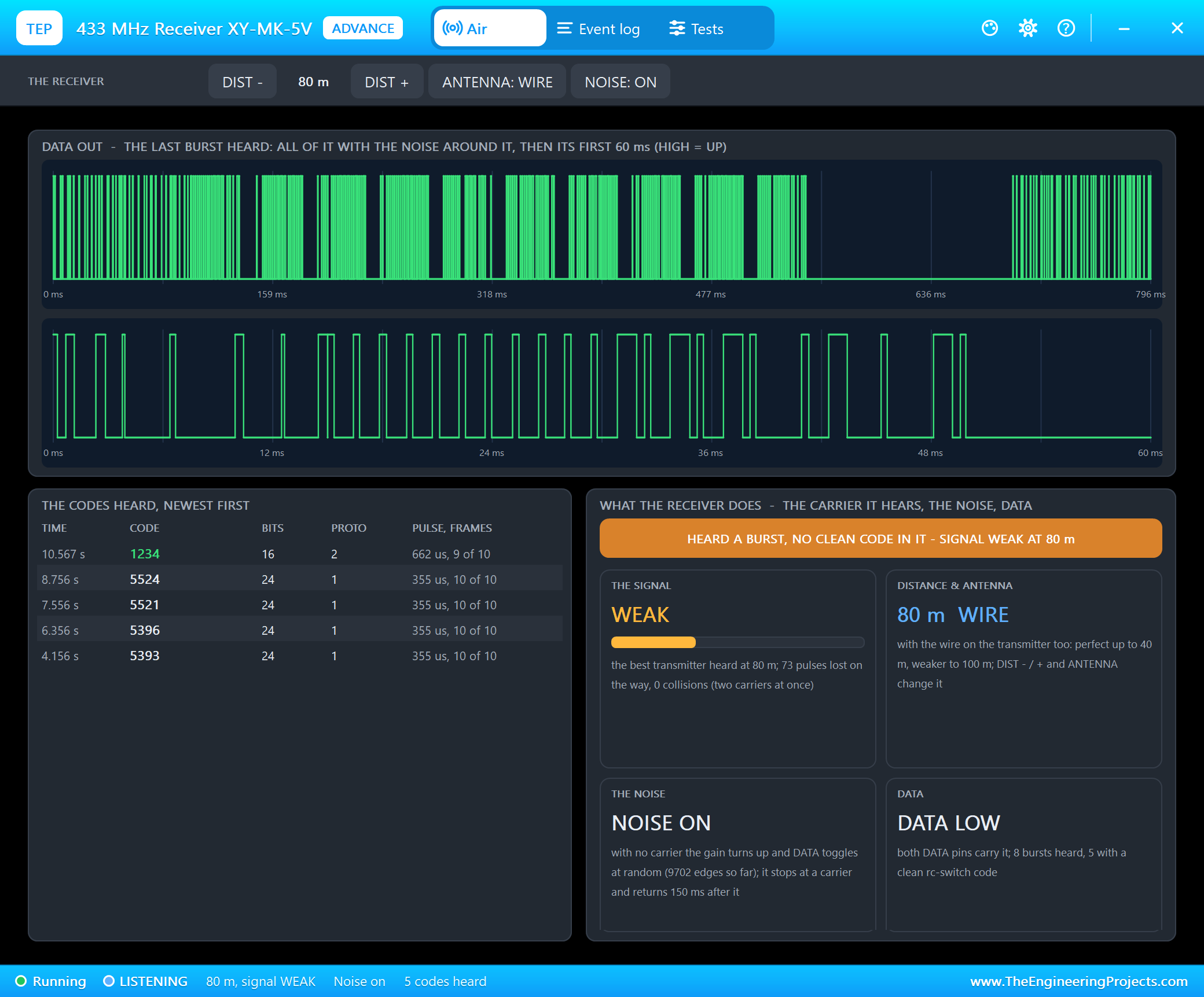
With a wire on both antennas the pair is perfect up to 40 m and gets weaker up to 100 m. A weak signal loses pulses on the way and moves edges, and a frame with one pulse missing is no longer a code. Here 73 pulses were lost in three bursts, no frame came through clean, and ARD2 printed nothing - on a real pair this is the "works on the desk, not in the garden" moment. At 150 m the receiver hears nothing at all:
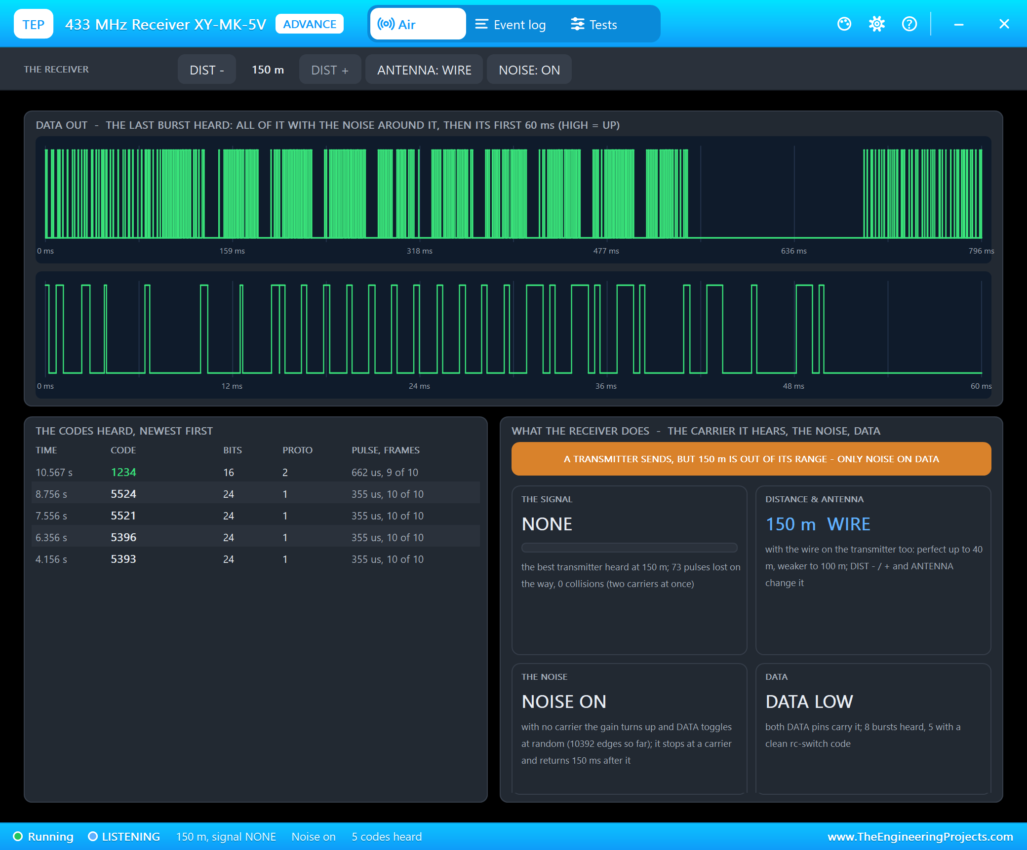
Back at 10 m, we took the receiver's antenna off with ANTENNA and sent A once more:
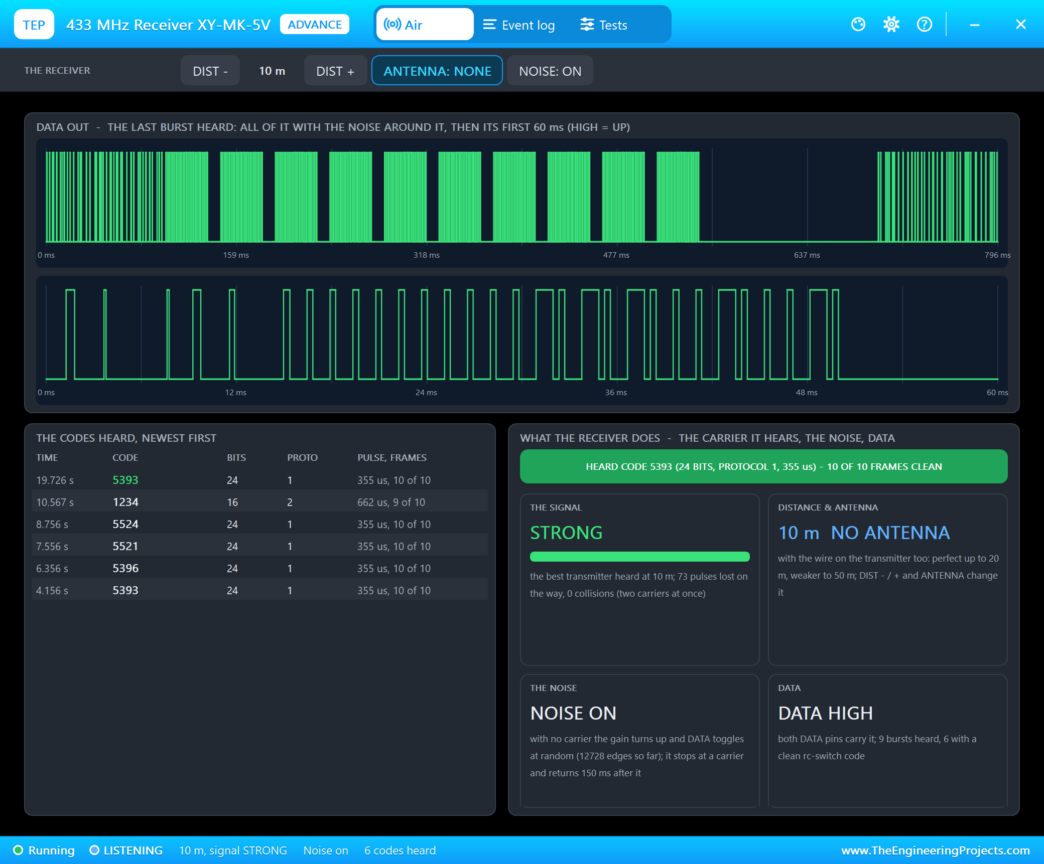
Without its antenna the receiver has half the range - perfect up to 20 m - so 10 m is still fine. Without the transmitter's antenna the range drops to a quarter, and with no antenna at all to 5 m. The Range tool lists all four.
NOISE OFF and a Code from the Past
For a clean picture of a burst, NOISE on the toolbar turns the noise off - DATA stays LOW without a carrier, which no real module does. We sent B:
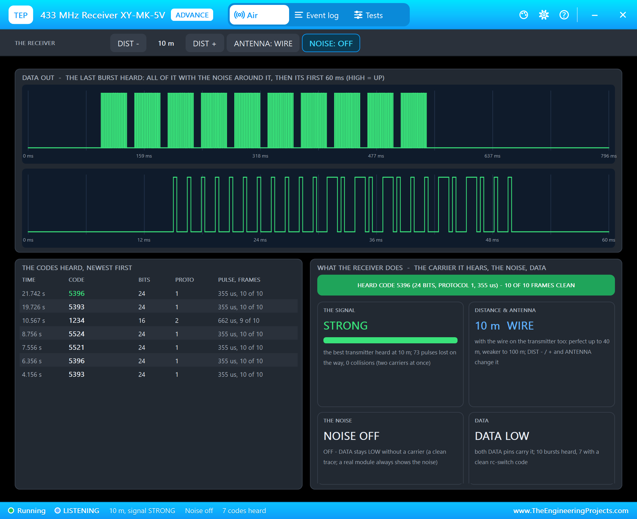
Now every frame stands alone: 24 bits and the sync, ten times. Then we turned the noise back on, and ARD2 printed something nobody had sent:
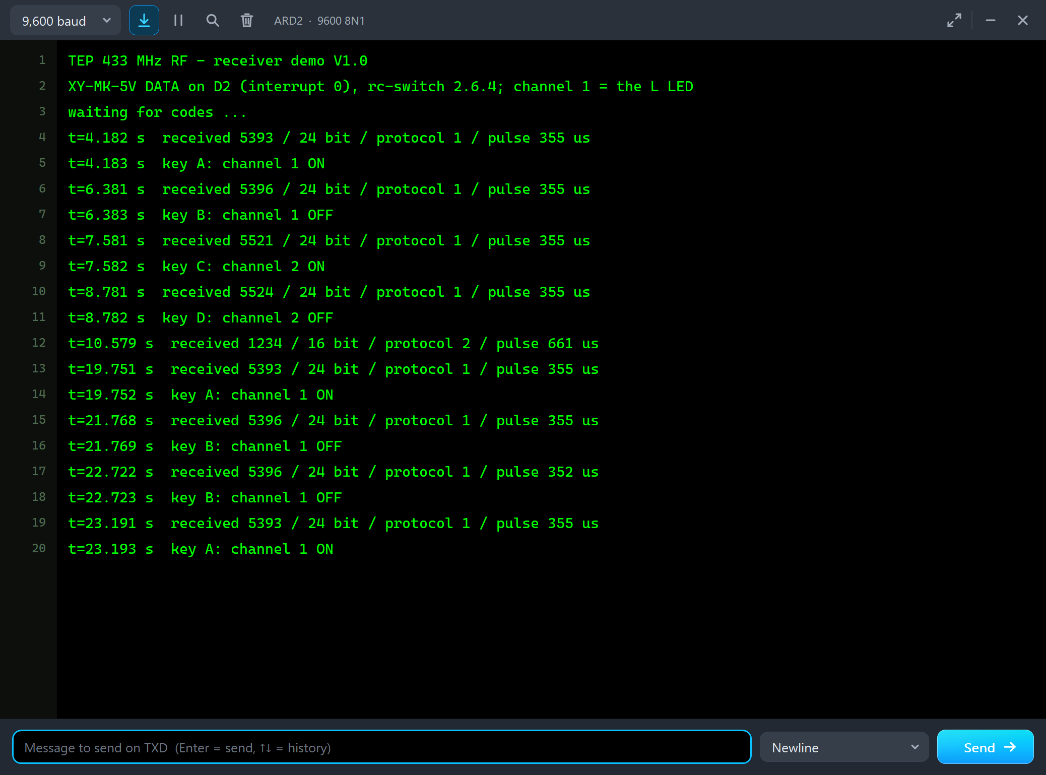
t=19.751 s  received 5393 / 24 bit / protocol 1 / pulse 355 us
t=19.752 s  key A: channel 1 ON
t=21.768 s  received 5396 / 24 bit / protocol 1 / pulse 355 us
t=21.769 s  key B: channel 1 OFF
t=22.722 s  received 5396 / 24 bit / protocol 1 / pulse 352 us
t=22.723 s  key B: channel 1 OFF
t=23.191 s  received 5393 / 24 bit / protocol 1 / pulse 355 us
t=23.193 s  key A: channel 1 ON
The second 5396, with a pulse of 352 us, came when the noise returned, about a second after B was sent. On the UNO rc-switch keeps the time between two edges in 16 bits - at most 65 ms - so the 0.6 s of silence after the burst wrapped around and came out as 10.9 ms: one more sync gap. rc-switch took it as the end of a frame and decoded the last frame of B a second time, with the pulse length from that gap, 10.9 ms / 31 = 352 us. With the noise on, as on every real module, the silence after a burst is always about 150 ms, and that never looks like a sync gap of protocol 1. It is a good reason to leave NOISE on and to treat a code as a key press only once, as the demo does.
The Test Tools
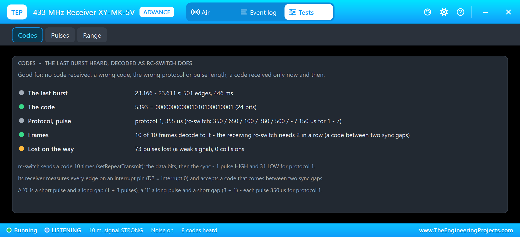
The Codes tool decodes the last burst as rc-switch does: the code in decimal and binary, the protocol and its pulse length next to rc-switch's own, how many frames decode to it and how many pulses were lost on the way. Good for no code received, a wrong code or protocol, or a code received only now and then.
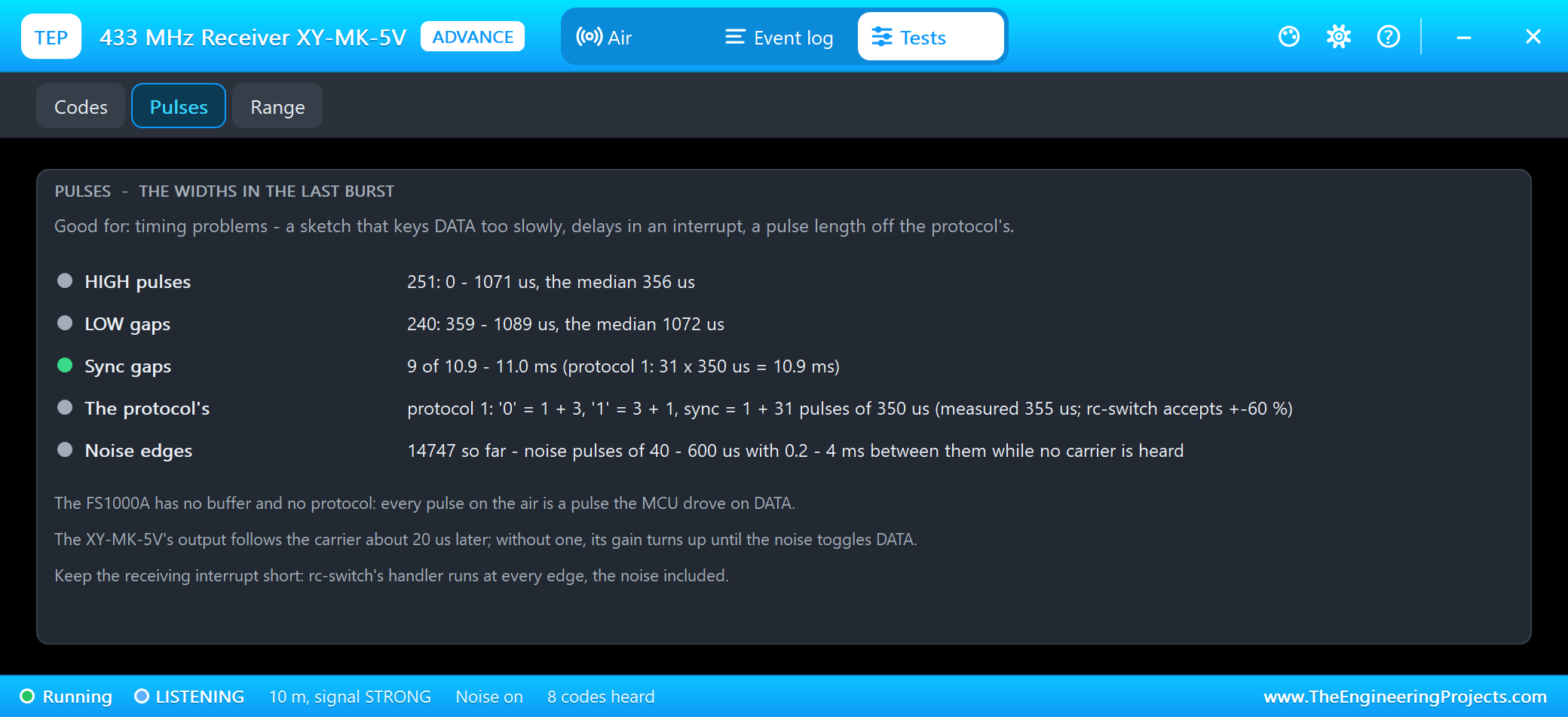
The Pulses tool measures the widths in the last burst: the HIGH pulses, the LOW gaps and the sync gaps, with the shortest, the longest and the median, next to the shapes of the protocol. Good for timing problems - a sketch that keys DATA too slowly, delays in an interrupt or a pulse length off the protocol's.
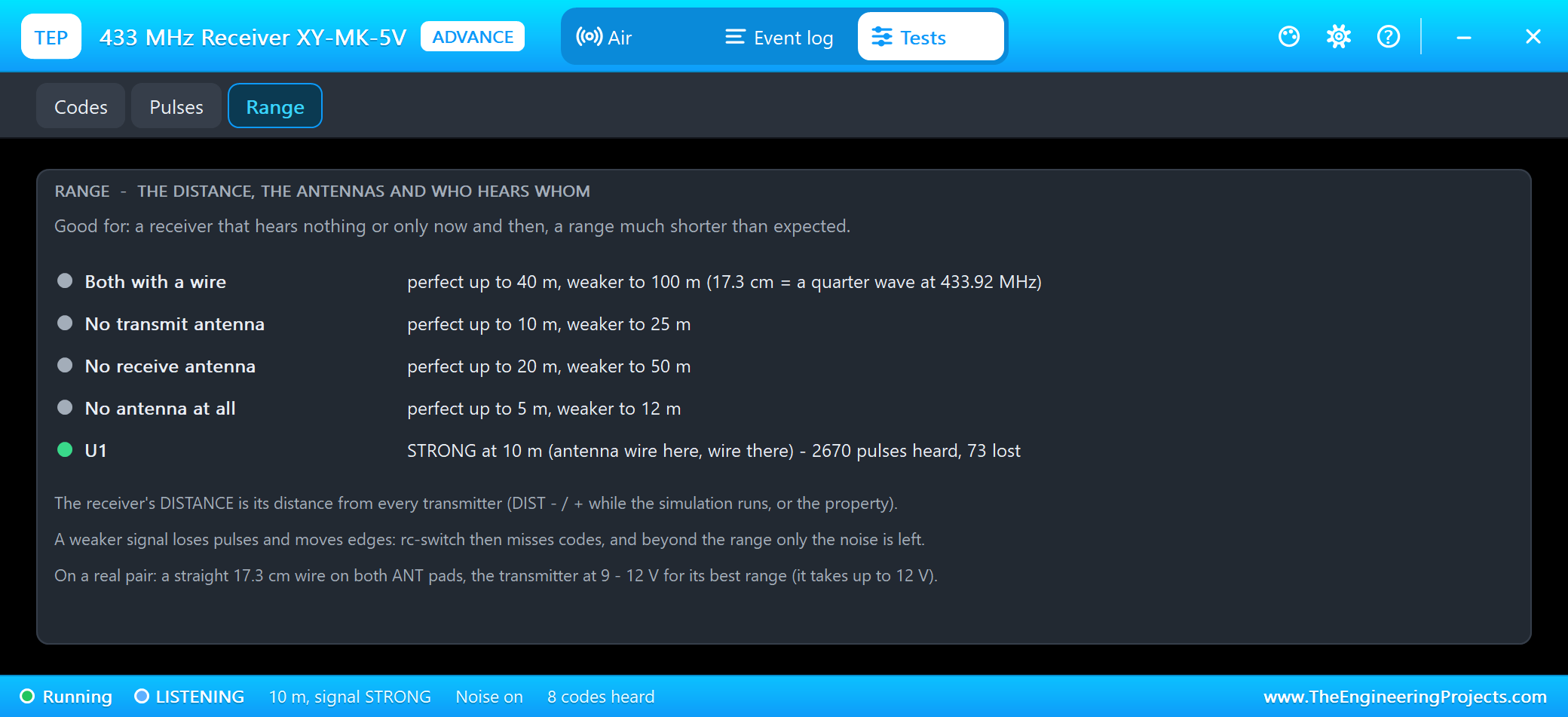
The Range tool shows the range for each antenna combination and every link of the design: here U1, heard STRONG at 10 m, 2670 pulses heard and 73 lost. Good for a receiver that hears nothing or only now and then.
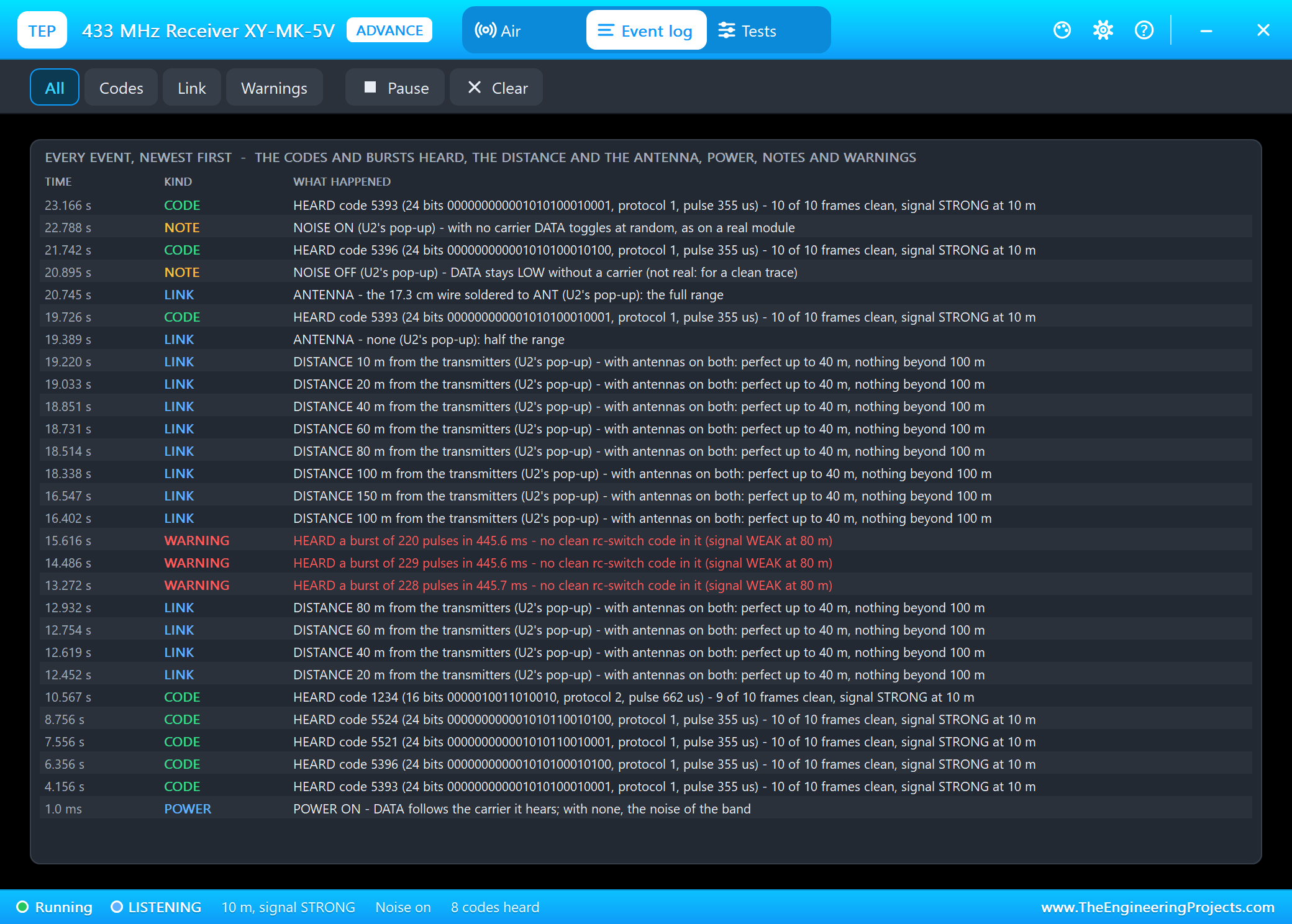
The Event log lists everything that happened, newest first: the codes and bursts, the distance and the antennas, power, notes and warnings. Filter it, pause it, or clear it.
The Transmitter with the Mouse
Back to node 1, the Simple transmitter. We typed A in ARD1's monitor and watched U1 while it sent:
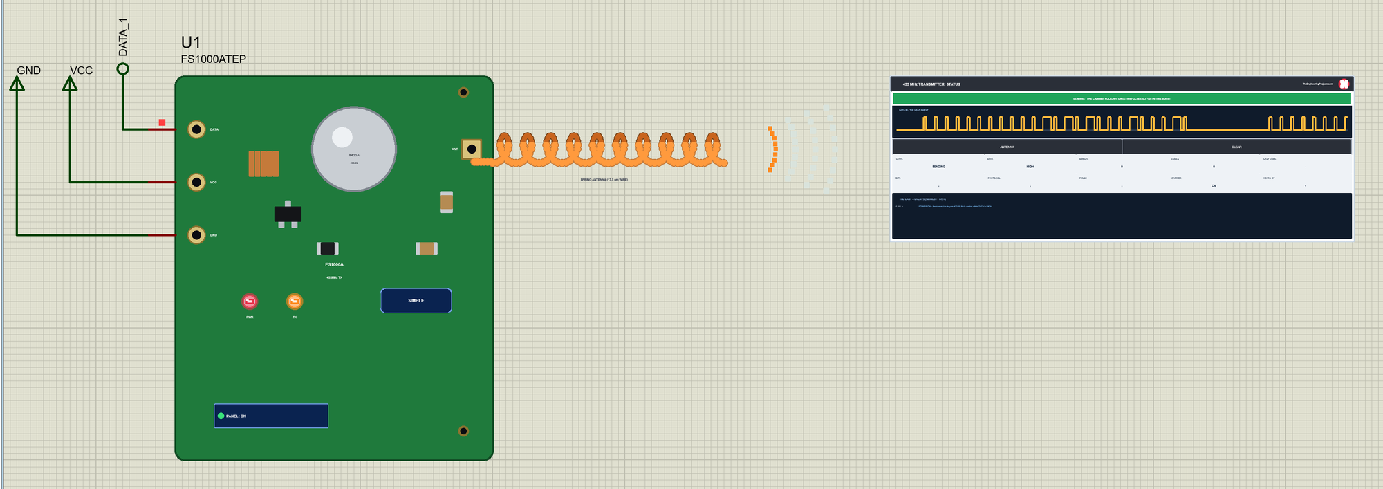
While the carrier is on, the antenna glows, the TX LED is lit and the waves go out. The panel draws DATA as the transmitter gets it and counts the pulses of the burst. Then we clicked ANTENNA on the panel and sent B:
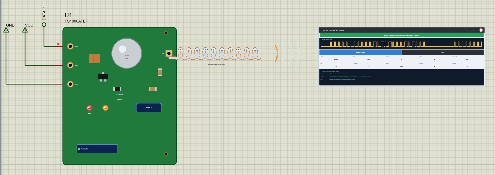
Only a light outline of the antenna is left, and the range drops to a quarter - still enough at 10 m, so the receiver heard B. A click on the antenna itself put it back. The close-up of the panel shows the whole story in its last four events:
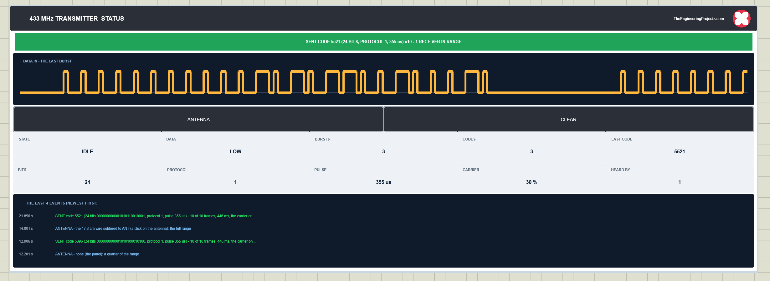
The trace is the last burst on DATA: the data bits of a frame, the long sync gap, and the next frame. The readouts count three bursts and three codes, the carrier was on for 30 % of the burst, and one receiver heard it. ARD1's monitor shows the start of the sketch and the two keys:
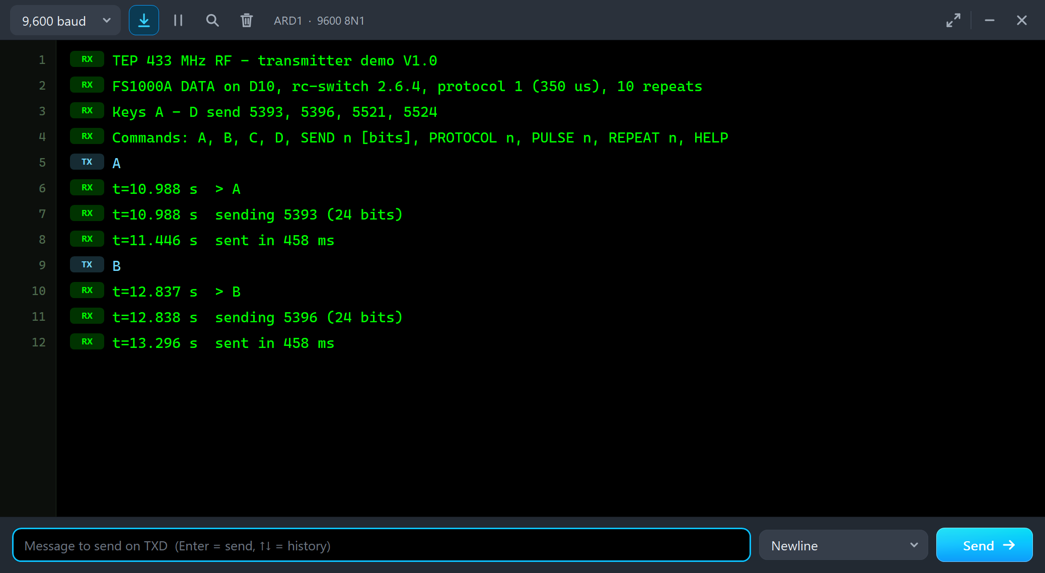
TEP 433 MHz RF - transmitter demo V1.0
FS1000A DATA on D10, rc-switch 2.6.4, protocol 1 (350 us), 10 repeats
Keys A - D send 5393, 5396, 5521, 5524
Commands: A, B, C, D, SEND n [bits], PROTOCOL n, PULSE n, REPEAT n, HELP
and then:
A
t=10.988 s  > A
t=10.988 s  sending 5393 (24 bits)
t=11.446 s  sent in 458 ms
B
t=12.837 s  > B
t=12.838 s  sending 5396 (24 bits)
t=13.296 s  sent in 458 ms
Every click on the panel and on the antenna was read back from the model on the first try.
The Simulation Log
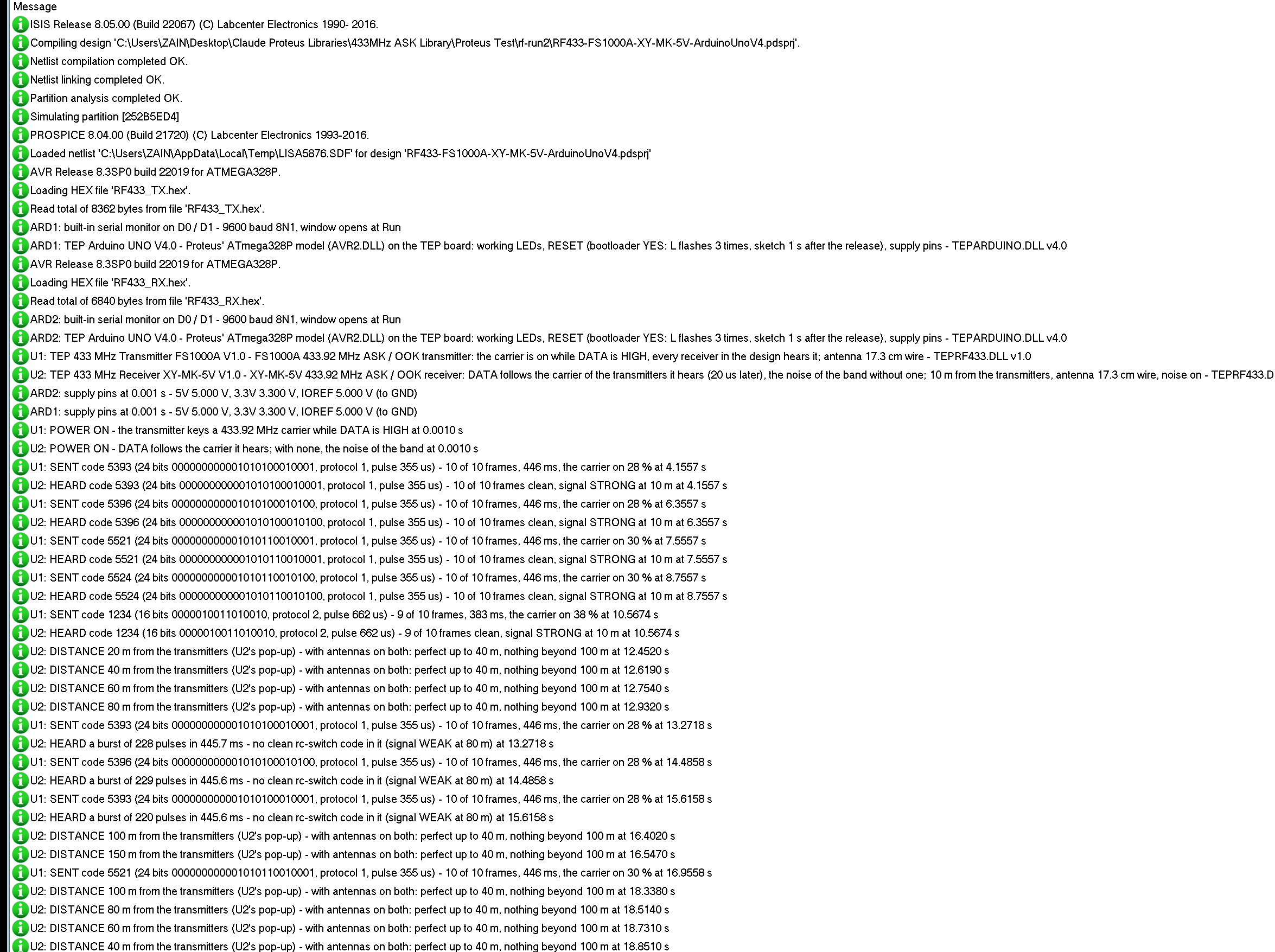
The parts also write to the simulation log of Proteus, with the exact simulation time. These lines show the power-on, the first code, protocol 2, a weak burst at 80 m and a code sent at 150 m that no receiver heard:
U1: POWER ON - the transmitter keys a 433.92 MHz carrier while DATA is HIGH at 0.0010 s
U2: POWER ON - DATA follows the carrier it hears; with none, the noise of the band at 0.0010 s
U1: SENT code 5393 (24 bits 000000000001010100010001, protocol 1, pulse 355 us) - 10 of 10 frames, 446 ms, the carrier on 28 % at 4.1557 s
U2: HEARD code 5393 (24 bits 000000000001010100010001, protocol 1, pulse 355 us) - 10 of 10 frames clean, signal STRONG at 10 m at 4.1557 s
U1: SENT code 1234 (16 bits 0000010011010010, protocol 2, pulse 662 us) - 9 of 10 frames, 383 ms, the carrier on 38 % at 10.5674 s
U2: HEARD code 1234 (16 bits 0000010011010010, protocol 2, pulse 662 us) - 9 of 10 frames clean, signal STRONG at 10 m at 10.5674 s
U2: DISTANCE 80 m from the transmitters (U2's pop-up) - with antennas on both: perfect up to 40 m, nothing beyond 100 m at 12.9320 s
U1: SENT code 5393 (24 bits 000000000001010100010001, protocol 1, pulse 355 us) - 10 of 10 frames, 446 ms, the carrier on 28 % at 13.2718 s
U2: HEARD a burst of 228 pulses in 445.7 ms - no clean rc-switch code in it (signal WEAK at 80 m) at 13.2718 s
U2: DISTANCE 150 m from the transmitters (U2's pop-up) - with antennas on both: perfect up to 40 m, nothing beyond 100 m at 16.5470 s
U1: SENT code 5521 (24 bits 000000000001010110010001, protocol 1, pulse 355 us) - 10 of 10 frames, 446 ms, the carrier on 30 % at 16.9558 s
The parts' times are the simulation's: the start of each burst. The monitor's t= is the sketch's millis(), printed after rc-switch has decoded the code.
How the Model Works
All the parts of the design share one virtual band. The transmitter watches its DATA pin: every edge turns its carrier on or off, if it has power. Each receiver keeps a list of the transmitters it hears and, for each one, a signal quality from the distance and the two antennas. A carrier edge reaches the receiver's DATA 20 us later, as a callback at its exact time; on a weak link some pulses are lost and some edges move; beyond the range nothing arrives. With no carrier the receiver makes its noise - random pulses, repeatable from run to run - and the noise stops at a carrier and comes back 150 ms after the last one, like the gain control of a real XY-MK-5V. A burst ends 50 ms after its last edge; then the panels decode it as rc-switch does and count its clean frames.
Troubleshooting
- No code received: the receiver is too far (DISTANCE, the SIGNAL readout), an antenna is off, the transmitter has no power, or the sketch reads DATA with digitalRead() instead of an interrupt - Range shows every link.
- Codes only now and then: the signal is weak (60 - 100 m with antennas) - pulses are lost on the way; move closer or put the antennas on.
- A different protocol number than sent: rc-switch's receiver takes the first protocol that fits within 60 % - the code is right (protocol 5 is often read as 2).
- Protocol 4 is never received: its sync gap (6 x 380 us) is shorter than rc-switch's 4.3 ms separation limit, so rc-switch's own receiver never takes it.
- The band is blocked: a transmitter's DATA is stuck HIGH (the banner says so).
- Strange codes: two transmitters at once - a collision.
- No part or no monitor: TEPRF433.DLL or TEPARDUINO.DLL is missing from MODELS and the project folder; a closed monitor opens again with a click on the UNO's USB port.
Things to Know Before Using a Real 433 MHz Pair
- The antennas: a straight 17.3 cm wire on each ANT pad, a quarter wave at 433.92 MHz - without antennas the pair reaches only a few metres.
- The transmitter's supply: the FS1000A takes 3 - 12 V; at 9 - 12 V it reaches much further.
- The noise: the XY-MK-5V's DATA is noisy without a carrier - always use a library that finds its code in the noise (rc-switch, RadioHead ASK), never digitalRead() alone.
- Keep DATA LOW: a transmitter whose DATA is stuck HIGH blocks the band for every receiver around.
- The rules: 433.92 MHz is licence-free in many countries, with limits on the power and the duty cycle - check your country's rules.
Limitations of the Simulation
- Not modelled: the RF itself (the frequency, the power in dBm, the supply voltage's effect on the range), interference from other devices, the receiver's tuning, the current. The noise is random but repeatable from run to run.
- The model's own choices: the 20 us delay, the noise's pulse lengths, the 150 ms of the gain control, the range figures (40 / 100 m with antennas), a burst ending 50 ms after its last edge, a code counted when at least two of its frames are clean.
- The badge, the LEDs, the waves, the panel button and the panels are TEP additions.
- The model is our own implementation of how these modules behave. FS1000A and XY-MK-5V name compatible modules, not an endorsement; this library is not made or endorsed by the makers of the modules and their chips, by the rc-switch authors or by Labcenter.
- Licences: the HEX files contain rc-switch 2.6.4 (LGPL licence - its source link is in the README, and with the demo sketches you can rebuild the HEX files with your own copy) and the Arduino AVR core 1.8.6 with LGPL-licensed code - the source link is in the README.
- Tested in Proteus 8.5 in October 2026 (the demo as shipped on two Arduino UNO V4.0 boards with their built-in monitors: the noise before any code, A - D, protocol 2, 80 m, 150 m, no antenna, the noise off and on and the three tools on the Advance receiver; ANTENNA and the antenna itself with the mouse on the Simple transmitter; 28.5 s of simulation took 123 s for node 2 with the pop-up and both monitors open, about 0.23 x real time, and the node 1 run 28.9 s in 74 s). Proteus 7 is not supported.
So, that was all about the 433MHz RF Module Library for Proteus V1.0. I hope the noise of the receiver, the range and the rc-switch codes of the FS1000A and the XY-MK-5V are clear now, and that your wireless project works in Proteus before you build it. If you use the 433MHz RF Module Library for Proteus in a project, please share it in the comments or in our forum, and if you have any questions, ask in the comments and I will help you out. Till the next tutorial, take care and have fun!
Comments
0