


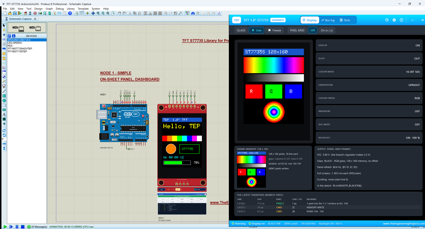
TFT ST7735 Library for Proteus V1.0 (1.8 inch 128x160 + Arduino)


Hello friends, I hope you all are doing great. Today, I am going to share the new TFT ST7735 Library for Proteus V1.0. The 1.8" TFT is the little colour screen you find in so many Arduino kits: 128 x 160 pixels, 65,536 colours, a bright backlight and just a few SPI wires. It is the next step after a character LCD or a small OLED, when your project needs colours, graphs and icons. With this TFT ST7735 Library for Proteus, your sketch draws on a 1.8" TFT that behaves like the real one, including its two famous puzzles: the white screen and the wrong tab.
This is our own model of the module, with the ST7735S controller written from its datasheet: the SPI interface bit by bit, every command with its parameters, the frame memory, the rotations, the colour order and the backlight. You get two devices: TFT Simple, with a live STATUS panel on the schematic, and TFT Advance, with a pop-up window, a bus log and four TFT test tools. The demo runs on our Arduino UNO V4.0, with its serial monitor built into the board.
NOTICE: This library is very special to our team. A colour TFT is a big step from a monochrome display: 20,480 pixels, 16 bits each, a controller with dozens of commands, four rotations and three kinds of glass. We modelled it from the datasheet, tested it pixel by pixel against the real Adafruit library in all four rotations, and made the model tell you what went wrong: a white screen, a wrong tab, a command sent too early. It took our team a lot of hard work and many test runs. Your feedback is the fuel that keeps us going, so please tell us what you think in the comments below or in the LCD Library board of our forum. And if our free libraries help you, you can buy us a coffee. So, let's get started with the TFT ST7735 Library for Proteus V1.0:
What is a 1.8" TFT ST7735 Display?
A TFT (thin-film transistor) display is a colour LCD: every pixel has its own tiny transistor, and three sub-pixels, red, green and blue, filter the white light of the backlight. The 1.8" module has 128 x 160 of these pixels on a red board, with the ST7735S controller on the glass. The controller keeps the picture in its own frame memory and refreshes the glass from it about 80 times a second. Your Arduino only sends it commands and pixel colours over SPI.
The 1.8" TFT at a Glance
| 1.8" TFT ST7735 | |
|---|---|
| Glass | 1.8 inch diagonal, 128 x 160 pixels, a normally-white TN panel |
| Colours | 4,096 (12-bit), 65,536 (16-bit, RGB565) or 262,144 (18-bit) |
| Controller | ST7735S (Sitronix), 132 x 162 x 18-bit frame memory |
| Interface | SPI (the sketch only writes): CS, A0 (data / command), SDA (data), SCK (clock), up to 15 MHz |
| Supply | 3.3 - 5 V on VCC (most boards have a 3.3 V regulator); the logic is 3.3 V |
| Backlight | White LEDs on the LED pin: high = on, PWM dims them |
| Board | Red PCB, 34.5 x 58 mm, 8-pin header, SD card slot with its own 4 pins |
Terms You Will See in This Article
| Term | Meaning |
|---|---|
| RGB565 | A colour in 16 bits: 5 for red, 6 for green, 5 for blue. Adafruit GFX colours are RGB565. |
| Address window | The rectangle the next pixels go into, set with CASET (columns) and RASET (rows) |
| MADCTL | The command that sets the rotation (MY, MX, MV) and the colour order (RGB or BGR) |
| Tab | The colour of the protective film's tab: GREEN, RED or BLACK. It names the kind of glass, and Adafruit's initR() needs it |
| White screen | A TFT that is powered and lit but not driven by its controller shows white |
How the ST7735 Works
Everything goes over SPI. The A0 pin tells the controller what a byte is: with A0 low it is a command, with A0 high a parameter of the last command or, after MEMORY WRITE (2C), pixel data. To draw, a library first sets the address window with CASET (2A) and RASET (2B), sends 2C and then the pixels: the controller fills the window column by column, row by row. A filled rectangle is one window and many identical pixels, which is why fillRect() is fast and drawPixel() is slow: one pixel costs a whole window.
At power-on the controller is asleep and its display is off. After a reset a sketch must wait 120 ms, send SLEEP OUT (11), choose the colour mode with COLMOD (3A, 16-bit for Adafruit GFX), set MADCTL and send DISPLAY ON (29). Adafruit's initR() does all of this, with generous waits. Until then, the glass is not driven, and a TFT glass that is not driven is white.
What's New in TFT ST7735 Library for Proteus V1.0
- Our first colour display: the 1.8" 128 x 160 TFT with the ST7735S, on the red board drawn at twice the real size, with the picture in colour on the schematic.
- The full command set from the datasheet: sleep, display on / off, the address window, MADCTL with its four rotations and the colour order, 12, 16 and 18-bit colour, inversion, idle mode, scrolling, the frame rate.
- The white screen and the wrong tab, as on a real module, with a banner that names the cause.
- The datasheet's waits: a command sent too early after a reset or SLEEP OUT is ignored and flagged.
- A TAB selector on the board: switch between a GREEN, RED and BLACK-tab glass while the simulation runs.
- The backlight with PWM on the LED pin.
- Four TFT test tools on the Advance device: Init check, SPI bus, Speed and Pixels.
- A demo on our Arduino UNO V4.0, with the serial monitor built into the board.
- A compact package: about 1.28 MB, without the C++ source code.
TFT Simple vs TFT Advance
| TFT Simple | TFT Advance | |
|---|---|---|
| Device | TFT18ST7735TEP | TFT18ST7735ADVTEP |
| On the schematic | The board + the TFT STATUS panel | The board only |
| Status | Banner, 10 readouts, the last 6 transfers | A pop-up window: Display, Bus log, Tests |
| Test tools | - | Init check, SPI bus, Speed, Pixels |
| Best for | Seeing the state at a glance | Finding out why a screen is wrong |
Download TFT ST7735 Library for Proteus
Click the button below to download TFT-ST7735-Library-for-Proteus-v1.0.zip (about 1.28 MB, without the C++ source code):
TFT ST7735 Library for Proteus V1.0- README.txt: a detailed guide to the devices, the installation, the demo, the wiring, the test tools, the properties and real hardware.
- Proteus Library Files:
TEPTFT.LIB(the two devices) andArduinoV4TEP.LIBfrom our Arduino Library for Proteus V4.0, with the Arduino UNO V4.0 of the demo. - Proteus Model Files:
TEPTFT.DLLandTEPARDUINO.DLL. - Proteus Simulation:
TFT-ST7735-ArduinoUnoV4.pdsprj,TFT_ST7735_Demo.hex(both UNOs run it) and copies of both DLLs. - Arduino Code:
TFT_ST7735_Demo.ino, the demo sketch. It needs the "Adafruit ST7735 and ST7789 Library" from the Library Manager, which offers Adafruit GFX and Adafruit BusIO too.
No Proteus yet? Read How to Download and Install Proteus 7 and 8. New to libraries? Follow How to Install a New Library in Proteus.
How to Install TFT ST7735 Library for Proteus
- Close Proteus and extract the whole zip file to a normal folder, for example your Desktop.
- Copy the two files from Proteus Library Files into the LIBRARY folder, usually
C:\Program Files (x86)\Labcenter Electronics\Proteus 8 Professional\LIBRARY(on some PCsC:\ProgramData\Labcenter Electronics\Proteus 8 Professional\LIBRARY). - Copy
TEPTFT.DLLandTEPARDUINO.DLLfrom Proteus Model Files into the MODELS folder. If you have our Arduino Library V4.0, its files are the same. - Delete
TEPTFT.IDXfrom the LIBRARY folder if there is one. - Start Proteus, press P and search for ST7735: you get the two devices.
Tip: the demo project needs its .hex file and the two DLLs beside it, so keep the Proteus Simulation folder together. The library was tested in Proteus 8.5; Proteus 7 is not supported.
The 1.8" TFT Board in Proteus
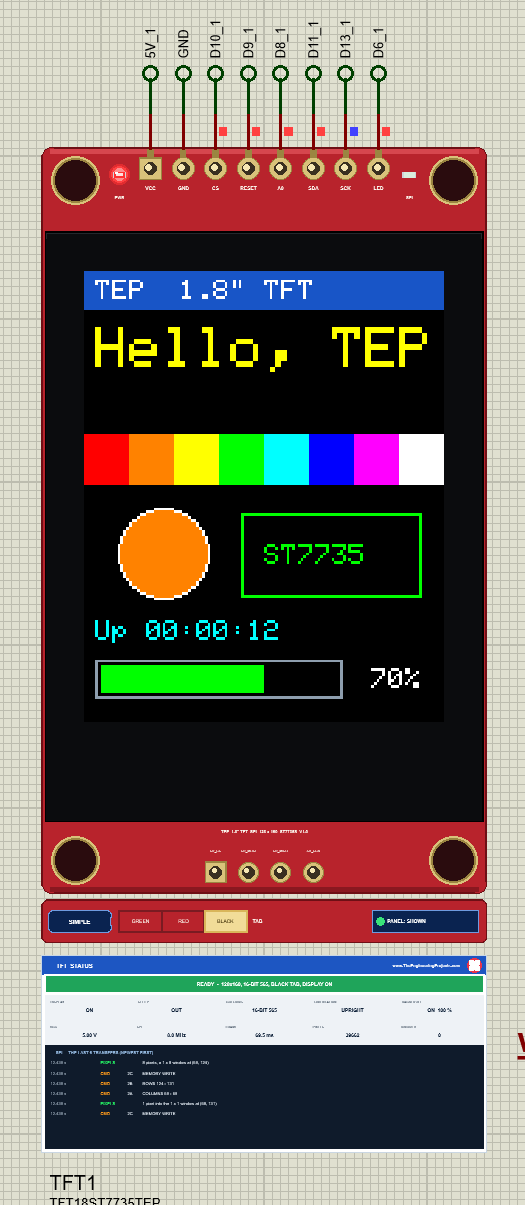
The part looks like the real module: the red board with its four holes, the TFT glass with its black border, the 8-pin header on top and the SD card's 4 pads at the bottom, drawn at twice the real size so the 128 x 160 pixels stay readable. When the simulation runs, the glass shows the picture in colour.
Pinout
| Pin | Function | The demo |
|---|---|---|
| VCC | 3.3 - 5 V (the board regulates it to 3.3 V) | 5V |
| GND | Ground | GND |
| CS | Chip select, active low | D10 |
| RESET | Hardware reset, active low | D9 |
| A0 | Data / command (D/C) | D8 |
| SDA | SPI data in (MOSI) | D11 |
| SCK | SPI clock | D13 |
| LED | Backlight: high = on, PWM dims it | D6 (PWM) |
LEDs, the TEP Strip and the Properties
A PWR LED lights with power and an SPI LED flashes when a byte reaches the TFT. The board has no room for more, so a slim TEP strip under it holds the SIMPLE / ADVANCE badge, the TAB selector (GREEN, RED, BLACK: click it while running to try another glass) and the panel button. The LEDs, the strip and the panels are TEP additions; a real module has none of them. The SD card is not simulated in V1.0; its pads are drawn only.
| Property | Values | What it does |
|---|---|---|
| PANEL | OPEN (default), CLOSED | Simple only: the STATUS panel at the start |
| TAB | BLACK (default), GREEN, RED | The glass of this module: its colour order and window |
The White Screen: Why a TFT Starts White
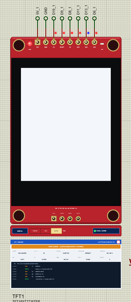
The glass of these modules is a normally-white TN panel: where the controller drives no voltage, the liquid crystal lets the backlight through, and the screen is white. That is why a TFT shows white while it is asleep, while its display is off, and when the sketch never initialised it. The "white screen" is the most common TFT question, and its usual causes are a CS or A0 pin wired wrong, a forgotten tft.initR() or the wrong pins in the constructor.
The model shows exactly that, and the STATUS panel names the cause: NOTHING ON SPI YET (check CS, A0, SDA, SCK), STILL IN SLEEP: SEND SLPOUT (11), DISPLAY OFF: SEND DISPON (29), or SLEEP IN after the sketch's enableSleep(true), as in the picture. The memory keeps the picture, so WAKE brings it back at once.
GREEN, RED or BLACK Tab: Which initR() Does Your TFT Need?
The 1.8" TFTs come with three kinds of glass, named after the colour of the tab on their protective film. They differ in two ways. Some are BGR glasses, with blue and red swapped, which the controller fixes with a bit in MADCTL; and the GREEN-tab glass uses the controller's full 132 x 162 memory but shows only columns 2 - 129 and rows 1 - 160, so the sketch must shift every window by 2 columns and 1 row. Adafruit's initR() knows all three:
| Tab | Colour order | Memory and window | In the sketch |
|---|---|---|---|
| BLACK | RGB | 128 x 160, no offset | tft.initR(INITR_BLACKTAB); |
| RED | BGR | 128 x 160, no offset | tft.initR(INITR_REDTAB); |
| GREEN | BGR | 132 x 162, the glass shows columns 2 - 129, rows 1 - 160 | tft.initR(INITR_GREENTAB); |
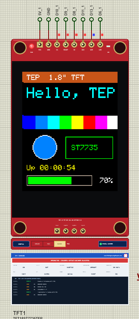
Send the wrong tab and you see what a real module shows: red and blue swapped, and with a GREEN / non-GREEN mix the picture 2 columns and 1 row off, with a stripe of old or random memory at one edge. The model counts the pixels that fall outside the glass or past the memory, the STATUS panel and the Init check name the initR() this glass needs, and the simulation log says it once. With the TAB property or the selector on the strip you can also try the other way round: the same sketch on a GREEN or RED-tab glass.
Backlight, Inversion and Rotation
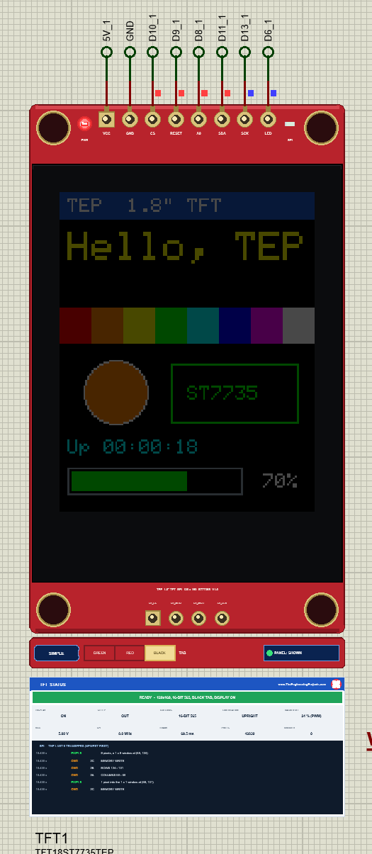
The LED pin drives the backlight. The model measures how long it is high in every 20 ms, so analogWrite() on a PWM pin dims the glass as on a real module. Without the backlight a TFT's picture is all but invisible, and the panel says BACKLIGHT OFF.
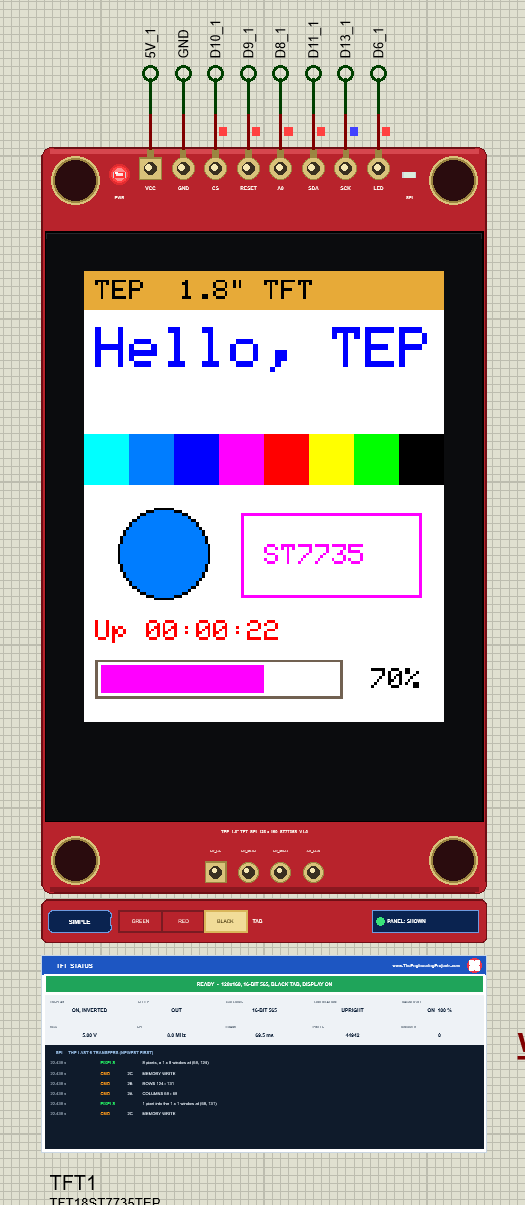
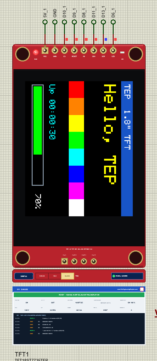
invertDisplay() and setRotation() are single commands: INVON / INVOFF, and MADCTL with its MY, MX and MV bits. The model maps every window through these bits exactly as the controller does; our PC test compares the glass with Adafruit's own picture in all four rotations, pixel by pixel.
TFT Simple: The STATUS Panel
The Simple device keeps a live TFT STATUS panel right under the board. The banner says READY, or what is wrong: NO POWER, WHITE SCREEN with its cause, STILL ASLEEP after a SLEEP OUT that came too early, WRONG TAB, IN RESET or BACKLIGHT OFF. Ten readouts show DISPLAY, SLEEP, COLOURS, ORIENTATION, BACKLIGHT, VCC, SPI (the measured clock), FRAME (the time of a full screen), PIXELS and IGNORED, and the dark log lists the last 6 transfers. The red X closes the panel; PANEL on the strip opens it again.
TFT Advance: The Pop-Up Window
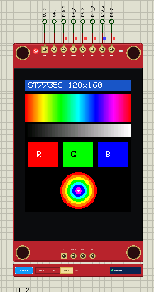
The Advance device keeps only the board on the schematic and opens a TEP pop-up window at Run, with the look of our serial monitor: the tabs Display, Bus log and Tests, Settings, Help and a theme switch.
The Display Page
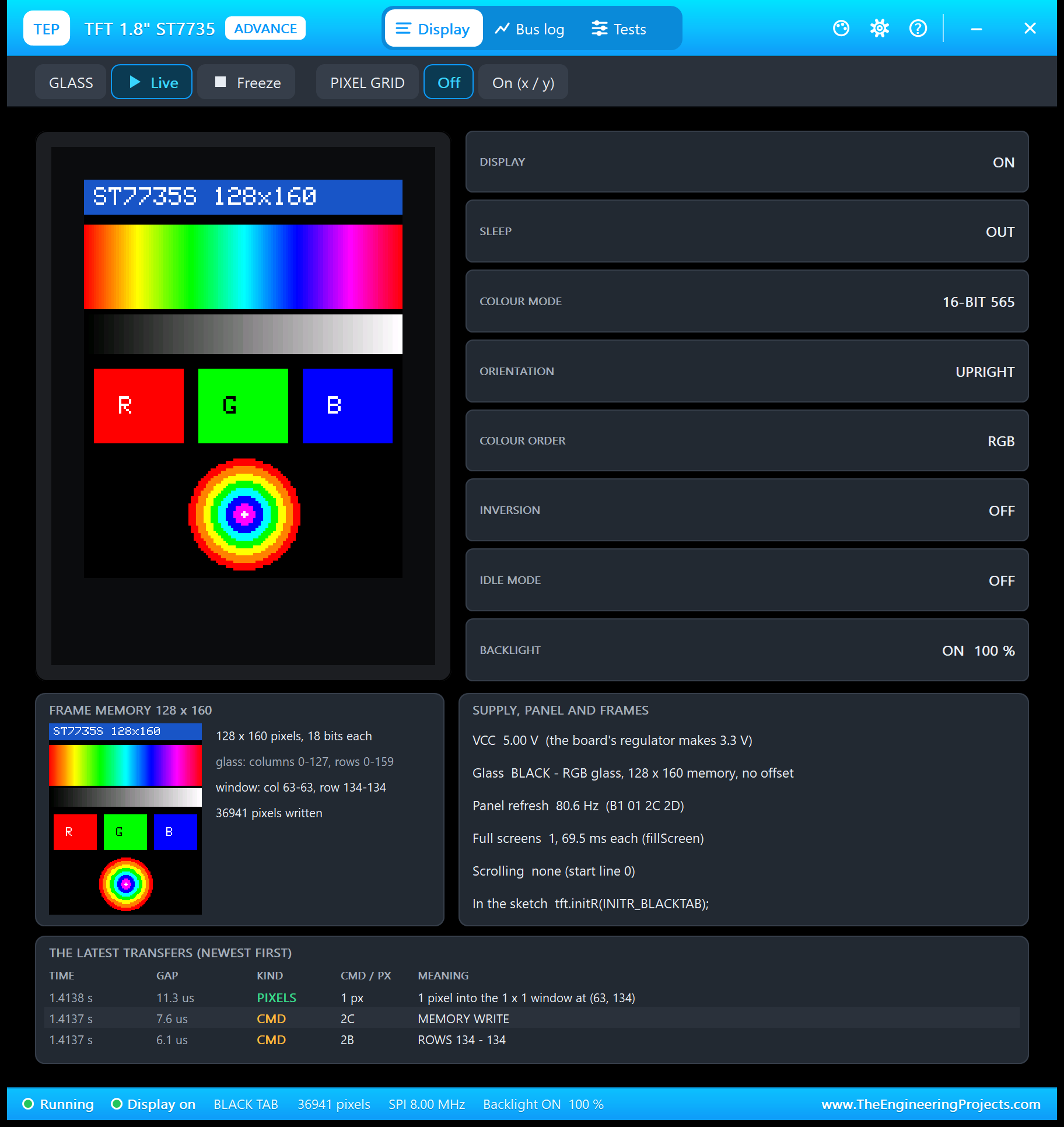
The tiles read the controller: display, sleep, colour mode, orientation, colour order, inversion, idle mode and backlight. The frame memory card shows what the controller holds, and on a GREEN-tab glass it frames the part the glass shows. Freeze holds the picture; the pixel grid adds x / y numbers.
The Bus Log Page
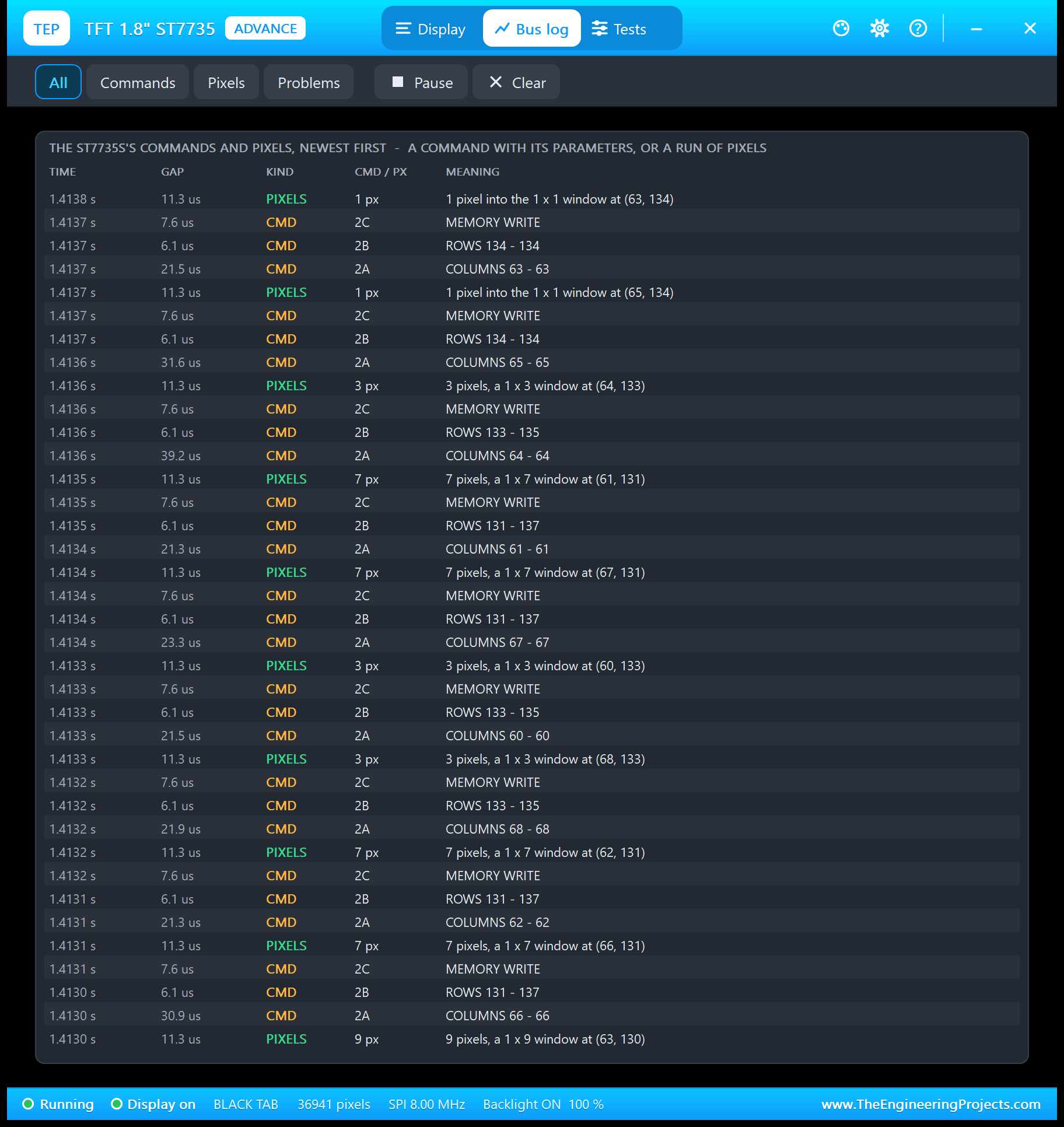
Every command and every run of pixels, newest first: the time, the gap, the kind, the command byte or the pixel count and what it means. The filters show Commands, Pixels or only Problems.
The Tests Page: Four TFT Test Tools
1. Init Check: Is initR() Right for This Glass?
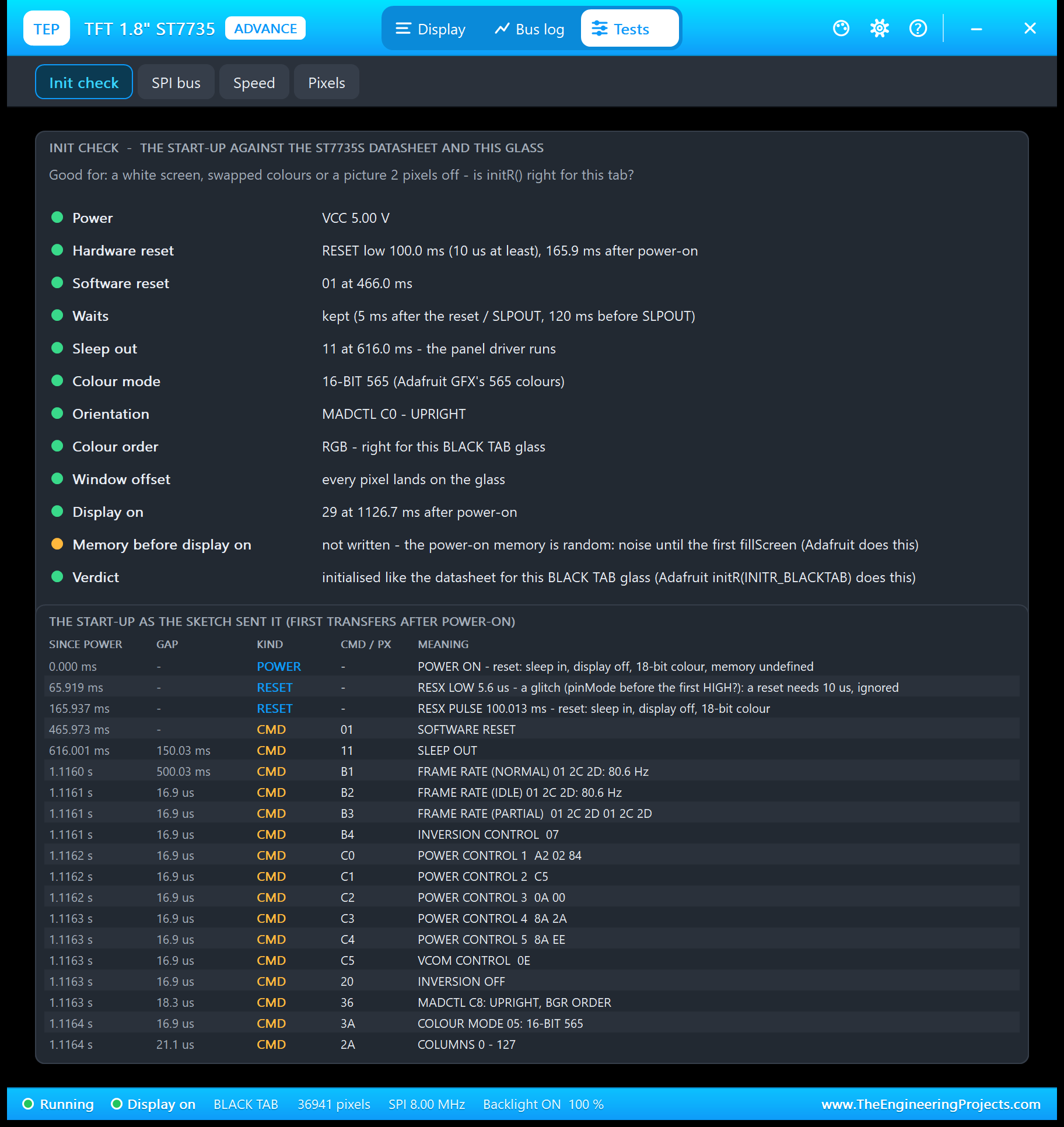
The start-up against the datasheet and this glass: the reset, the waits, SLEEP OUT, the colour mode, MADCTL, the colour order, the window offset and DISPLAY ON. The amber line is a note: Adafruit switches the display on before it draws, so the random power-on memory shows for a moment. With the wrong tab, two lines turn red and the verdict names the fix:

2. SPI Bus: Is the Sketch Talking to This TFT?
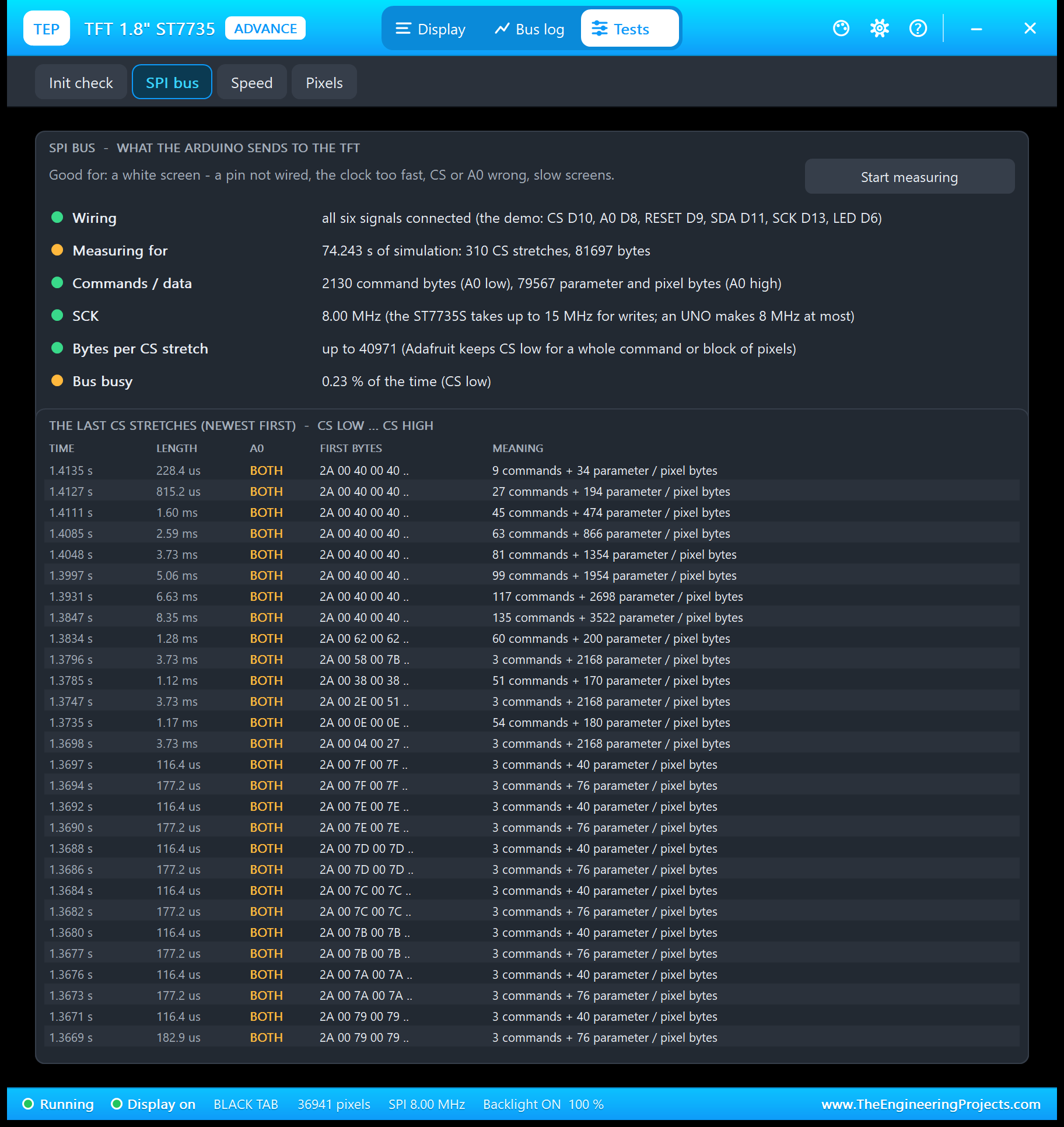
Good for a white screen: which of the six signals are connected, the measured clock (the ST7735S takes up to 15 MHz, an UNO makes 8 MHz), bytes cut by CS, commands sent too early, data with no command before it and unknown commands - the signs of a swapped A0.
3. Speed: How Fast Can the Picture Change?
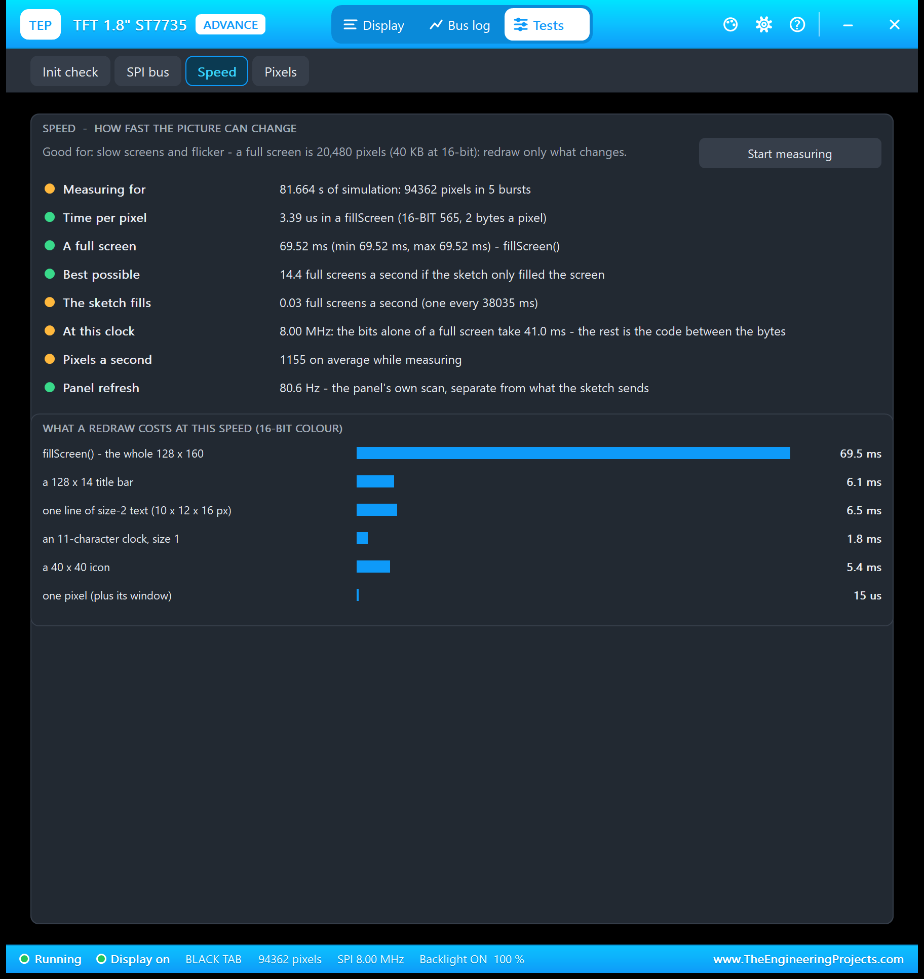
A full screen is 20,480 pixels, 40,960 bytes at 16-bit colour: on an UNO about 70 ms. The bits alone take 41 ms at 8 MHz; the rest is the code between the bytes. So a TFT sketch should redraw only what changes. The cost table shows why the demo's clock (1.8 ms) never flickers while a fillScreen (69.5 ms) would.
4. Pixels: Where Does a Pixel Live?
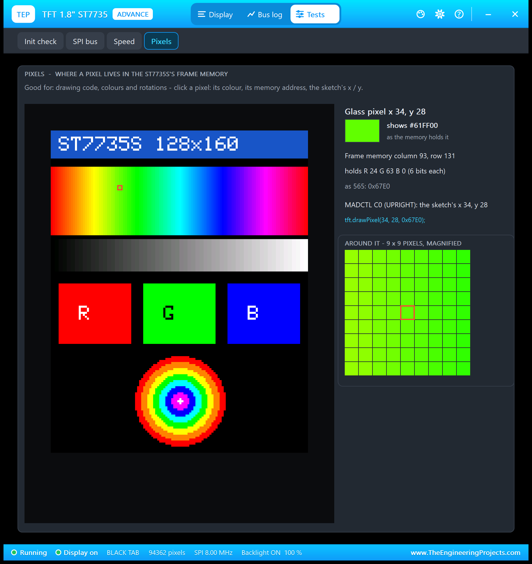
Click a pixel: its colour, where it lives in the frame memory (in rotation 0 the controller mirrors both axes), its 18 bits and its RGB565 value, the sketch's x / y in the current rotation and the drawPixel() line that writes it.
1.8" TFT with Arduino in Proteus
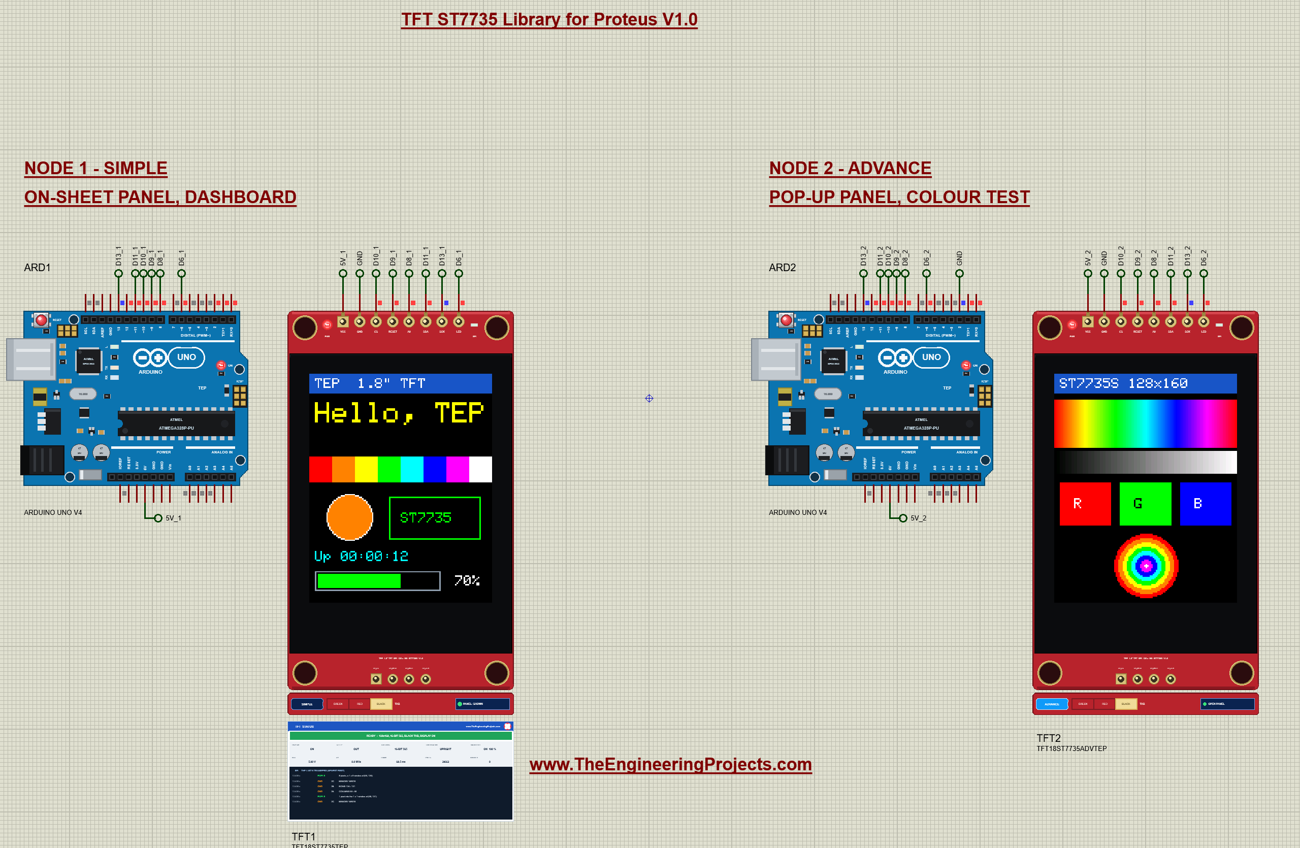
Open TFT-ST7735-ArduinoUnoV4.pdsprj. Two Arduino UNO V4.0 boards from our Arduino UNO Library for Proteus V4.0 run the same sketch; ARD2's D2 is tied to GND, so it starts with the colour test. Each UNO has the serial monitor built in, so there is no Virtual Terminal to wire (see our Introduction to Arduino UNO for its pins).
Wiring
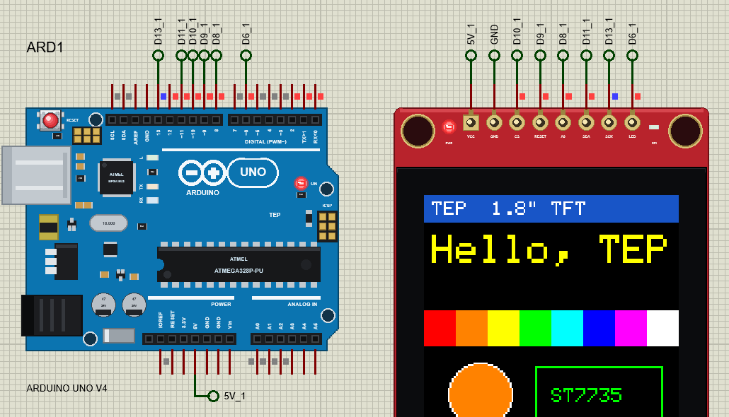
| TFT pin | Arduino UNO |
|---|---|
| VCC | 5V |
| GND | GND |
| CS | D10 |
| RESET | D9 |
| A0 | D8 |
| SDA | D11 (MOSI) |
| SCK | D13 (SCK) |
| LED | D6 (PWM) |
The Arduino Code
The demo uses the Adafruit ST7735 and ST7789 library (version 1.11.0) with the Adafruit GFX library (1.12.6), on the UNO's hardware SPI:
#include <SPI.h>
#include <Adafruit_GFX.h>
#include <Adafruit_ST7735.h>
Adafruit keeps the GREEN tab's offsets when initR() is called again with another tab, so the demo uses a tiny subclass to clear them; that lets its TAB command switch back and forth. A normal sketch simply writes Adafruit_ST7735 tft(10, 8, 9);:
class DemoTft : public Adafruit_ST7735 {
public:
  DemoTft(int8_t cs, int8_t dc, int8_t rst) : Adafruit_ST7735(cs, dc, rst) {}
  void clearOffsets() { setColRowStart(0, 0); }
};
DemoTft tft(TFT_CS, TFT_DC, TFT_RST);             // hardware SPI: SDA = D11, SCK = D13
void initTft() {
if (tab != INITR_GREENTAB) tft.clearOffsets();
tft.initR(tab); // the panel type ("tab"): BLACK, GREEN or RED
tft.setRotation(rotation);
if (inverted) tft.invertDisplay(true);
}In setup(), the backlight goes on with analogWrite(), and D2 picks the first screen:
  pinMode(TFT_LED, OUTPUT);
  analogWrite(TFT_LED, light);                   // the backlight
  pinMode(SCREEN_PIN, INPUT_PULLUP);
  if (digitalRead(SCREEN_PIN) == LOW) screen = TEST;
The most important trick for a TFT: redraw only what changes. The clock is printed with a background colour, so the new digits simply overwrite the old ones, with no fillRect and no flicker:
tft.setTextColor(CYAN, BLACK); // with a background colour: the new digits overwrite the old onesAnd the bar draws only the part between its old and its new length:
  if (filled > was) tft.fillRect(6 + was, y + 2, filled - was, 10, GREEN);
  else if (filled < was) tft.fillRect(6 + filled, y + 2, was - filled, 10, BLACK);
The colour test makes its hue sweep with color565(), which packs 8-bit red, green and blue into one RGB565 value:
tft.drawFastVLine(x, 18, 34, tft.color565(r, g, b));FILL times a full screen with millis(), so you can compare it with the Speed tool:
    const unsigned long t0 = millis();
    tft.fillScreen(BLUE);
    fillMs = millis() - t0;
To change the sketch, export a new HEX file and load it into the UNO; see How to get the HEX file from Arduino. New to Arduino? Start with our Arduino Tutorial for Beginners.
Serial Monitor Commands
| Command | What it does |
|---|---|
| HELP / STATUS | The command list / the tab, rotation, screen, text, bar, backlight, inverse, sleep, display |
| TEXT <text> | The big text (20 characters, two lines of 10) |
| BAR <0-100> | The bar at the bottom (only its changed part is drawn) |
| LIGHT <0-255> | The backlight on D6 (PWM) |
| DASH / TEST / CLEAR | The dashboard / the colour test / a black screen |
| FILL | A timed fillScreen: "fillScreen took N ms" |
| ROTATE <0-3> | setRotation(): 0 / 2 portrait, 1 / 3 landscape |
| INVERT ON / OFF | invertDisplay() |
| SLEEP / WAKE | enableSleep(): the glass goes white / comes back |
| DISPLAY ON / OFF | enableDisplay(): the glass goes white / comes back |
| TAB BLACK / GREEN / RED | initR() again with another tab: GREEN or RED show the wrong-tab faults on this glass |
How to Run the Demo
- Press Run. Both monitor windows and TFT2's pop-up open; move them aside. The glasses are white for a moment, show random pixels when the display comes on, then the dashboard and the colour test.
- Type STATUS, TEXT Hi TEP, BAR 25, LIGHT 60 and INVERT ON in ARD1's monitor; then ROTATE 1, SLEEP / WAKE and TAB GREEN (and TAB BLACK).
- Click the TAB selector on TFT1's strip, and close / open its panel.
- Type FILL in ARD2's monitor and look at the Speed tool; try the other tools on TFT2's pop-up.
TFT ST7735 Proteus Simulation Results
The Built-in Serial Monitor in Its Simple Interface
Each Arduino UNO V4.0 carries its own copy of our TEP Serial Monitor Advance, wired inside the board to D0 / D1 like the USB chip of a real UNO. Its window, "TEP Arduino UNO - ARD1", opens at Run, and a click on the board's USB port opens it again. The screenshots show its Simple interface: only the log and the line to send.
- Switch to it: press Ctrl+Shift+U, or use the monitor's ... menu.
- Back to the full view: press Esc; the full view has the Board, Monitor and Plotter tabs.
Read all about the monitor in TEP Serial Monitor Advance for Proteus.
ARD1: STATUS
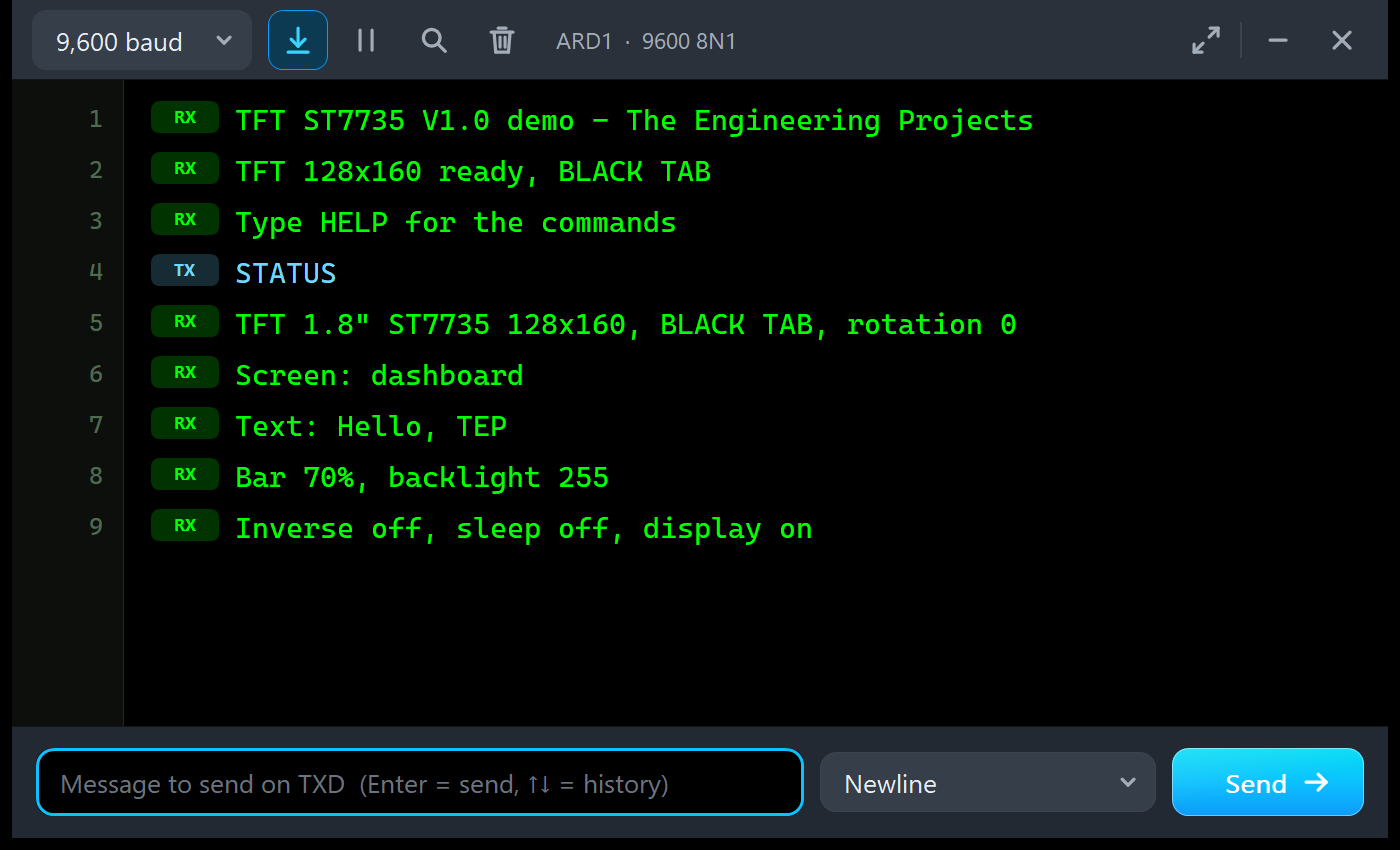
TFT ST7735 V1.0 demo - The Engineering Projects
TFT 128x160 ready, BLACK TAB
Type HELP for the commands
STATUS
TFT 1.8" ST7735 128x160, BLACK TAB, rotation 0
Screen: dashboard
Text: Hello, TEP
Bar 70%, backlight 255
Inverse off, sleep off, display on
ARD2: FILL
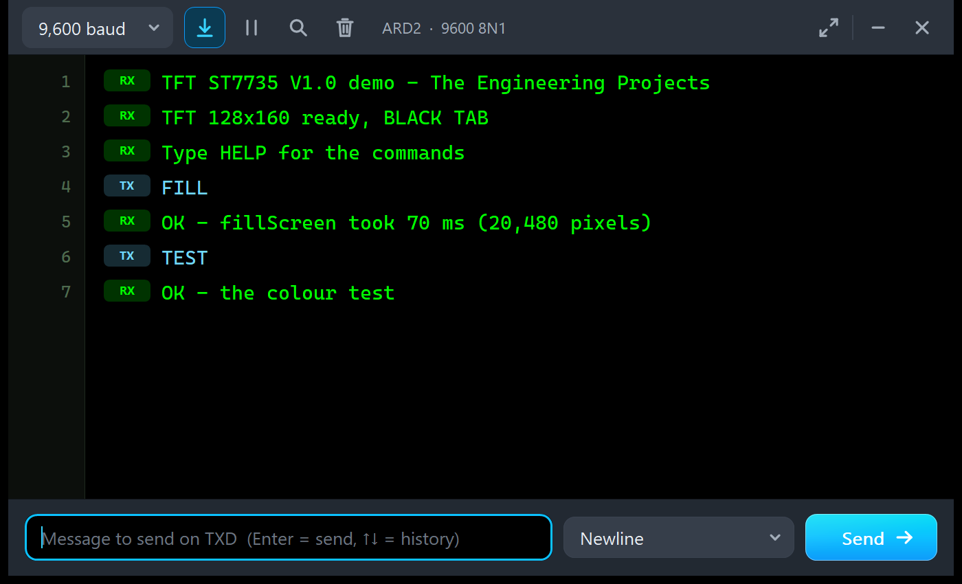
TFT ST7735 V1.0 demo - The Engineering Projects
TFT 128x160 ready, BLACK TAB
Type HELP for the commands
FILL
OK - fillScreen took 70 ms (20,480 pixels)
TEST
OK - the colour test
The sketch measures 70 ms with millis(), and the Speed tool 69.52 ms on the bus: the same fillScreen seen from both sides.
Troubleshooting
- The glass stays dark and the PWR LED is off: no power. Check VCC and GND (the module needs 3.3 - 5 V).
- WHITE SCREEN - NOTHING ON SPI YET: check SCK on D13, SDA on D11, CS and A0, and that the sketch calls
tft.initR(). The SPI bus tool lists the pins that are not connected. - WHITE SCREEN - STILL IN SLEEP or DISPLAY OFF: SLEEP OUT (11) or DISPLAY ON (29) was never sent;
initR()sends both. - STILL ASLEEP - SLPOUT CAME TOO EARLY: wait 120 ms after a reset before SLEEP OUT.
- WRONG TAB: swapped colours or a picture 2 pixels off: change INITR_..TAB in the sketch, or the TAB property to the module you really have.
- BACKLIGHT OFF: drive the LED pin high, PWM it, or wire it to 3.3 V / 5 V.
- Random pixels at the start: the memory before the first fillScreen; normal.
- The part or the UNO is not simulated, or no monitor window: TEPTFT.DLL or TEPARDUINO.DLL is missing from MODELS and the project folder; a closed monitor opens again with a click on the UNO's USB port.
- The Advance pop-up does not appear: click OPEN PANEL on the strip.
Things to Know Before Using a Real 1.8" TFT
The demo sketch uses only SPI, the Adafruit libraries and Serial, so it runs on a real UNO and 1.8" TFT too. Keep in mind:
- Find your tab: start with INITR_BLACKTAB; if the colours are swapped or a noise stripe shows at an edge, try GREEN or RED.
- 3.3 V logic: most red boards have a regulator but no level shifter. Many people wire a 5 V UNO directly, but 1 kohm resistors in series with the signals, or a 74HC4050, are safer.
- The backlight: check whether your board has a resistor on LED; if not, add one (e.g. 100 ohm).
- Speed: about 70 ms for a full screen on an UNO; draw only what changes.
- RAM: Adafruit_ST7735 keeps no picture in RAM; the demo uses 879 bytes of the UNO's 2,048.
- The SD card has its own SPI pins: wire them to the same bus with another CS pin.
Limitations of the Simulation
- Not modelled: reading from the TFT (no reply on SDA; drivers never read), the partial mode's non-display area, the effect of the gamma, power and VCOM settings on the picture, the panel's response time, timing violations shorter than the simulation's edges, the current draw, damage from 5 V signals or a reversed supply (the model only warns), and the SD card.
- The board is drawn at twice the real size; the LEDs, the strip with the badge, the TAB selector and the panel button, and the panels are TEP additions.
- The model is our own implementation, written from the ST7735S datasheet. ST7735S is a Sitronix part; this library is not made or endorsed by Sitronix, Adafruit or Labcenter.
- Licences: the demo sketch uses Adafruit ST7735 and ST7789 1.11.0 (MIT licence), Adafruit GFX 1.12.6 (BSD licence) and Arduino's SPI library. The HEX file contains them and the Arduino AVR core 1.8.6, which includes LGPL-licensed code; its source code is on GitHub. The README holds the Adafruit licence texts.
- Tested in Proteus 8.5 in October 2026 (the demo as shipped on two Arduino UNO V4.0 boards with their built-in monitors, the dashboard and the colour test, the Serial commands, the backlight, INVERT, ROTATE, SLEEP / WAKE, the wrong tab, the panel, the pop-up and the four tools, and every screenshot here; about 0.3 x real time with the pop-up and both monitors open on a busy PC) and with automatic PC checks, 0 failed: 83 with the real demo sketch and the unmodified Adafruit libraries talking bit by bit to the model, where the glass equals Adafruit's own GFXcanvas16 pixel by pixel after every command in all four rotations, 11 on the pop-up pages, and the demo project read back from disk. Proteus 7 is not supported.
Looking for a smaller display? Our Nokia 5110 LCD Library for Proteus V1.0 has the classic 84 x 48 graphic LCD, and our OLED Library for Proteus V1.0 has the 0.96", 0.91" and 1.3" OLEDs in one library.
So, that was all about the TFT ST7735 Library for Proteus V1.0. I hope the white screen, the tab and the speed of a colour display are clear now, so your TFT works the first time you wire a real one. If you use the TFT ST7735 Library for Proteus in a project, please share your feedback in the comments or in our forum, and if you have any questions, ask in the comments and I will help you out. Till the next tutorial, take care and have fun!
Comments
0