

Hi learners! I hope you are doing great. Today, I am going to share the second version(V2.0) of the LCD library for Proteus. We have already shared the LCD V1.0 Library on our blog. Along with appreciation, we also get some complaints/suggestions about that library. So, we have designed a better version of the LCD library by keeping the suggestions in mind.
Version 2.0 has error-free working, better pinout prints, and is identical to the real-world LCD. We have also removed our website link from the LCD. This library includes two alphanumeric LCDs in it i.e. LCD 16x2 and LCD 20x4.
If you don't have any experience with the LCD, no need to worry as we will guide you from scratch. Before installing the LCD, let's first have a look at its brief introduction:
| Where To Buy? | ||||
|---|---|---|---|---|
| No. | Components | Distributor | Link To Buy | |
| 1 | Battery 12V | Amazon | Buy Now | |
| 2 | Resistor | Amazon | Buy Now | |
| 3 | LCD 16x2 | Amazon | Buy Now | |
| 4 | LCD 20x4 | Amazon | Buy Now | |
| 5 | PIR Sensor | Amazon | Buy Now | |
| 6 | Arduino Uno | Amazon | Buy Now | |
What is Liquid Crystal Display?
- A liquid crystal display or LCD is a flat board of liquid crystals that are sandwiched between polarizers. When the electric field is applied to it, this material rotates according to the polarization and allows the light to pass through it. As a result, the display is shown on the LCD board.
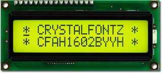
- A simple 16x2 LCD is shown in the below figure:
- The LCD is used in electrical/electronic projects to display sensors' data, statuses, alerts, notifications etc.
- We can interface this LCD with any microcontroller i.e. Arduino, PIC, Atmel, Raspberry Pi, STM32 etc.
- Some of the advantages are low power consumption, durability, and long life.
Let's have a look at the pinout of LCD:
LCD Pinout
Both of these LCDs(16x2 and 20x4) have similar pinouts and a simple basic circuit needs to be designed in order to operate them. There are a total of 16 pins present in LCD used for different purposes. The below table has the complete description of LCD Pinout:
Serial |
Pin |
Functionality |
Description |
1 |
VSS |
Ground |
This pin is connected to the ground terminal of the circuit. |
2 |
VDD |
Power Supply |
It is connected to the positive voltage(+5V) and is responsible for the power supply to all pins. |
3 |
VEE |
Voltage Emitter |
It is used to control the contrast of LCD. it applies the negative voltage and thus controls the electric field of the LCD. |
4 |
RS |
Register Select |
It selects the LCD register. LCD has two registers: an instruction register and a data register. |
5 |
RW |
Read or write |
The read-and-write operation is done through this pin. if set to HIGH then LCD is in reading mode and LOW means it is writing the data. |
6 |
E |
Enable |
Enables the working of LCD. If HIGH then allow the display and if LOW then disable it. |
7-14 |
D0-D7 |
Data bits (Pins to deal with the data) |
Data is sent to the LCD in a parallel manner. These pins send this data and out of these, D0 is the least significant and D7 is the most significant. |
LCD Library For Proteus
The installation of the LCD V2.0 is simple. The first step is to download the library files. I believe you have Proteus installed. So, click the below button to download the Proteus Library zip file.
Adding Proteus Library Files
- Once downloaded, go to the file location and extract content from the zip file.
- Open the folder named "Proteus Library Files" and here you will find two library files in it, named:
- LCDLibraryTEPV2.0.IDX
- LCDLibraryTEPV2.0.LIB
- Simply copy these files in the Library folder of Proteus software. Go to your C drive>Program Files>LabCentre Electronics>Proteus Professional> Library.
- If you are having any difficulty installing the library, you should a look at How to install a new Library in Proteus.
The zip file also contains the project, where we simply connected both the LCDs with Arduino, so that you could check their working. Moreover, code is also present in the file.
LCD V2.0 in Proteus
Once the Library is installed, you need to open your Proteus software. If it's already open, you have to restart it. Now follow the instructions.
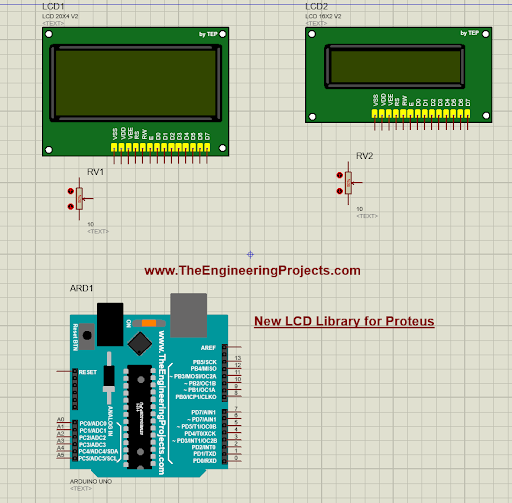
- Go to the pick library by clicking on the “P” button.
- In the dialogue box, type "LCD TEP" and you will get the below results:
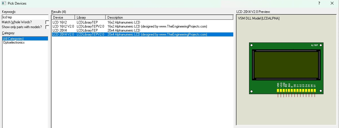
I have installed both versions therefore, I am getting four options. I will choose the LCD 20X4 V2.0 and LCD 16X2 V2.0.
Click on the components and simply place them on the working sheet of Proteus, it will appear as shown below:
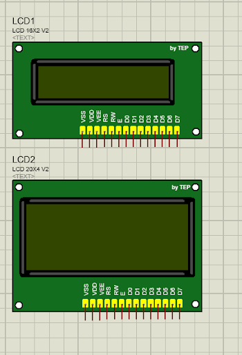
- I hope you guys will enjoy this new look without the site's link.
Now, let's design an LCD simulation in Proteus:
LCD Simulation in Proteus
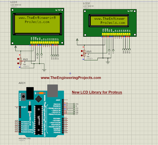
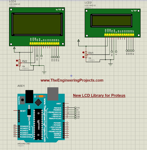
Now, let's design a simple LCD simulation, where we will interface it with an Arduino UNO board. We will display our website's link on the LCD. So, let's design the circuit:
Interfacing LCD with Arduino
Go to the pick library and select the following components:
- LCD 20X4
- LCD 16X2
- Arduino
- POT-HG
- Place the Arduino and other components in the working area, as shown in the below image:
- Go to Terminal mode and select the Power & Ground terminal for both LCDs.
- In order to design a neat circuit, I have connected the “Default” terminal with each pin, instead of wires.
- The complete circuit diagram is shown in the below figure:
Now let's design the Arduino code to display data on these LCDs:
Arduino Code for LCD Simulation
Now, open your Arduino software, I hope you have it installed. Paste the below code in it, I have also added this code in the zip file.
#include
// initialize the library with the numbers of the interface pins
LiquidCrystal lcd(13, 12, 11, 10, 9, 8);
void setup() {
// set up the LCD's number of columns and rows:
lcd.begin(16, 2);
// Print a message to the LCD.
lcd.setCursor(1,0);
lcd.print("www.TheEngineering");
lcd.setCursor(4,1);
lcd.print("Projects.com");
}
void loop() {
}
Add HEX File in Proteus
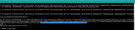
The next step is to get the Hex File from Arduino IDE and add in the Proteus. For this, follow these steps:
- Verify the Arduino Code by clicking the "Verify" button and the output pane will give the location to the hex file, as shown in the below figure:
- In the proteus software, double-click on the Arduino board to open its Properties Panel.
- Paste the HEX file in the program file section and press OK.
LCD Simulation Results
- Now, the LCD simulation is ready to run.
- You can see in the code, we have printed the TEP link on the LCD screen.
- Once you play the circuit, the LCDs will display the message, as shown in the below figure:
If you have followed all the steps, I am sure your project will run successfully. I hope it was helpful to you. You must practice it more and try to make different projects. So, that was all for today, will meet you guys in the next tutorial. Take care!!!
