Hi learner! I hope you are doing great. Today, I am sharing version 3.0 of the PIR sensor library for Proteus. We have already shared V1.0 and V2.0 of the PIR Sensor Library. PIR Sensor V1.0 Library for Proteus adds a digital PIR Sensor in Proteus, while the PIR Sensor V2.0 Library adds an analog PIR Sensor to simulate. These libraries were loved by the users and this motivated us to work more on it.
PIR V3.0 is analog in nature, has an error-free structure and the Pinout structure is better organized. Moreover, the design is improved a little bit and we have omitted the website link from the sensor to make it look professional.
Same as the previous version, this PIR has four pins and the details of each of them will be discussed in detail later. Therefore, don’t worry if you have no experience with the sensors in Proteus. Let's discuss the basic introduction of the PIR sensor:
Introduction to PIR Sensor
- A passive infrared sensor or PIR is a motion detector that detects the changes in the infrared light radiating from the bodies.
- When the body moves in the range of the PIR Sensor, the change in the environmental infrared waves is sensed by the PIR.
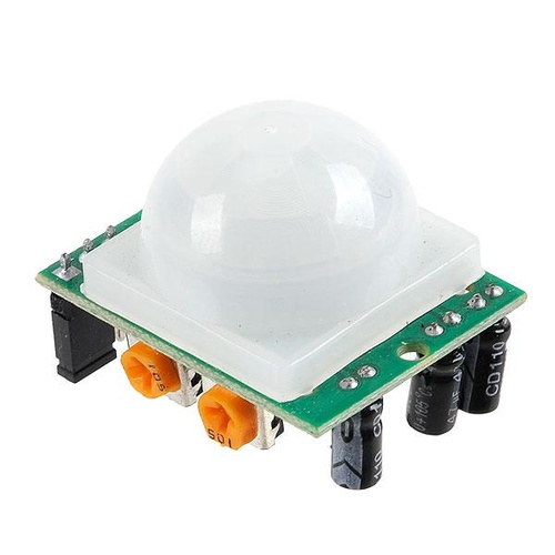
- In the PIR Sensor, two pyroelectric sensors are placed behind the lens to detect the change in IR level.
- PIR Sensors are called “Passive” because they don’t create any infrared light but are only used to detect it.
- PIR sensors may be digital or analog. In the digital sensor, the output is always in the form of only two conditions ON or OFF (1 or 0) and gives only the detection of motion.
- On the other hand, analog sensors give the degree of motion.
Here are a few of the Embedded Projects in which we have used PIR sensor, you should have a look:
- PIR Sensor Arduino Interfacing
- Motion Detection with PIR Sensor and ESP32
- Motion Detection with PIR Sensor & Raspberry Pi 4
PIR Sensor Pinout
Generally, the real-time PIR sensor has three pins and these are used for different purposes. It is important to connect all of these correctly to get the output. Here is the description of each pin:
- The VCC pin is connected to the positive voltage supply, normally +5V.
- The GND pin is attached to the negative voltage supply.
- The output pin generates the signal only when the motion is detected.
If these pins are set properly, the circuit works fine. The sensor we have designed has a fourth terminal called TestPin. Proteus is the simulation software therefore, it is not possible to provide the motion. TestPin is used to provide the motion by the user.
PIR Senosr Library in Proteus
We know that Proteus does not have a built-in PIR sensor therefore, we have created this library so that you may use it in the circuits. For this, you have to download and install the PIR Sensor library in your proteus software. Here is the download link for the installation, simply download the zip file.
PIR Sensor Library for Proteus V3.0
Adding Proteus Library Files
- Once the library is installed, go to the file location and extract the content.
- Go to the folder named “Proteus Library Files” and open it.
- Here, you will get two files for the library named:
- PIRSensorV3.0TEP.IDX
- PIRSensorV3.0TEP.LIB
- PIRSensorV3.0TEP.HEX
- Copy these files and paste in the Library folder of Proteus software. You will find it at C drive>Programming files>LabCenter Electronics>Proteus Professional>Library.
- If you are facing any difficulty in installing the library, you can see the How to install a new library in Proteus.
The zip file has another folder named “Proteus simulations” where you can find the resources of projects containing simple working of PIR Sensor and PIR Sensor interfaced with Arduino UNO and LCD.
PIR V3.0 in Proteus
Now, open your Proteus software and if was opened already, restart it to index the PIR sensor library with it.
- Click on the “P” button to pick the components.
- Write PIR sensor in the dialogue box, it will show you the options to select. I have downloaded the previous versions as well so I am getting all the options:

- I am choosing all the PIR Sensor V3.0 by clicking on it one after the other. You can choose according to your choice.
- Now, click on the PIR sensor and double-click on the working area Where you want to place the PIR sensor.
- All the types of PIR Sensor V3.0 are the same but the color is different to make them more attractive. I am placing all of these on my working sheet to show you the difference.
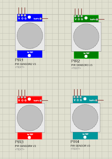
Here, you can see it has the minimum text on it and the size is smaller than the previous version so that you may fix it in your large and complex projects without any problem. Now, I am deleting two sensors and will work only on the remaining two.
Providing HEX File for PIR Sensor V3.0
This sensor will not work unless you add the HEX file to it. For this, follow the steps given:
- Double-click the sensor to open the properties panel.
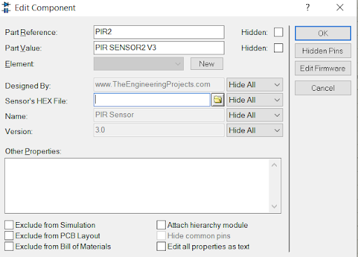
- Here, click on the folder sign. It will prompt you to the folders of your system. You have to provide the path for the PIRSensorV3.0TEP.HEX you have just extracted from the zip file.
PIR Sensor V3.0 Simultion in Proteus
Now, we will design two circuits of PIR sensor V3.0. The first will be simply made with the basic components and the other one will have the Arduino UNO interfaced with the LCD so that we may get the more user-friendly results. Let's hover over your Proteus workspace to make the simple PIR circuit.
Components Required
The following Components are required for setting the PIR sensor.
- PIR sensor
- Inductor
- Capacitor
- Potentiometer
Go to the “Pick library” button type the names of the components one by one and select them.
Setting the PIR Sensor
- Set the inductor and capacitor with the PIR Sensor’s output pin.
- Take a potentiometer and set it with the TestPin.
- Go to the terminal mode and get power and ground terminals. Attach these with the respected elements.
- To check the output, we have to insert an AC voltmeter from the “virtual instrument mode”.
- Connect all the components with the help of connecting wires.
- Now your circuit must look like this:
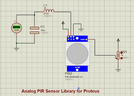
The real-time PIR sensor does not require the LC circuit but in Proteus, the peak-to-peak values are generated which needs to be converted into RMS values and that's why we used this LC filter.
Now, hit the play button to check the values of the PIR sensor.
Interfacing Arduino with PIR Sensor V3.0
Now, if you want to make your project more user-friendly, an LCD is the best option. To link these, I have used the Arduino UNO and through the code, the values of the PIR reading are shown on the LCD. I have interfaced the TEP LCD 20X4 with the Arduino and simply connected the output of PIR with the analog pin of Arduino. The circuit now looks like the following image:
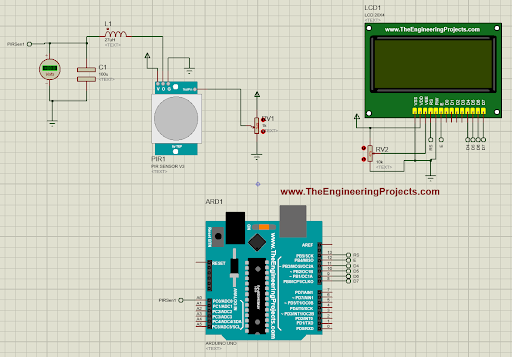
Arduino Code for PIR Sensor
Once your simulation is ready, you have to paste the code into Arduino.exe.Open your software and paste the given code there.
#include
// initialize the library with the numbers of the interface pins
LiquidCrystal lcd(13, 12, 11, 10, 9, 8);
int SensorPin = A0;
void setup() {
// set up the LCD's number of columns and rows:
lcd.begin(20, 4);
// Print a message to the LCD.
lcd.setCursor(1,0);
lcd.print("www.TheEngineering");
lcd.setCursor(4,1);
lcd.print("Projects.com");
lcd.setCursor(0,2);
lcd.print("Analog Value: ");
lcd.setCursor(0,3);
lcd.print("Voltage: ");
}
void loop() {
int SensorValue = analogRead(SensorPin);
float SensorVolts = analogRead(SensorPin)*0.0048828125;
lcd.setCursor(14, 2);
lcd.print(SensorValue);
lcd.setCursor(9, 3);
lcd.print(SensorVolts);
lcd.print(" V");
delay(1000);
// sensorValue = analogRead(sensorPin);
// lcd.setCursor(4,2);
// lcd.print(sensorValue);
// delay(1000);
}
The same code is also given in the zip file you have downloaded.
Inserting the HEX File in Proteus
When the code is run on the Arduino.exe, it provides the HEX file in the compilation details. You have to copy the address of the HEX file and insert it into the Arduino in Proteus. For this, follow these steps:
- Verify the code by clicking on the check button. The compilation will start if there are no errors.
- Go to the black compiler window at the lower area of the screen.
- Copy the address of the HEX file.

Go to the Proteus and double-click on the Arduino to open the properties panel. Now paste the path of the HEX file here. The circuit is now ready to work. If you are stuck at this step, you should have a look at How to get Hex File from Arduino.
PIR Sensor V3.0 Results
Now it's time to run the simulation. So hit the Play button and you will see that the output is shown on the screen.
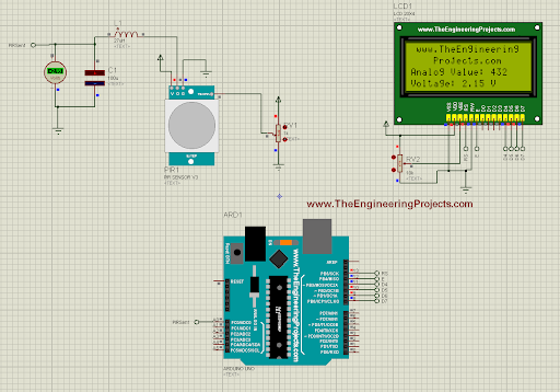
The analog values can be changed through the potentiometer of the testPin. The analog values of the motion sensor along with the voltages are shown on the LCD. I hope your circuit worked the same as mine. If you are facing any type of issue, you can contact us.


 Proteus
 syedzainnasir
 0 Comments


 2.3k
2.3k
 953
953
 921
921
 2.1K
2.1K

