Motion Detection with PIR Sensor & Raspberry Pi 4


Hello friends, I hope you all are doing well. Today, I am going to share the 4th chapter of Section-III in our Raspberry Pi programming course. In the previous lecture, we studied the Interfacing of IR sensor with Raspberry Pi 4. In this guide, you'll learn how to interface a PIR sensor with Raspberry Pi to create a motion detector. A passive infrared (PIR) sensor is a straightforward yet effective tool for motion detection.

As a bonus, a piezo speaker will play an audio clip whenever motion is detected. GPIO pins are required for both of these accessories. This tutorial is a great starting point for those who have never worked with electronic components and circuits.
These sensors are used in traditional, old-generation security systems. In contrast, video is used in most of today's monitoring systems. So, let's get started:
Project Description
Today, we are going to design a security project, where we will sound an alarm using a piezo speaker, if any motion is detected by the PIR Sensor. We will use Raspberry Pi 4 for today's tutorial.
Here's the video tutorial:
Components Required
Here's the list of components, used to design this motion detector:
- Raspberry Pi 4.
- PIR Sensor.
- Piezo Speaker.
- 100-ohm resistor.
What is a PIR sensor?
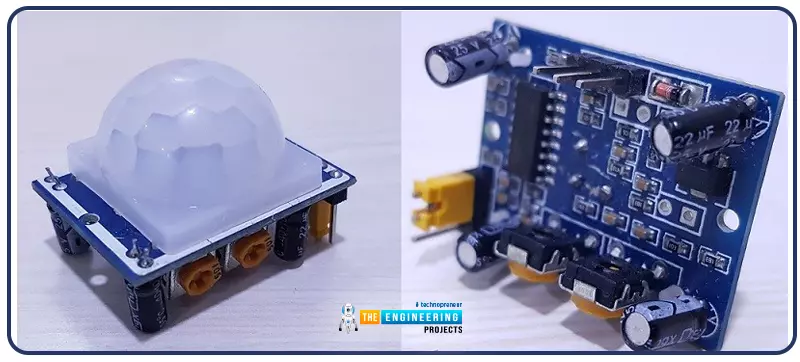
- Infrared motion detectors, also known as passive infrared (PIR) sensors, are a type of motion sensor that makes use of IR light to identify and locate the source of motion.
- A Fresnel lens is mounted on top of the PIR sensor, which increases the sensor's field of view to 120 degrees.
- The sensor can detect human movement within an 8-meter radius around it.
- Anything, alive or otherwise, having a temperature greater than zero degrees Celsius emits infrared radiation.
- The wavelength of infrared radiation is far greater than that of visible light, making it invisible to the human eye.
- Passive infrared (PIR) sensors are specifically designed to detect these heat signatures.
As their name implies, passive motion sensors don't put out any rays of their own but instead pick up the infrared radiations emitted by other objects, making them ideal for use in intruder alarm devices. However, active detectors may produce and detect infrared light at the same time.
PIR Sensor Pinout
The PIR motion sensor has three pins:
- Pin1 is Vcc: We need to provide +5V to this pin.
- Pin2 is the data Pin: It's a digital Pin and sends sensors' data.
- Pin3 is GND: We need to connect it to the ground.
PIR Sensor Working Principle
In PIR Sensor, crystals sensitive to infrared light are used as sensors. As its a passive IR sensor, the sensor doesn't emit any IR waves, instead, it waits for the infrared-emitting object.
The IR sensing component consists of two subassemblies, A and B.
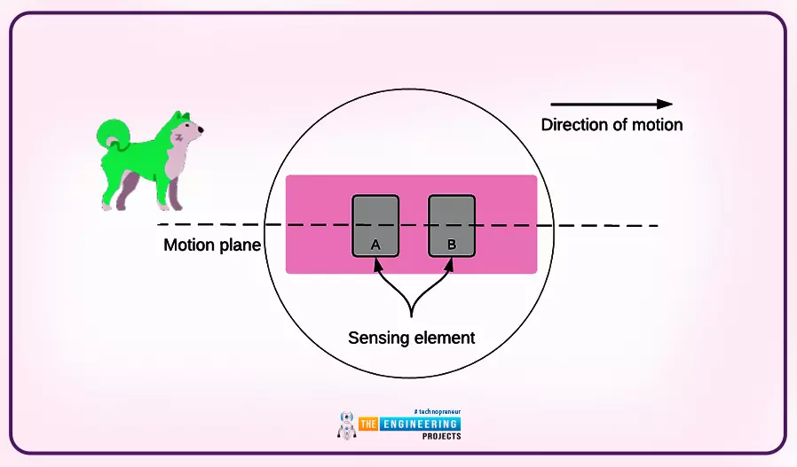
When there is no motion, the two detectors pick up identical infrared readings, which cancel out one another. Sensing element A will pick up the presence of infrared light, when an infrared-emitting object, such as a dog, enters the sensor's field of vision. Since the intensity of the infrared light striking sensing element B is still relatively low, the resulting differential change is positive.
As the object moves past the sensor, the intensity of the infrared light falling on sensing element B will be greater than that falling on sensing element A, resulting in a negative differential change. The BISS0001 logic chip onboard detects and amplifies this potential difference before outputting it as a digital signal.
When the infrared detector detects movement, it sends a signal to the microcontroller through the data input, which goes HIGH.
PIR Sensor Adjustments
The Motion Sensor also has two potentiometers that may be adjusted to fine-tune the PIR sensitivity and the amount of time its output signal stays high after detecting motion.
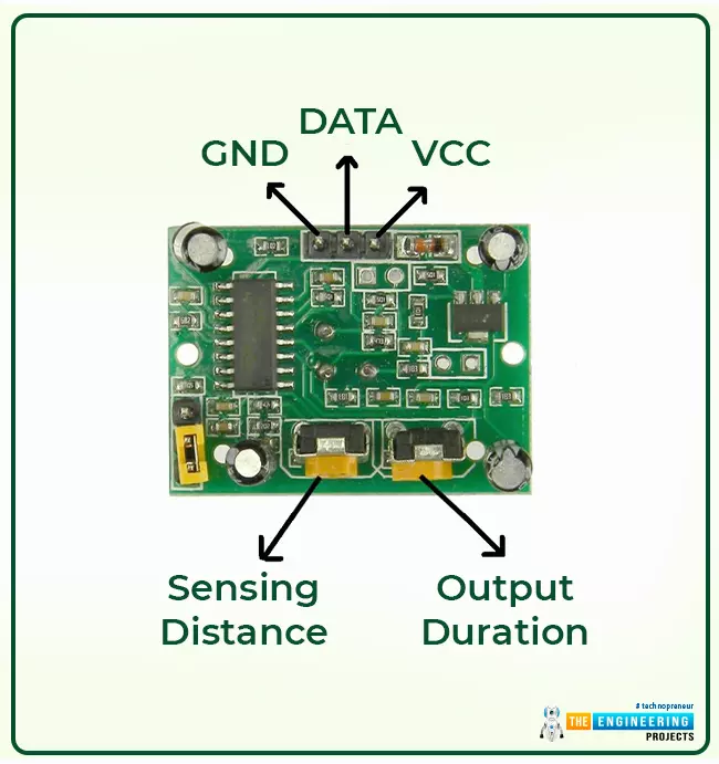
As shown in the above figure, the left potentiometer allows you to adjust the sensor's sensitivity. Distances between 3 to 8 meters are adjustable. The Potentiometer can be turned clockwise to enhance the detection range and counterclockwise to decrease it.
The second Potentiometer controls the duration of the motion sensor's HIGH output. Times might be anything from 0.3s to 600s. The POT can be adjusted by turning it clockwise(to increase time) or counterclockwise (to decrease time).
Circuit Diagram of PIR Sensor with Raspberry Pi 4
We will design a simple Motion Detection Project using PIR Sensor & Piezo Speaker with Raspberry Pi 4. It's a simple security system where the PIR sensor will detect motion and Piezo Speaker will trigger the alarm.
A piezo buzzer is an easy-to-use speaker that makes noise whenever an electric current passes through it. The buzzer will sound an audible alert when the motion is detected.
Here's the circuit diagram of PIR Sensor with RPi4:
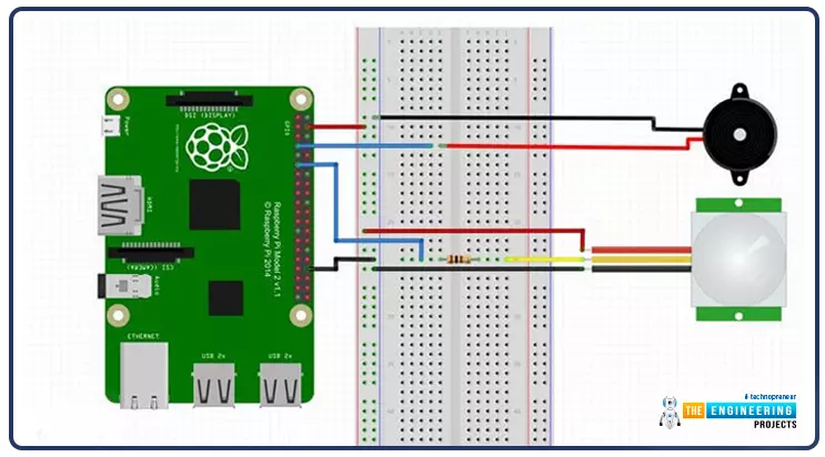
Just follow these steps to build the circuit.
- Connect the Ground Pin to the breadboard's ground rail.
- Connect the breadboard's positive rail with the +5v Pin.
- One wire of the Piezo buzzer should be connected to Pin7 of RPi and the second wire to the ground.
- Connect Pin11 of RPi4 to the breadboard with a wire. Connect a resistor of 100 ohms to the wire's terminal. The PIR sensor's yellow wire should be connected to the other end of the resistor.
- The PIR sensor's red wire must be connected to the breadboard's 5V line, while the black wire must be connected to the ground rail.
Python Code for PIR Sensor with RPi4
We begin by importing the GPIO and time Python libraries, allowing us to communicate with the GPIO rail and halt the script. For our first two variables, which I have aptly dubbed "pins," we provide a reference to our physical ports. Our sensors' states will be kept in the now-valued state variable. If this value is zero, it is not turned on; if it is one, it is turned on. We'll change our GPIO mode to use the real PINs rather than the physical ones. Since each pin is given a unique number, this system is a tad simpler. We also configured our GPIO pins as inputs or outputs. To do things like detect motion, we'll plug in a PIR sensor. On the flip side, we need our piezo buzzer to function as an output.
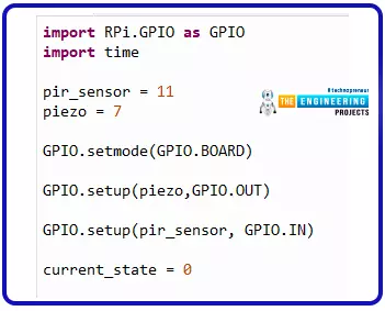
import RPi.GPIO as GPIO
import time
pir_sensor = 11
piezo = 7
GPIO.setmode(GPIO.BOARD)
GPIO.setup(piezo,GPIO.OUT)
GPIO.setup(pir_sensor, GPIO.IN)
current_state = 0
A while loop that never ends appears below. Due to the inherent permanence of the conditional statement, this loop can always be maintained. (You can still hit ctrl + c on the terminal to abort the script). To begin, we'll pause the script for 0.1 seconds. The next step is to retrieve the sensor's current state; if that state is 1 (for instance, the motion has been detected), the code within the if statement will be executed. If the value is not 1, we enter an infinite loop in which the sensor is repeatedly checked.
The if statement executes code that sets the piezo buzzer's output high, causing it to sound. This will occur for a split second before the script silences the buzzer. As soon as that timer expires, the if statement will leave, and the sensor will be rechecked after another five seconds. We have also used a try, except, finally, block with a nested outer block. Since stopping the script will require using the keyboard, we have included this. Finally, we must verify our script is tidy by calling GPIO.cleanup(). With the help of the try, except finally, coding construct, we can accomplish this.
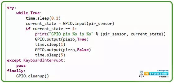
try:
while True:
time.sleep(0.1)
current_state = GPIO.input(pir_sensor)
if current_state == 1:
print("GPIO pin %s is %s" % (pir_sensor, current_state))
GPIO.output(piezo,True)
time.sleep(1)
GPIO.output(piezo,False)
time.sleep(5)
except KeyboardInterrupt:
pass
finally:
GPIO.cleanup()
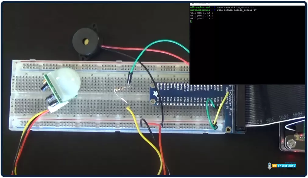
Running the Script
After you have completed all of your changes to the script, you may run it and see how it performs. Put the following command into your keyboard to accomplish this.

sudo python motion_sensor.py
The piezo buzzer should activate and make a noise if the PIR sensor detects motion in its field of view. If it doesn't, it's probably because you connected wires to the incorrect pins or because of a bug in the program. The Raspberry Pi's terminal will show an error message if it's a coding mistake.
Complete code
#!/usr/bin/env python
import RPi.GPIO as GPIO
import time
pir_sensor = 11
piezo = 7
GPIO.setmode(GPIO.BOARD)
GPIO.setup(piezo,GPIO.OUT)
GPIO.setup(pir_sensor, GPIO.IN)
current_state = 0
try:
while True:
time.sleep(0.1)
current_state = GPIO.input(pir_sensor)
if current_state == 1:
print("GPIO pin %s is %s" % (pir_sensor, current_state))
GPIO.output(piezo,True)
time.sleep(1)
GPIO.output(piezo,False)
time.sleep(5)
except KeyboardInterrupt:
pass
finally:
GPIO.cleanup()
Output
Quiz: Send data to your phone using an LTE modem
This section is meant to test your understanding of this programming series so far, so I am leaving it as some homework for you. Build the circuit and comment below what the output will be. I will give an idea of the circuit and Python code.
The LTE modem
Based on the success of GSM/EDGE and UMTS/HSPA, the Long-Term Evolution (LTE) standard was developed to ensure the continued development of wireless broadband communication. My LTE modem is a USB add-on for the Raspberry PI, giving it 3G or 4G (LTE) cellular data access. The modem is not used for cellular access in this project; instead, it is used to notify my phone of motion through text messages. The AT commands and serial connectivity allow me to command the modem and relay messages to my phone.

Connection
Step 1: Install the software
Begin by loading the required software onto your Raspberry Pi. Enter the terminal of the Raspberry Pi:

sudo apt install python3 python3-gpiozero python-serial -y
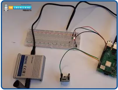
Step 2: Set up the modem
The TRM240 LTE modem requires a SIM card, which can be inserted here. To improve the modem's signal, attach the antenna to the top of the device.
Third, link the cellular modem to the Pi.
Plug the LTE modem into a free USB port on the Raspberry Pi and power it on. The /dev directory should now list four additional USB ports. Just type this into the terminal to verify:

ls /dev/ttyUSB*
These gadgets should now be visible to you.
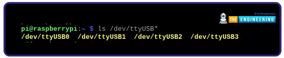
Sending AT commands to the device will be done through the ttyUSB2 port.
Fourth, link up the sensor with the Pi.
The sensor output pin should be connected to the 8-pin to the Raspberry Pi, and the VCC and GND pins should be connected to the appropriate pins on the Pi.
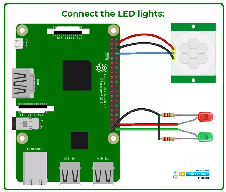
Connect the LED lights:
The cathode of the LED should be connected to a ground pin, the anode (longer leg) should be connected to a current-limiting resistor, and the other portion of the resistor should be connected to a GPIO pin to cause the indicator LEDs to illuminate when motion is detected. Input the green LED into the 40-pin connector and the red LED into the 38-pin connector on the board. This is a discretionary procedure. You can disable the LED sections in the sample code below if you don't want them to light up in response to the motion.
Launch the program below
from gpiozero import MotionSensor, LED
from time import sleep, time
from sys import exit
import serial
import threading
# Raspberry Pi GPIO pin config
sensor = MotionSensor(14)
green = LED(21)
red = LED(20)
# Modem configuration
device = '/dev/ttyUSB2'
message = ''
phone_number = ''
sms_timeout = 120 # min seconds between SMS messages
def setup():
port.close()
try:
port.open()
except serial.SerialException as e:
print('Error opening device: ' + str(e))
return False
# Turn off echo mode
port.write(b'ATE0 \r')
if not check_response('OK', 10):
print('Failed on ATE0')
return False
# Enter SMS text mode
port.write(b'AT+CMGF=1 \r')
if not check_response('OK', 6):
print('Failed on CMGF')
return False
# Switch character set to 'international reference alphabet'
# Note: this still doesn't support all characters
port.write(b'AT+CSCS="IRA" \r')
if not check_response('OK', 6):
print('Failed on CSCS')
return False
return True
def check_response(string, amount):
result = ''
try:
result = port.read(amount).decode()
except:
return False
if not string in result:
try:
# Write 'ESC' to exit SMS input mode, just in case
port.write(b'\x1B \r')
except:
return False
return string in result
def send_sms():
global currently_sending, last_msg_time
currently_sending = True
try:
port.write('AT+CMGS="{}" \r'.format(phone_number).encode())
if not check_response('>', 6):
print('Failed on CMGS')
currently_sending = False
return
# Write the message terminated by 'Ctrl+Z' or '1A' in ASCII
port.write('{}\x1A \r'.format(message).encode())
while True:
result = port.readline().decode()
if 'OK' in result:
print('> SMS sent successfully')
last_msg_time = time()
currently_sending = False
return
if 'ERROR' in result:
print('> Failed to send SMS [{}]'.format(result.rstrip()))
currently_sending = False
return
except:
# Initiate setup if the got while the program was running
setup()
currently_sending = False
def on_motion():
print('Motion detected!')
green.off()
red.on()
if time() - last_msg_time > sms_timeout and not currently_sending:
print('> Sending SMS...')
threading.Thread(target=send_sms).start()
def no_motion():
green.on()
red.off()
print('* Setting up...')
green.on()
red.on()
port = serial.Serial()
port.port = device
port.baudrate = 115200
port.timeout = 2
last_msg_time = 0
currently_sending = False
if not setup():
print('* Retrying...')
if not setup():
print('* Try restarting the modem')
exit(1)
print('* Do not move, setting up the PIR sensor...')
sensor.wait_for_no_motion()
print('* Device ready! ', end='', flush=True)
green.on()
red.off()
sensor.when_motion = on_motion
sensor.when_no_motion = no_motion
input('Press Enter or Ctrl+C to exit\n\n')
As mentioned above, I will not give the output for this program; instead, let me know if you were successful.
Conclusion
This is a basic introduction to the PIR sensor and merely scratches the surface of its potential uses. Simple things like a counter (which adds up as people, cars, or other objects pass by) can trigger far more complex actions, such as turning on a Pi camera or running a new script. I'm hoping you've learned a lot from this Pi 4 motion sensor tutorial and that you've been able to put together a beautiful circuit and make it work with some code. Feel free to leave a remark below with your views, questions, or complaints. In the subsequent tutorial, we'll learn how to interface an ultrasonic sensor with Raspberry Pi 4. Till then, take care. Have fun!!!