Control Servo Motor with Raspberry Pi 4 using Python


Hello friends, I hope you all are doing well. Welcome to the 11th tutorial of our Raspberry Pi programming course. In the previous chapter, we have seen how to regulate the speed of a Stepper motor with Raspberry Pi 4. Today, we'll work on the servo motor and will control it with RPi4. So, let's get started:
Components Required:
We will need the following components to control Servo Motor with Raspberry Pi 4:
- Raspberry Pi 4.
- Servo Motor.
- Male-to-female jumper wires.
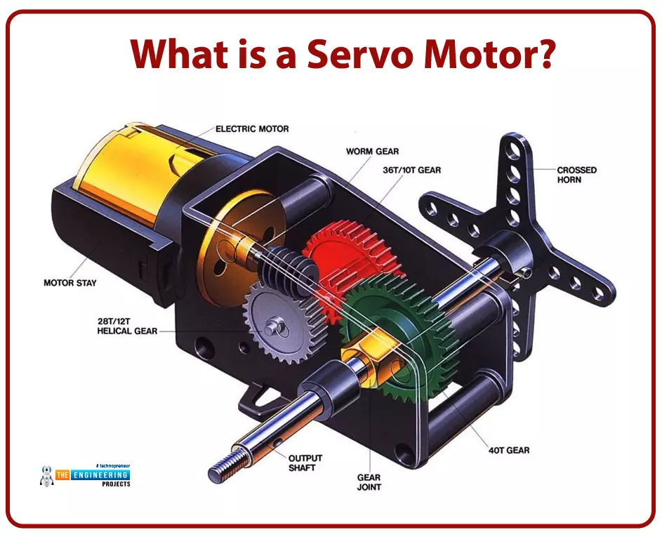
What is a servo motor?
-
A Servo Motor is a simple DC motor with a position feedback Control System and a gearbox.
- A Servo Motor's primary advantage is its ability to maintain its shaft's angular position at any desired angle i.e. if we want to keep our shaft at 67 degrees, we can easily achieve that with a servo motor.
- In most cases, a servo motor's sweep area is 180 degrees or 90 degrees on either side.
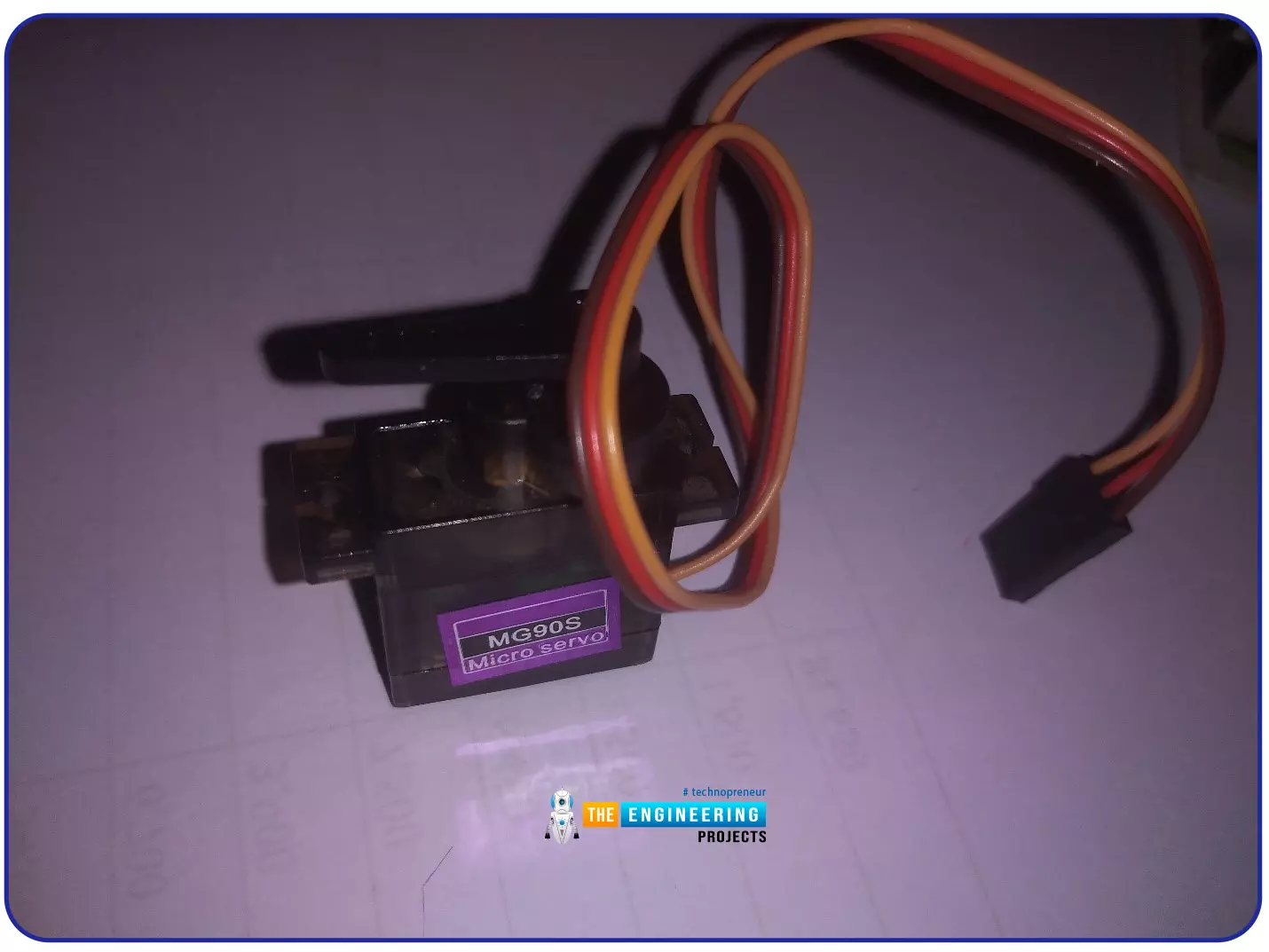
- Servo Motors come in a variety of styles and sizes. Tower Pro SG90 and Tower Pro MG90S are two of the most popular Servo Motors.
- The gearbox in the Servo motor could be metallic or plastic.
- We will use SG90 Servo Motor in today's project and it has a plastic gearbox, shown in the below figure:
The Tower Pro SG90 Servo Motor has 3 wires in total, which are:
- Signal(Orange or Yellow)
- VCC (Red)
- GND(black)
Vcc and GND pins of the servo motor should be connected to the
power supply. The Servo Motor's Signal Wire should be connected to the Controller's GPIO Pin.
Types of Servo Motors
There are three wires in a standard servo motor: one for power control, one for ground, and one for neutral. Their intended purpose determines the size and shape of these motors.
There are unlimited possibilities in Robotics where we can use Raspberry Pi to control servo motors.
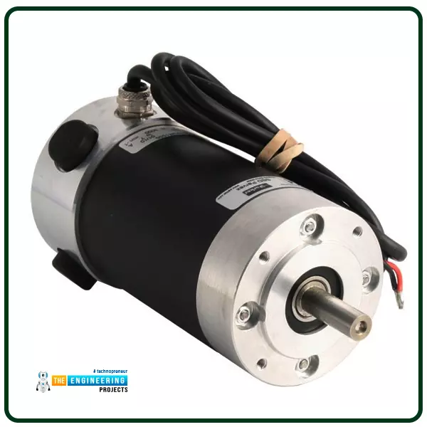
DC Servo Motors
DC servo motors usually have separate DC sources for the stator and armature windings. The armature current and the field current can be controlled to get the desired result.
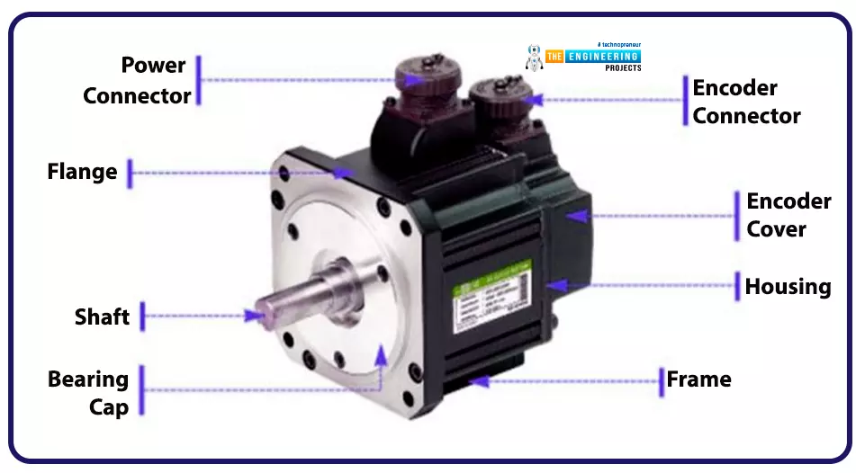
AC Servo Motors
An AC servo motor, which incorporates an encoder, is employed for closed-loop control systems. This motor may be precisely positioned and regulated to meet the application's needs. Better bearings and higher tolerances are common in these motors, and higher voltages are sometimes used in simple designs to boost torque. When it comes to robotics, CNC machines, and other automated systems, servo motors are preferred because of their accuracy and precision.
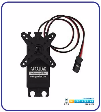
Positional Rotation Servo Motor
It is the most commonly used servo motor and has a rotation of approximately 180 degrees. To keep the rotation sensor safe, it has physical brakes built into the gear mechanism. Many of these popular servos are used in radio-controlled water, radio-controlled automobiles, airplanes, robotics, toys, and many more applications.
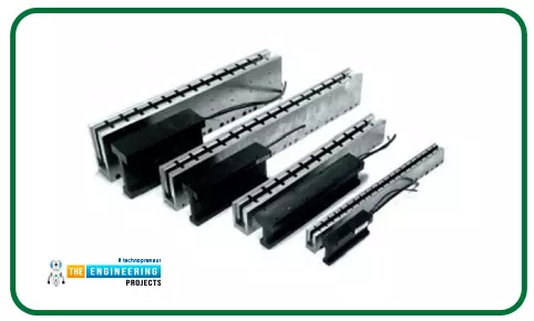
Linear Servo
Additional gears transform the servo motor output from circular motion to back-and-forth motion.
Servo Motor Working Principle
A servo mechanism consists of three main components i.e.
- DC Motor.
- Feedback.
- Control Electronics.
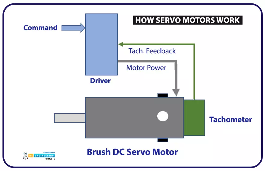
The servo motor uses a permanent magnet DC motor with an inbuilt tachometer to calculate the output voltage. The electronics drive provides motors with electrical power in response to tachometer feedback voltages. After setting a commanded speed using a closed velocity loop, the driver's circuitry compares the tachometer feedback voltage to the goal speed. The velocity loop monitors the tachometer feedback and the commanded velocity while the driver modulates the power in the motor.
A sophisticated servo motor system has multiple integrated loops configured to optimal performance for the most precise motion control. For current, velocity, and location, the system uses feedback loops with high precision. To adjust parameters in real-time, each loop notifies the next and checks the feedback elements.
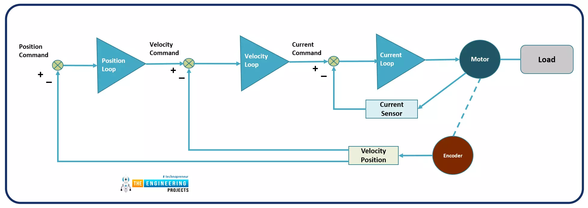
The current loop, also known as the torque loop, is the foundation for all other loops. An electric motor's acceleration or thrust is determined by the relationship between current and torque (or force, in the case of a linear motor). A current sensor is a device that measures the amount of current flowing through the motor and communicates this information to the user. Control electronics frequently receive proportional signals via analog or digital techniques. Ordered signals are subtracted from this signal. The servo motor needs to run at the specified current for an extended period to keep the loop intact. It will then update at sub-second intervals until it reaches the desired current.
Similarly, the velocity loop works with a voltage proportional to velocity in the same method. At low velocities, the current loop receives a command from the velocity loop to increase voltage.
The velocity loop is fed a velocity command from a PLC or motion controller that supplies the required current for acceleration and deceleration of the motor. The servo mechanism is controlled precisely and smoothly by the three loops working together in perfect harmony.
It doesn't matter if it's brushed or brushless, rotatory, or linear. The servo system receives feedback from various sensors, i.e. potentiometers, encoders, linear transducers etc. This system's capabilities are rounded out by an electronic control system that verifies feedback data and command references to make sure the servo motor is performing as instructed. Multi-axis milling centers use brushless motors and motion control systems more complex than those used in recreational applications.
How to Control a Servo Motor?
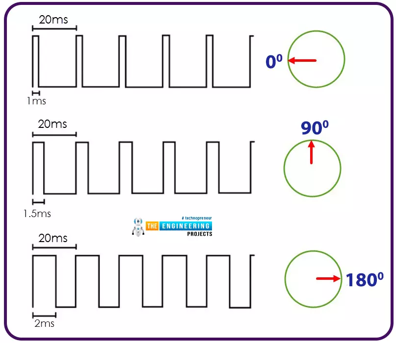
Pulse Width Modulation is required to operate a servo motor. The pulse's width or length controls the servo motor's shaft position when using the PWM approach.
There is a defined frequency for the PWM signal, determined by the type of Servo Motor being used. The PWM Frequency of our SG90 and MG90S Servo Motors is 50Hz.

A pulse width signal of one millisecond (one-thousandth of a second) sets the servo's position to the LEFT. This post has a duty cycle of 0.5 percent.
As with pulse widths of 1.5 and 2 microseconds, the servo is set to MIDDLE (7.5% duty cycle) and FAR RIGHT with a duty cycle of 10%.
Circuit Diagram of Raspberry Pi Servo Motor Interface:
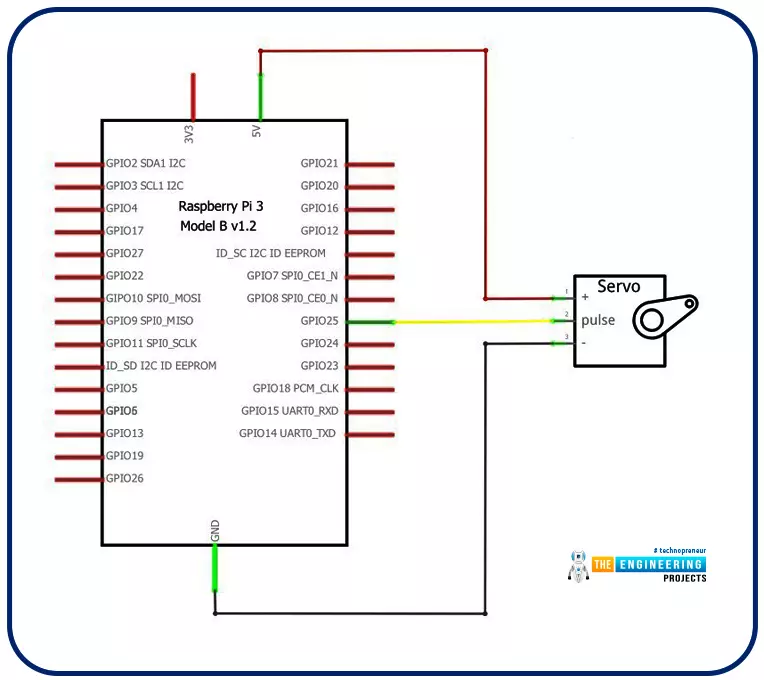
- Here is a diagram of the Raspberry Pi Servo Motor Interface's circuit:
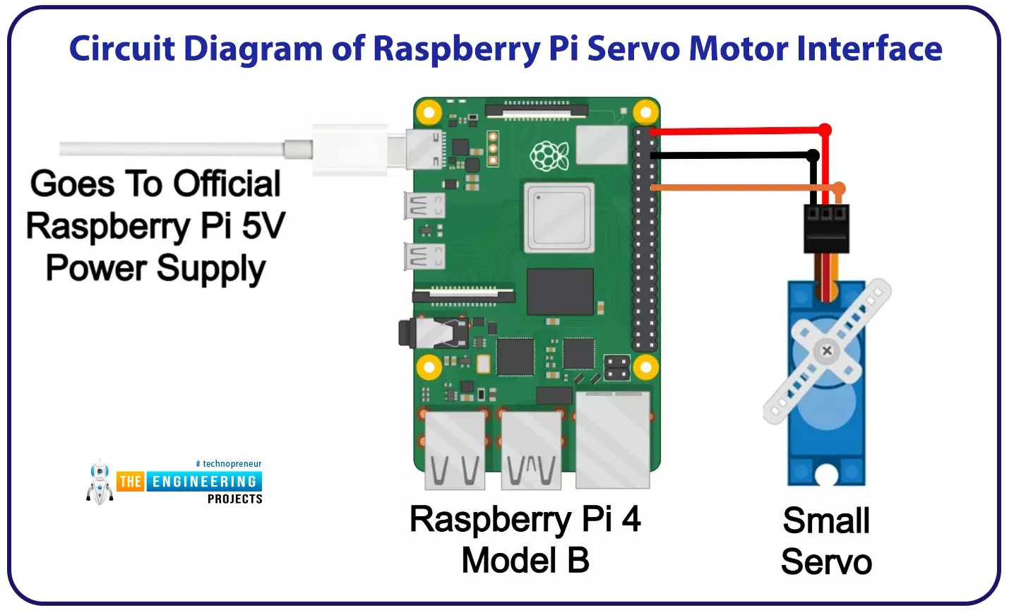
- As you can see in the above figure, a single PWM Pin(GPIO25) of the Raspberry Pi 4 is used to control the Servo position.
- Servo Vcc is connected to 5V, while the GND is connected to the Ground of Raspberry Pi 4.
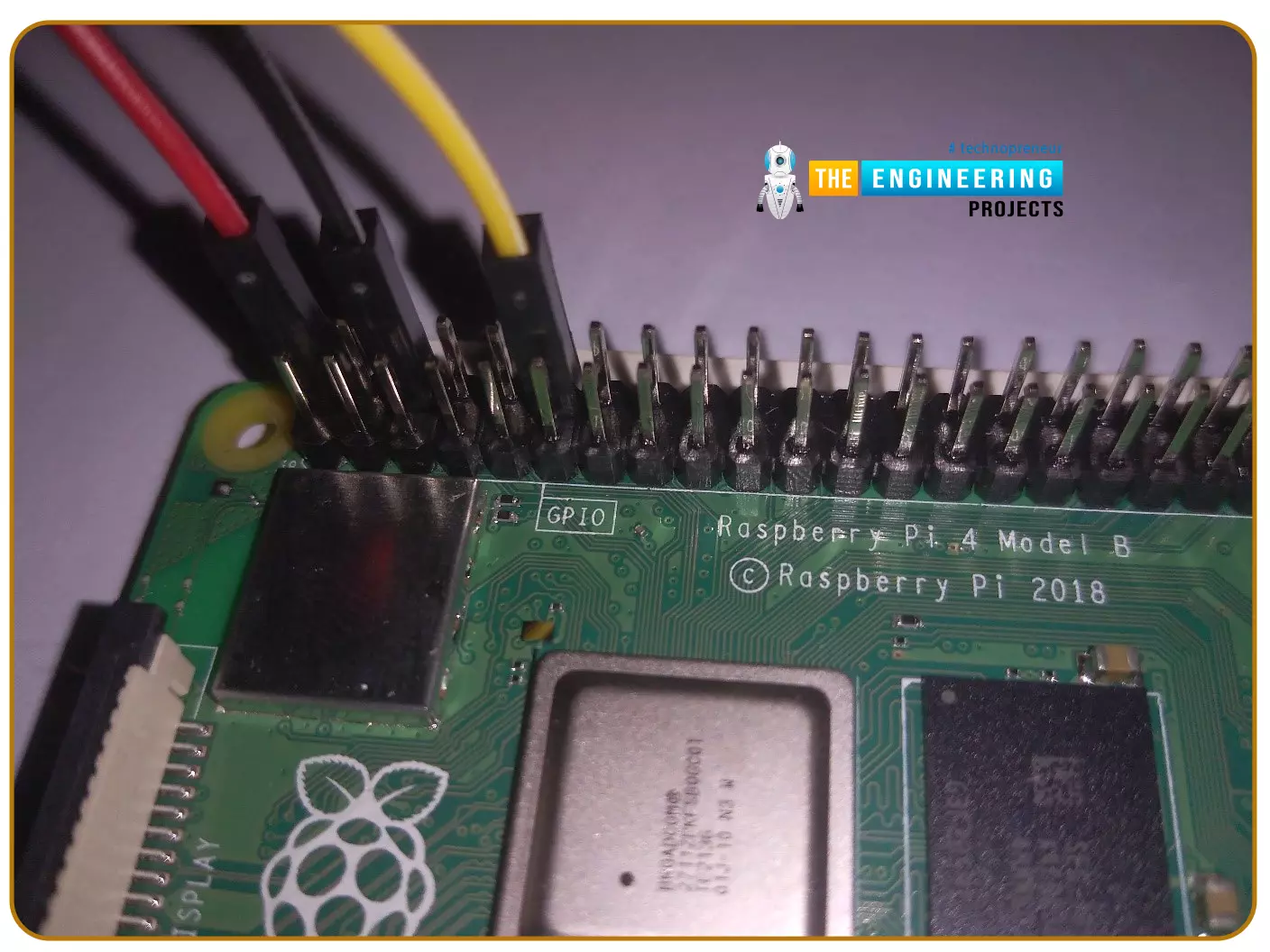
- Here's a wiring diagram that can help you visualize the connections better:
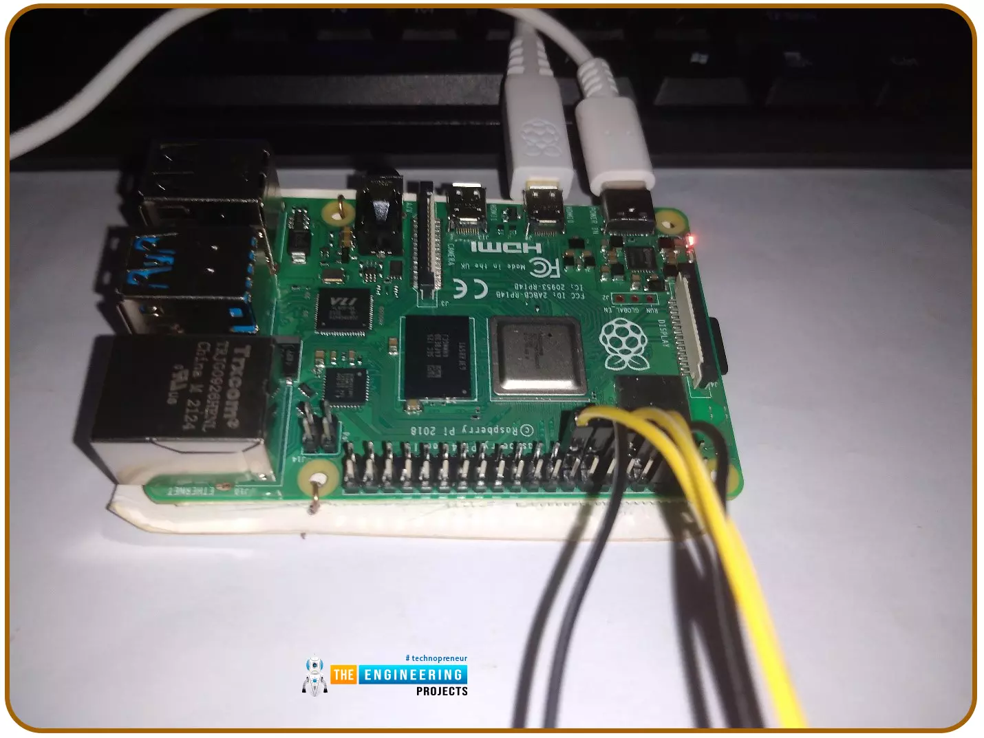
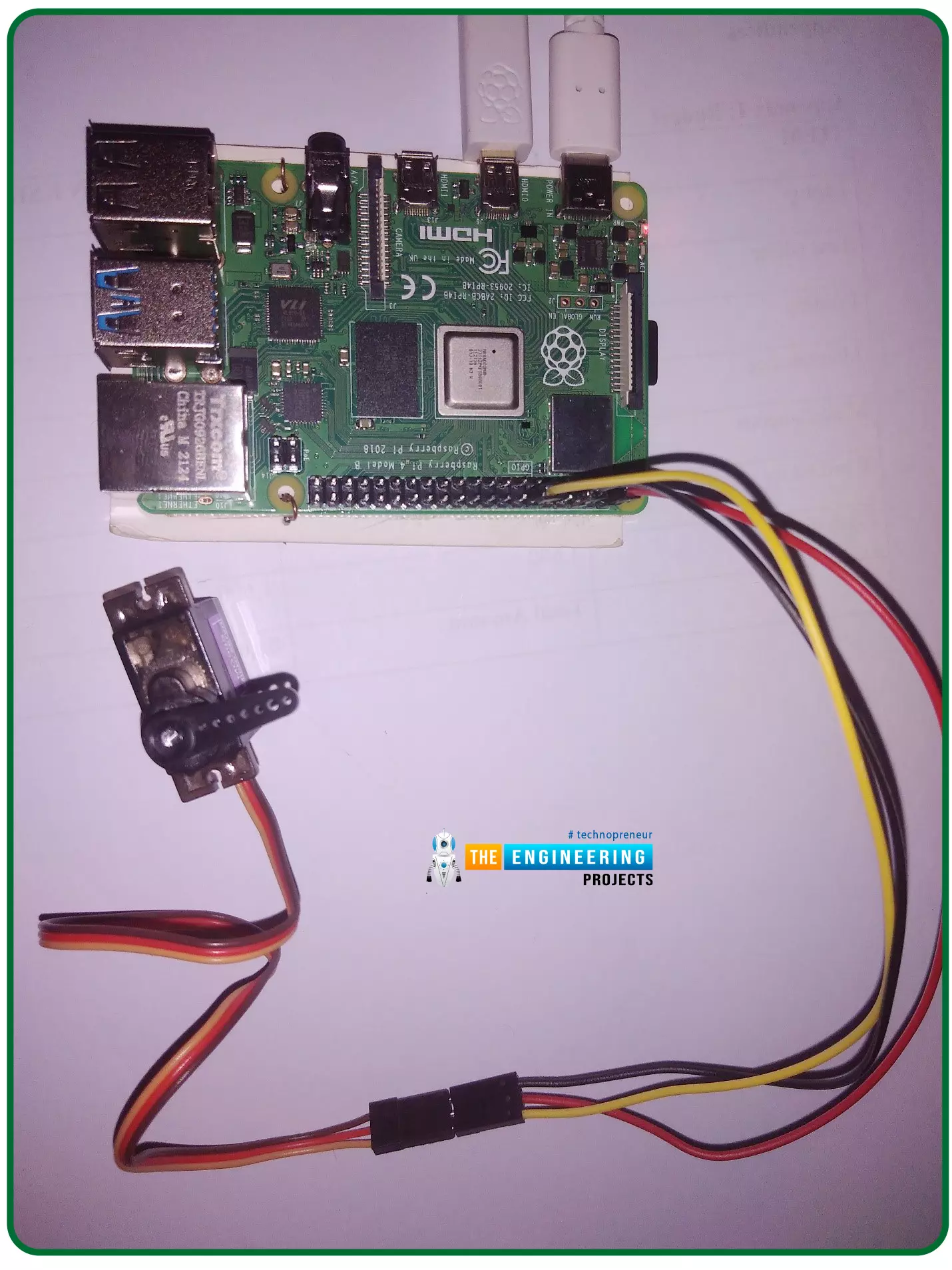
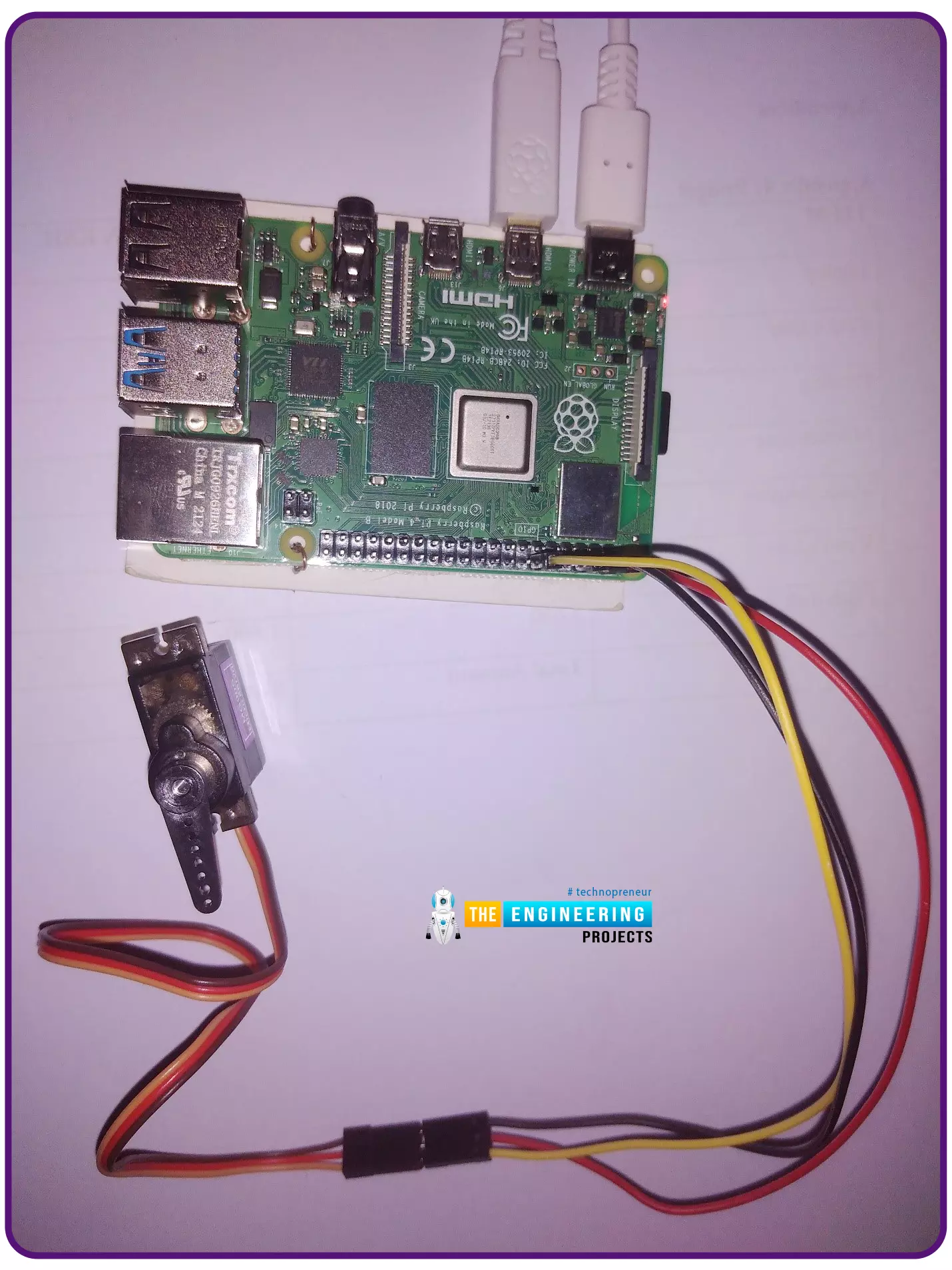
- Here's our hardware setup of Servo Motor with Raspberry Pi 4:
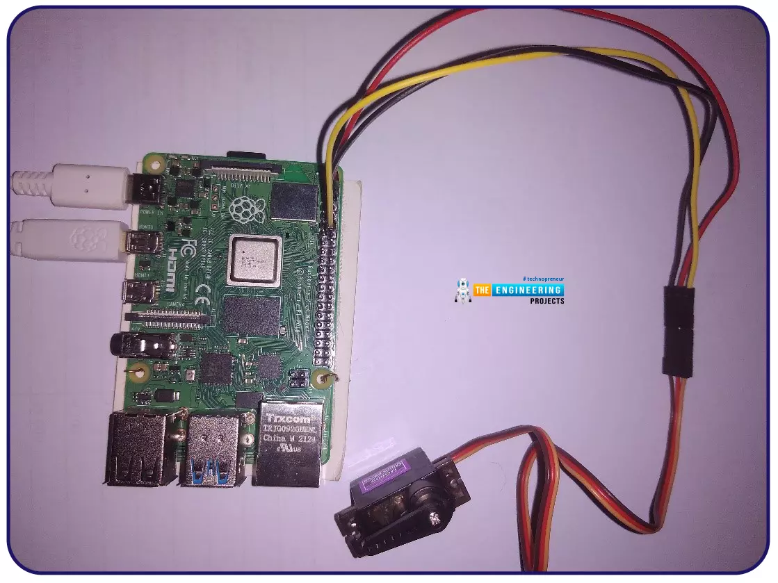
- The motor has three wires: red, brown, and orange, which you should pay attention to. The color red denotes positive(Vcc), while the color brown denotes negative(GND).
- Pulse-width modulation control signals are sent through the orange wires. So, we have connected 3 wires with the pins of Raspberry Pi 4.
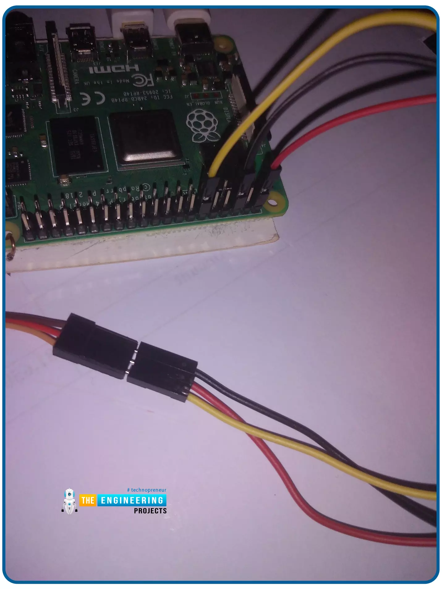
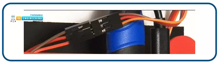
- We have used jumper cables, as depicted in the image below:
Python Code for Servo Control with Raspberry Pi 4
Now let's design the Python code for Servo Motor Control using Raspberry Pi. We'll be using our favorite code editor, Thonny, so get it up and running on your Raspberry Pi:
Importing libraries
- Importing the necessary libraries is the first step. Time and the GPIO of the Raspberry Pi in this scenario.

GPIO board mode
- When the GPIO numbering mode is changed, it will be consistent with the board's numbering system.

Configuring PWM GPIO
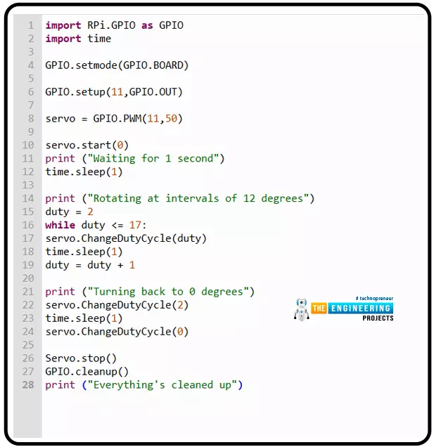
- Now, set Pin11 to be the output:

- After that, we'll create a variable. I used PWM to name my servo's Pin11. 50 is the pulse frequency at Pin11, while 11 is the PIN.

Start PWM

Rotate the Servo shaft
Variable duties are defined and assigned random values, such as 2. When counting our intervals, it serves as the starting point.
After that, we'll run a for loop to find all the duty values between 2 and 17. Given the range of 2 to 17 as an interval, The motor will move the shaft if duty is increased by one every time the shaft moves. After every one-second interval, the shaft rotates 12 degrees to the right until it reaches 180 degrees.

Let's turn the shaft back
- Changing the duty cycle is all it takes to reset the shaft to 0 degrees.

Clean up
- The following code snippet is used to clean the pins.

Final Servo Output
- When all of the code in the example above is run, the motor shaft will be rotated 180 degrees back and forth.

You can experiment with multiple motors to see how much fun this can be. This project's complete source code can be seen below:
Working on the setup
When it comes time to put the concept into action, we'll take advantage of Raspberry Pi's PWM functionality. If you've been following along, you know that the Servo Motor position changes depending on the PWM signal from the Raspberry Pi.
To achieve a sweeping effect from the Servo Motor, we need to alter the PWM signal's Duty Cycle between 5% and 10%, corresponding to the extreme left and right positions.
If you look at the code, you'll see that the duty cycle steadily increases from 5% to 10%, with a 0.5 percent increase at each stage. The reversal will commence as soon as it hits 10%.
Applications of servo motors
Many applications can benefit from regulating the angle of rotation of the Servo Motor via the Raspberry Pi, such as:
Cameras, telescopes, and antennas
It is impossible to find a radio signal, take pictures of a galaxy billions of light-years away, or photograph a live subject without using a servo motor.
Elevator
It's all about safety while designing and implementing transportation networks for buildings. Servo motors are extensively used in elevators in some of the world's highest buildings to carry passengers safely and smoothly.
Robotics
Robotics is a hot topic, and their practical applications are growing at an ever-increasing rate. Servo motors, which are compact, powerful, and precise due to their changing size and force density, are the most widely utilized in robotics. Using robots to control the detonation of bombs, autonomous firefighter trucks, or even the joints in robot arms is all possible.
Industrial production
To eliminate the risk of human error and speed up production, manufacturers are creating robotic alternatives. Another robot example is the pick and place robot, which can move items from one side of an industrial building to the other. Servo motors are commonly utilized when mobility or rotations could be hazardous.
Precision and power are critical features of servo motors, which are used in bending and cutting metal sheets and high-speed milling machines. Servo motors are commonly employed in the spinning sections of conveyor systems in various industries, such as the food and beverage industry.
Conclusion
Congratulations! You have made it to the end of this tutorial. We have seen how PWM is used to control a servo motor. A variety of servo motor designs and real-world applications have also been demonstrated and their application in real life. In the next tutorial, we will learn how to interface an LDR Sensor with Raspberry Pi 4. Thanks for reading. Have a good day.