Interface 4x4 Keypad with Raspberry Pi 4


Hello friends, I hope you all are doing well. Welcome to the next tutorial of our Raspberry Pi 4 programming course. In the previous lecture, we interfaced LCD 16x2 with Raspberry Pi 4. Today, we will interface a keypad 4x4 to Raspberry Pi 4. In embedded projects, a keypad is used to get user input i.e. calculator, ATM keypad etc. Different types of Keypads are available i.e. 4x4, 4x3 etc.
So, let's get started:
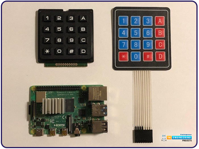
Components Required
We will need the following components in our today's project:
- Raspberry Pi 4
- Keypad 4x4
- Breadboard
- Connecting Wires
Keypad 4x4
- A keypad is a collection of push buttons, arranged in a matrix form.
- Keypad 4x3 means the keypad has 4 rows and 3 columns and 12 buttons in total.
- A 4 by 4 keypad membrane has 8 pins in total, its first 4 pins devoted to its rows and its second 4 pins dedicated to its columns.
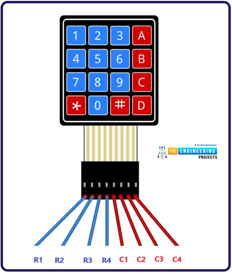
- To reduce the need for pins, they are laid out in a matrix pattern, and a membrane switch is used internally.
- The small size, low cost, and easy-to-install features make it a more affordable alternative to touchscreens.
Any microcontroller's GPIO can be used to power a keypad; thus, there's no need for an additional power supply. A pulse must be sent from the Raspberry Pi to all four rows of the Keypad to determine which button was pressed. If the user pushes a button associated with the currently pulled high line, the column associated with that line will be pushed high.
The pressed button can be identified by deciphering the sequence of rows and columns. When a user hits the B button in the second row of the fourth column, Pi 4 will send a pulse to the second line and then see which of the four columns was pulled high to determine which button was pressed.
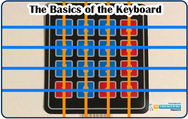
Keypad Working
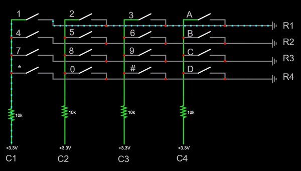
The graphic above depicts the reasoning behind how we will interpret the keys pressed on the Keypad. As indicated, the membrane switches are laid out in a matrix.
- In a normal condition, the four columns (C1, C2, C3, and C4) remain HIGH(internally pull-up), while all the rows (R1, R2, R3, and R4) are provided with Ground(GND) one after the other.
- The columns are constantly monitored by the microcontroller, to check for a LOW signal.
- If the key "1" is pressed, the column (C1) would get "shorted" to the row (R1), resulting in a "LOW" signal at C1, which will be captured by the microcontroller.
Following the iteration of each row, columns are set back to High.
I hope you understood the working of the keypad. Now let's interface our Keypad with RPi4:
Keyboard & Raspberry Pi 4 Circuit Diagram
We don't need to provide any power pins to these keypads. Simple, connect the Keypad's eight data pins to the RPi4's GPIO pins:
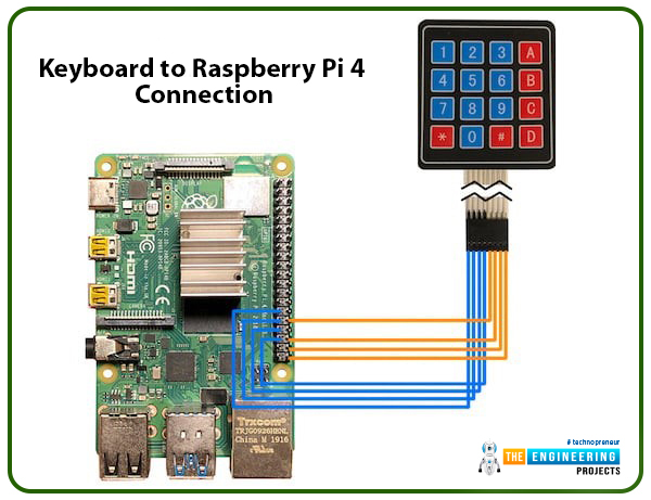
Like the image up top, I used a monochromatic color palette. The rows are denoted by the blue connections, while the orange ones show the columns.
Keyboard & Raspberry Pi 4 Python Code
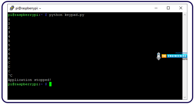
After connecting the pins as described above, the next step is to run a test program that outputs the Keypad's button push to the Raspberry Pi 4's console.
# GPIO setup and imports omitted
def readLine(line, characters):
GPIO.output(line, GPIO.HIGH)
if(GPIO.input(C1) == 1):
print(characters[0])
if(GPIO.input(C2) == 1):
print(characters[1])
if(GPIO.input(C3) == 1):
print(characters[2])
if(GPIO.input(C4) == 1):
print(characters[3])
GPIO.output(line, GPIO.LOW)
try:
while True:
readLine(L1, ["1","2","3","A"])
readLine(L2, ["4","5","6","B"])
readLine(L3, ["7","8","9","C"])
readLine(L4, ["*","0","#","D"])
time.sleep(0.1)
except KeyboardInterrupt:
print("\nApplication stopped!")
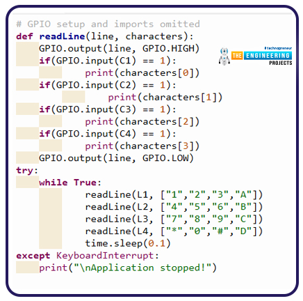
In the above code, we have a readLine command, which reads the rows one by one and checks if the button is pressed. If any button is pressed, the digit will appear in the Pi Console. The approach also requires a dictionary of button-to-symbol correspondences.
You can think of this code as a basic demo. You can't even press and hold a button and have it register that. Each pulse it transmits on the output line will identify a new keystroke.
Example 2
Below is a program that can accurately identify individual key presses and use them to activate a basic code lock.
Complete code
import RPi.GPIO as GPIO
import time
L1 = 5
L2 = 6
L3 = 13
L4 = 19
C1 = 12
C2 = 16
C3 = 20
C4 = 21
keypadPressed = -1
secretCode = "4789"
input = ""
GPIO.setwarnings(False)
GPIO.setmode(GPIO.BCM)
GPIO.setup(L1, GPIO.OUT)
GPIO.setup(L2, GPIO.OUT)
GPIO.setup(L3, GPIO.OUT)
GPIO.setup(L4, GPIO.OUT)
GPIO.setup(C1, GPIO.IN, pull_up_down=GPIO.PUD_DOWN)
GPIO.setup(C2, GPIO.IN, pull_up_down=GPIO.PUD_DOWN)
GPIO.setup(C3, GPIO.IN, pull_up_down=GPIO.PUD_DOWN)
GPIO.setup(C4, GPIO.IN, pull_up_down=GPIO.PUD_DOWN)
def keypadCallback(channel):
global keypadPressed
if keypadPressed == -1:
keypadPressed = channel
GPIO.add_event_detect(C1, GPIO.RISING, callback=keypadCallback)
GPIO.add_event_detect(C2, GPIO.RISING, callback=keypadCallback)
GPIO.add_event_detect(C3, GPIO.RISING, callback=keypadCallback)
GPIO.add_event_detect(C4, GPIO.RISING, callback=keypadCallback)
def setAllLines(state):
GPIO.output(L1, state)
GPIO.output(L2, state)
GPIO.output(L3, state)
GPIO.output(L4, state)
def checkSpecialKeys():
global input
pressed = False
GPIO.output(L3, GPIO.HIGH)
if (GPIO.input(C4) == 1):
print("Input reset!");
pressed = True
GPIO.output(L3, GPIO.LOW)
GPIO.output(L1, GPIO.HIGH)
if (not pressed and GPIO.input(C4) == 1):
if input == secretCode:
print("Code correct!")
# TODO: Unlock a door, turn a light on, etc.
else:
print("Incorrect code!")
pressed = True
GPIO.output(L3, GPIO.LOW)
if pressed:
input = ""
return pressed
def readLine(line, characters):
global input
# We have to send a pulse on each line to
# detect button presses
GPIO.output(line, GPIO.HIGH)
if(GPIO.input(C1) == 1):
input = input + characters[0]
if(GPIO.input(C2) == 1):
input = input + characters[1]
if(GPIO.input(C3) == 1):
input = input + characters[2]
if(GPIO.input(C4) == 1):
input = input + characters[3]
GPIO.output(line, GPIO.LOW)
try:
while True:
if keypadPressed != -1:
setAllLines(GPIO.HIGH)
if GPIO.input(keypadPressed) == 0:
keypadPressed = -1
else:
time.sleep(0.1)
else:
if not checkSpecialKeys():
readLine(L1, ["1","2","3","A"])
readLine(L2, ["4","5","6","B"])
readLine(L3, ["7","8","9","C"])
readLine(L4, ["*","0","#","D"])
time.sleep(0.1)
else:
time.sleep(0.1)
except KeyboardInterrupt:
print("\nApplication stopped!")
Programming using interrupt
You may have noticed that the "while" loop we used above is polling for each row of our Keypad. This is OK for a basic project, but it may not function properly if your project requires interaction with a more complex system i.e. robotics.
The other option is to utilize a library that relies on "interrupts," allowing us to assign a different event controller to each key on our Keypad. The Pi 4 would be alerted(interrupted) by a click on the membrane switch.
The following code will walk you through the process step by step. You can see that the code that iteratively scans each row no longer uses polling while loop. You will receive feedback whenever the button is pressed or released by pressing the number one on your Keypad.
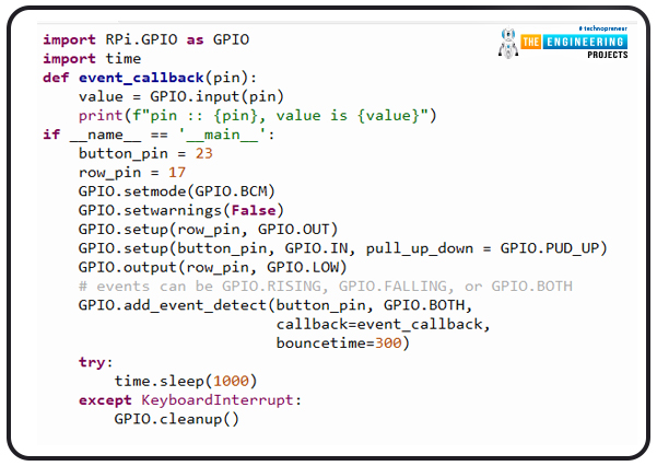
import RPi.GPIO as GPIO
import time
def event_callback(pin):
value = GPIO.input(pin)
print(f"pin :: {pin}, value is {value}")
if __name__ == '__main__':
button_pin = 23
row_pin = 17
GPIO.setmode(GPIO.BCM)
GPIO.setwarnings(False)
GPIO.setup(row_pin, GPIO.OUT)
GPIO.setup(button_pin, GPIO.IN, pull_up_down = GPIO.PUD_UP)
GPIO.output(row_pin, GPIO.LOW)
# events can be GPIO.RISING, GPIO.FALLING, or GPIO.BOTH
GPIO.add_event_detect(button_pin, GPIO.BOTH,
callback=event_callback,
bouncetime=300)
try:
time.sleep(1000)
except KeyboardInterrupt:
GPIO.cleanup()
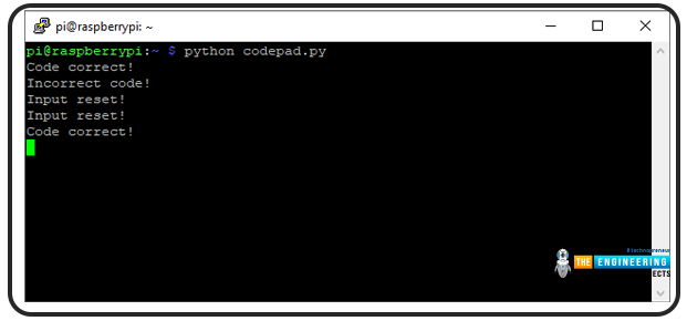
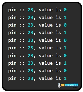
Please enter the following into your terminal to execute this code. When I press the switch, its value drops to zero, and when I let go of it, it jumps to one.
Programming using pad4pi interrupt package
With this knowledge in hand, I searched for a library that provides a similar capability. I came across pad4pi in the pypi repository, which does the trick—type in the following command to set it up on your Raspberry Pi.
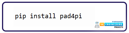
pip install pad4pi
This is the test script I eventually came up with afterward. Check out the source and sample test scripts on the library's main page.
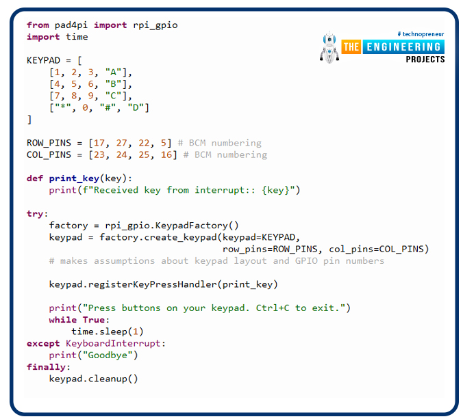
#!/usr/bin/python
from pad4pi import rpi_gpio
import time
KEYPAD = [
[1, 2, 3, "A"],
[4, 5, 6, "B"],
[7, 8, 9, "C"],
["*", 0, "#", "D"]
]
ROW_PINS = [17, 27, 22, 5] # BCM numbering
COL_PINS = [23, 24, 25, 16] # BCM numbering
def print_key(key):
print(f"Received key from interrupt:: {key}")
try:
factory = rpi_gpio.KeypadFactory()
keypad = factory.create_keypad(keypad=KEYPAD,row_pins=ROW_PINS, col_pins=COL_PINS) # makes assumptions about keypad layout and GPIO pin numbers
Keypad.registerKeyPressHandler(print_key)
print("Press buttons on your keypad. Ctrl+C to exit.")
while True:
time.sleep(1)
except KeyboardInterrupt:
print("Goodbye")
finally:
keypad.cleanup()
Import required modules on lines 3 and 4.
GPIO pins and rows are defined on lines 6-14.
A toggle activates the callback feature on the Keypad, located at lines 16–18.
Initialization script for pad4pi and callback handler registration lines 19–31.
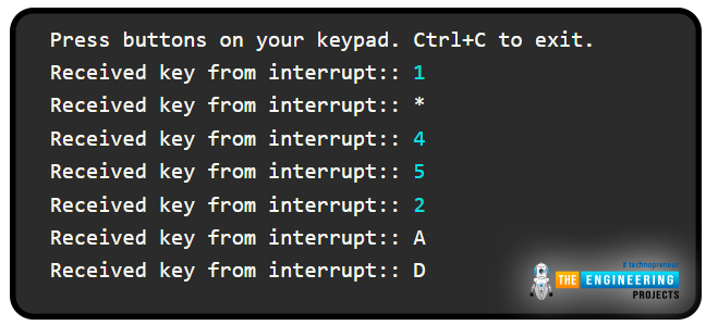
Here is the output of this program.
Strategies for Creating a 4x4 Keypad Circuit
Keyboard Debouncing
The hardware diagrams call for almost no more parts, and the firmware is based on a straightforward technique that any newbie can quickly grasp. Pay attention to these two details, if you really care about giving people a pleasant time while using the Keypad. These images demonstrate the use of a capacitor for debouncing in hardware.
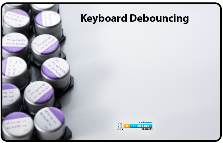
The extra pulse that a button may send to the controller but it is already released, is one of the most typical problems with a mechanical keypad. The button's spring mechanism is responsible for this behavior. As a result, it's common for the firmware to save conflicting settings for the same button. Debouncing is used to prevent the Keypad from being read incorrectly. This can be accomplished mechanically by installing a capacitor to block the after-button-release micro pulses.
Firmware writers can opt to use software debouncing as well. The firmware now filters out the infinitesimally brief pulses from samples that can never be activated by human contact instead of examining each individual triggering input. It's also useful for keeping the Keypad traces free of noisy signals that could couple through the background electricity. To avoid such problems, correct design principles must be established.
Conclusion
This article has shown how a basic 4x4 keypad can be connected to Raspberry Pi 4 to give users a quick and easy way to enter data and communicate with their own Raspberry Pi-based applications. A small number of digital I/O pins can power the Keypad. Since the key matrix only comprises push buttons, the Raspberry Pi is not required to provide power to the device.
Every Keypad's internal matrix row receives pulses from the Raspberry Pi 4. When a user presses a button, it closes a contact that links a specific row to a particular column. To determine which key the user has pressed, the Raspberry Pi monitors the column signals and responds accordingly. Any language compatible with a Pi 4 can accomplish this method.
So, that was all for today. In the next tutorial, we will discuss How to get a PWM Singal in Raspberry Pi 4. Stay tuned!!!