Interfacing a Light Sensor (LDR) with Raspberry Pi 4


Hello friends, I hope you all are doing great. Today, we are going to start Section-III of our Raspberry Pi 4 Programming Course. In this section, we will interface different Embedded Sensors with Raspberry Pi 4. Today's our first lecture in Section-III, so I am going to interface a simple LDR sensor with RPi4.
So, let's get started:
Components Required:
The following items are required to finish this Raspberry Pi photoresistor module guide. You don't need a breadboard to accomplish this, but having one would be helpful.
- Raspberry pi 4
- Breadboard
- Photoresistor LDR
- Jumper wires
- 1uF Capacitor
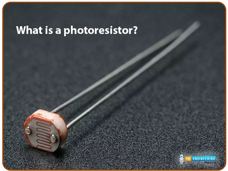
What is a photoresist?
It is a common practice to employ photoresistors to determine the presence or absence of visible light or to quantify the amount of light hitting a particular surface. Their resistance is exceptionally high in the dark, reaching up to 1M ohm, but when subjected to light, the LDR sensor's resistance reduces rapidly, often to only a few ohms. Light-dependent resistors (LDRs) are nonlinear devices whose sensitivity shifts depending on the incident wavelength of light. To protect their ecosystems, some nations have outlawed the use of lead and cadmium in LDRs.
By analyzing the electromagnetic radiation in the "Infrared", "Visible" and "Ultraviolet" regions of the electromagnetic spectrum, Light Sensors can produce an output signal indicative of the brightness of the surrounding light. A passive device called a light sensor transforms this "light energy," which can come from either the visible or infrared regions of the spectrum, into an electrical signal. Because they convert the energy of light (photons) into a usable form of electricity, light sensors are also referred to as photoelectric devices or photo sensors (electrons).
There are two primary types of photoelectric devices: those that produce electricity when exposed to light (photovoltaics, photoemissive, etc.) and those that modify their electrical properties when exposed to light (photoresistors, photoconductors, etc.).
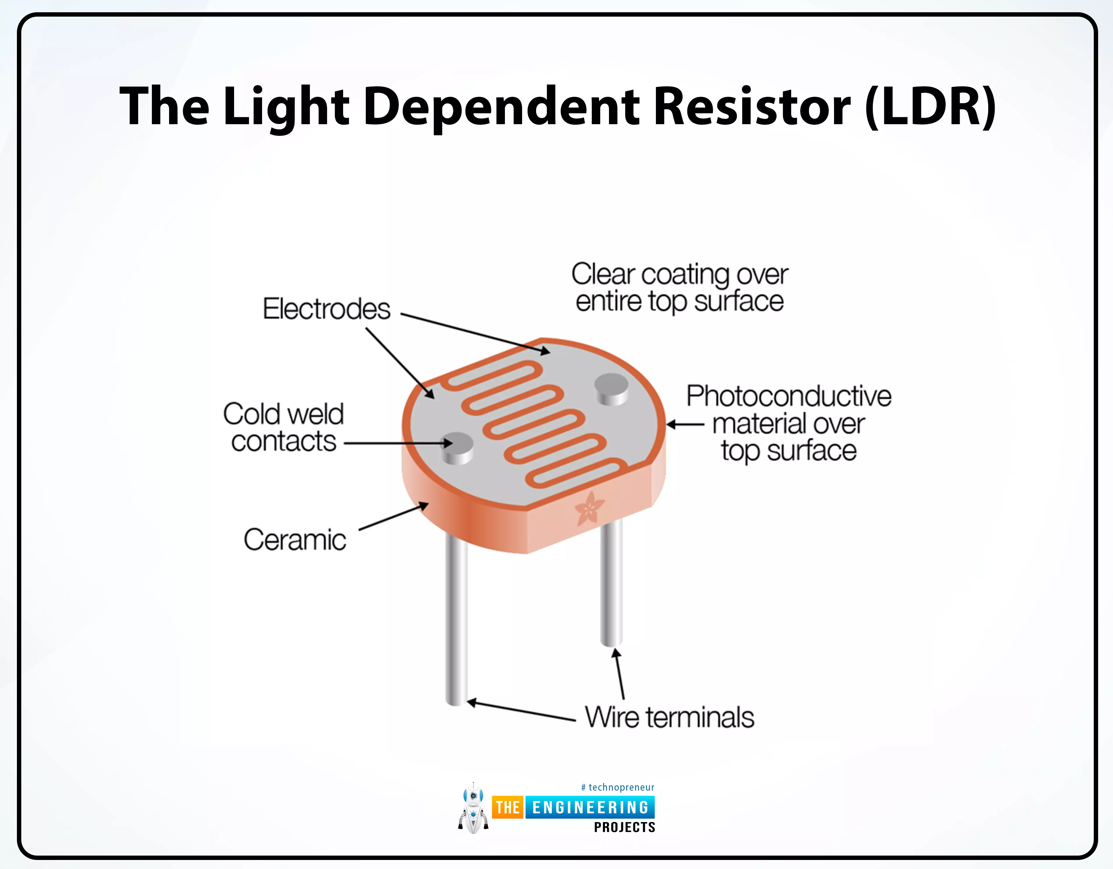
Light Dependent Resistor(LDR)
The light-dependent resistor (LDR) sensor is used to detect the intensity of light in the surroundings. The LDR is a device constructed from a sensitive semiconductor material i.e. cadmium sulfide, which undergoes a dramatic shift in electrical resistance when exposed to light, going from several 1000 Ohms in the dark to just a few Ohms, when illuminated.
Most photoresistive light sensors employ cadmium sulfide(CdS). However, other semiconductor substrate materials like lead sulfide (PbS), lead selenide (PbSe), and indium antimony (InSb) can detect light intensity as well. Since cadmium sulfide has a spectral response curve similar to the human eye's and can be modulated with a handheld torch, it is utilized to create photoconductive cells. The peak wavelength at which it is most sensitive is typically between 560-600nm (nanometers), making it part of the visible spectrum.
The Light Dependent Resistor Cell

The ORP12 cadmium sulfide photoconductive cell is the most widely used photoresistive light sensor. This photosensitive resistor's spectral response is concentrated around 610 nm in the yellow-to-orange part of the spectrum. When the cell is in the dark, its resistance is extremely high at around 10M's, but it drops to about 100's when illuminated (lit resistance). As the resistive path zigzags across the ceramic substrate, the dark resistance increases and the dark current drops. Because of its low price and wide range of possible applications, the CdS photocell is frequently used in auto-dimming systems, light- and dark-sensing controls for streetlights, and photographic exposure meters.
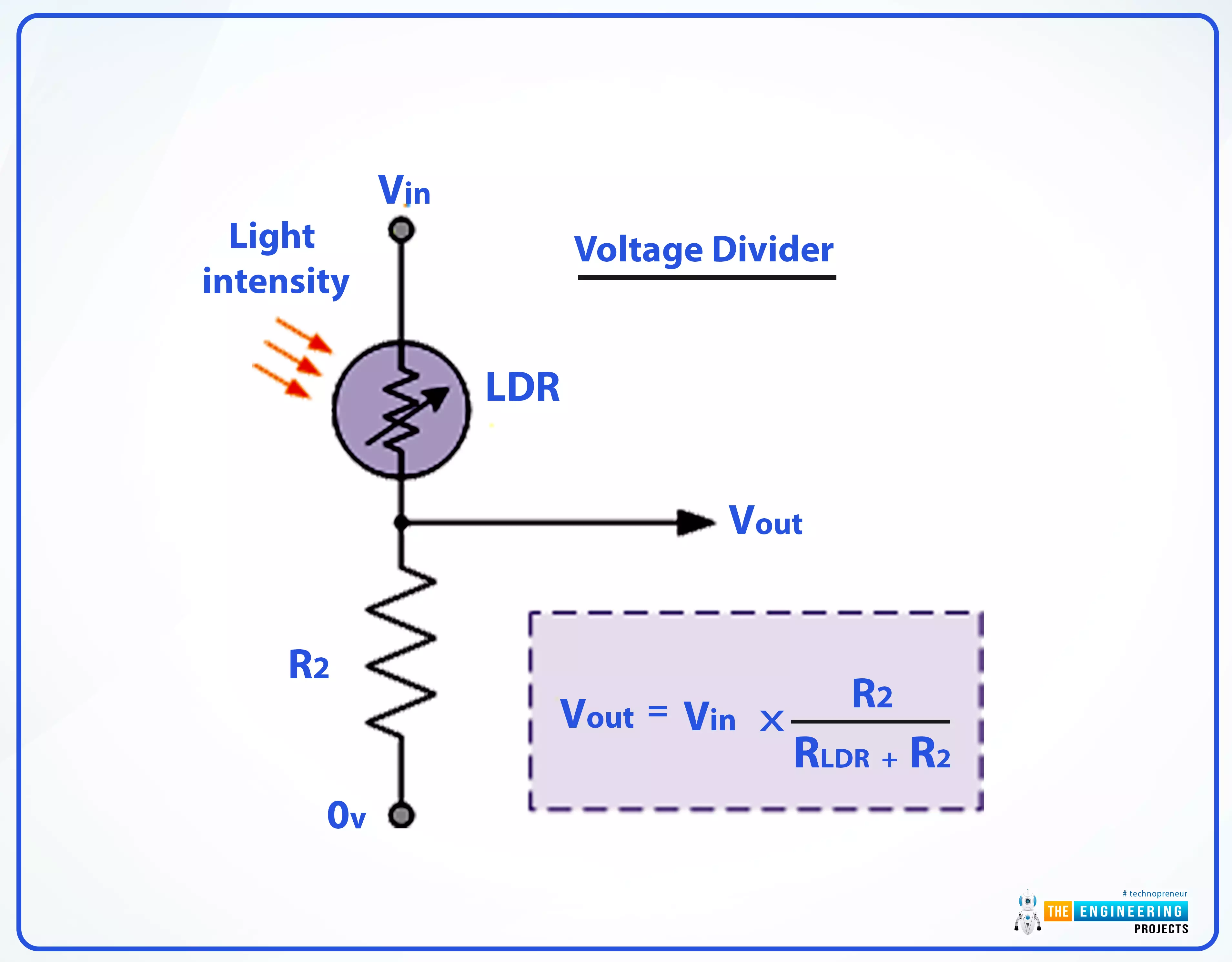
Below is an illustration of how a light-dependent resistor can be used as a light-sensitive switch.
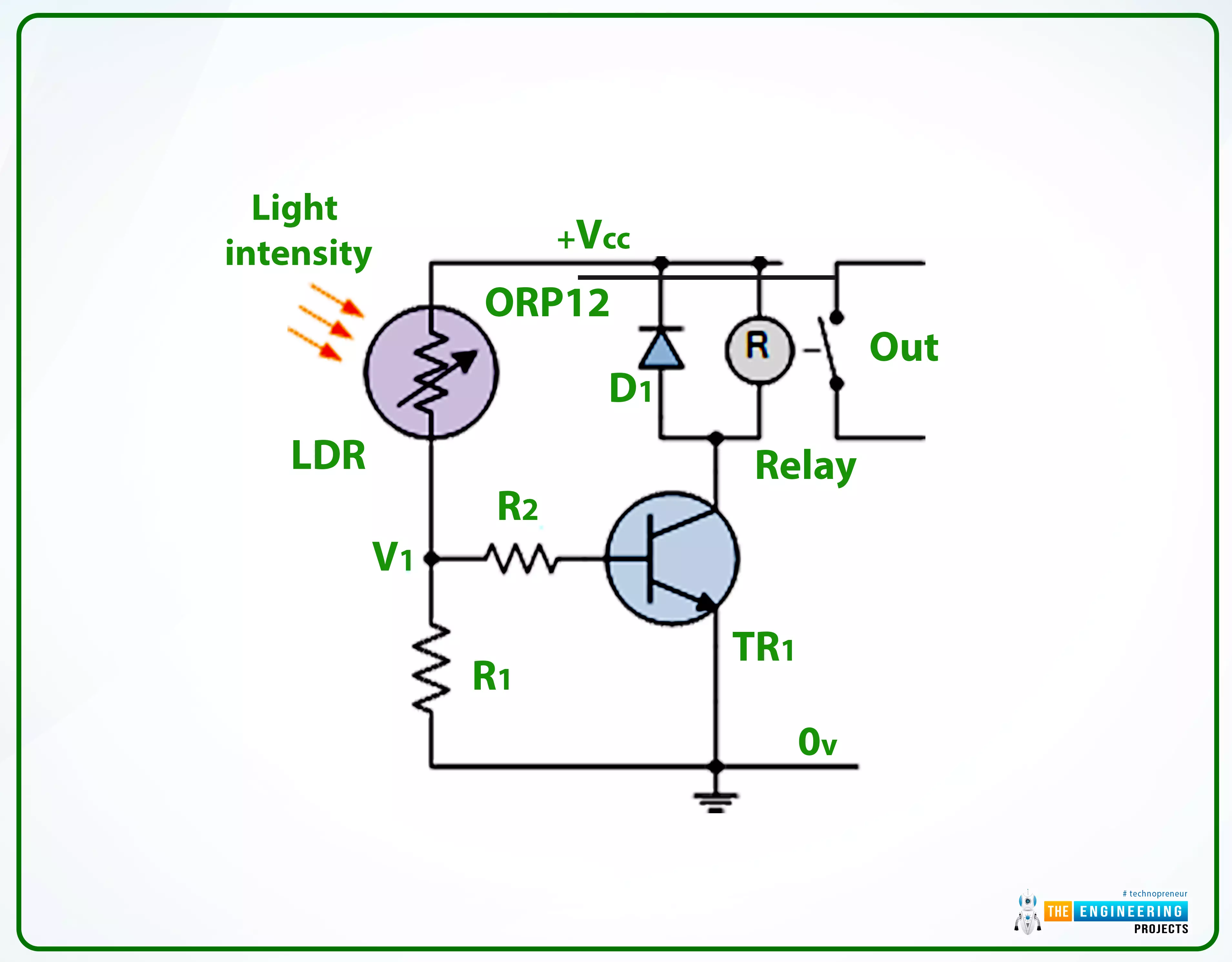
This simple circuit for detecting light consists of a relay activated by exposure to sunlight. The photoresistor LDR and the resistor R1 make up a potential divider circuit. In the absence of light, the LDR's resistance rises into the Megaohm (M) range, and as a result, the transistor TR1 receives zero base bias, turning the relay off. The LDR's resistance drops in response to more light, elevating the base bias voltage at V1. When the base bias voltage of transistor TR1 reaches a certain threshold, as defined by the resistance R1 in a potential divider network, the transistor turns "ON," activating the relay, which controls some external circuitry. With a return to darkness, the LDR's resistance rises, reducing the transistor's base voltage and turning "OFF" the transistor and relay at a predetermined level of illumination established by the potentiometer circuit.
Changing the relay's "ON" or "OFF" point to a custom brightness is as simple as swapping out the fixed resistor R1 for a potentiometer VR1. The switching end of a simple circuit like the one depicted above may need to be more consistent owing to fluctuations in temperature or supply voltage. Using the LDR in a "Wheatstone Bridge" configuration and substituting an Operational Amplifier for the transistor makes it simple to construct a light-activated circuit with increased sensitivity.
Circuit Diagram of LDR with RPi4
To build the circuit of the LDR sensor with RPi4, follow these instructions. You can also refer to the
below
circuit diagram:
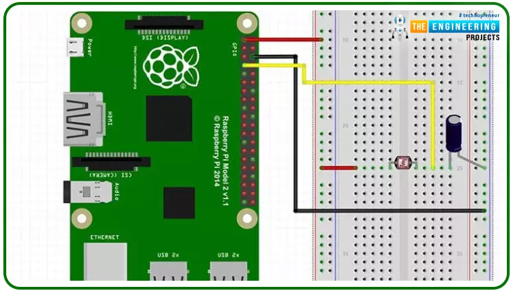
- To begin, attach Pin1 of RPi4 to the breadboard's positive rail.
- Then, attach pin 6 of RPi4 to the breadboard's ground rail.
- Next, place the LDR sensor on the board with one end connected to the power supply's positive rail.
- Connect the opposite end of the LDR sensor to the Pin4 of RPi4 using a jumper wire.
Now is the time to start writing Python code for LDR:
Python Code for LDR Sensor with Raspberry Pi 4
This project's code is simple and will let us know whether it's bright outside, partly cloudy, or overcast. The lack of analog inputs on the Pi is the primary limitation of this device. So far, we have only worked on the digital modules, but here we need an analog pin to get a reliable reading of the input resistance variation. So, we'll count how long the capacitor takes to recharge and then set the pin high. This is a quick but unreliable way to gauge the ambient light level.
Here I will quickly go over the code for the LDR sensor with Raspberry Pi. As a first step toward establishing a connection with the GPIO pins, we import the necessary GPIO package. The time package is also imported, allowing us to schedule script inactivity.
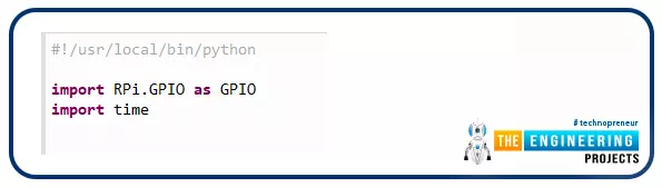
#!/user/local/bin/python
import RPi.GPIO as GPIO
import time
Next, we change the GPIO modes to GPIO.BOARD so that the pins used in the script match the hardware. One variable only needs to be set because there is just one input/output pin. If you use a specific GPIO pin, assign its number to this variable.
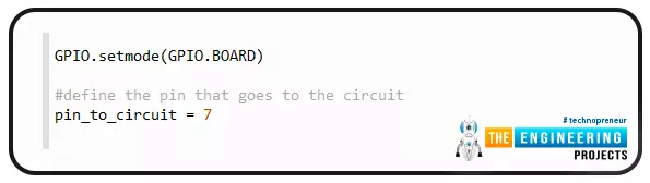
GPIO.setmode(GPIO.BOARD)
#define the pin that goes to the circuit
pin_to_circuit = 7
The following function we'll look at is RC time, and it takes a single input: the circuit's PIN. In this code, we set the value of a variable named count to zero, and then, when the pin is set to high, we return that number. Our pin is then configured as an output before being brought low. Then we let the program rest for ten milliseconds. When this is done, the pin is converted to an input, and a while loop is started. In this loop, the capacitor is charged until it is around 3/4 full, at which point the pin swings high. Once the pin is set to high, we send the count back to the primary method. This number can be used to toggle an LED, trigger an action, or be stored to compile data on brightness fluctuations.
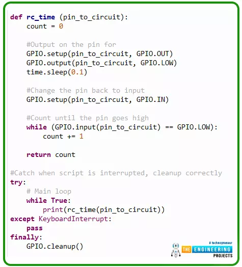
def rc_time (pin_to_circuit):
count = 0
#Output on the pin for
GPIO.setup(pin_to_circuit, GPIO.OUT)
GPIO.output(pin_to_circuit, GPIO.LOW)
time.sleep(0.1)
#Change the pin back to the input
GPIO.setup(pin_to_circuit, GPIO.IN)
#Count until the pin goes high
while (GPIO.input(pin_to_circuit) == GPIO.LOW):
count += 1
return count
#Catch when the script is interrupted, clean it up correctly
Try:
# Main loop
while True:
print(rc_time(pin_to_circuit))
except KeyboardInterrupt:
pass
finally:
GPIO.cleanup()
Executing the Program on Your Pi 4
Even though this is a trivial procedure, I'll run through it fast so you can get it up and work on your Pi without any hiccups. I am employing Raspbian, the operating system used in all the guides here. Read my Raspbian installation instructions if you need assistance. In most circumstances, all the necessary software will already be installed. Using git clone, the source code can be downloaded. Here's a command that will carry out your request.
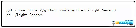
git clone https://github.com/pimylifeup/Light_Sensor/
cd ./Light_Sensor
The code can also be copied and pasted, but only into a Python script. When working with Python code, my preferred text editor is nano.
sudo nano light_sensor.py
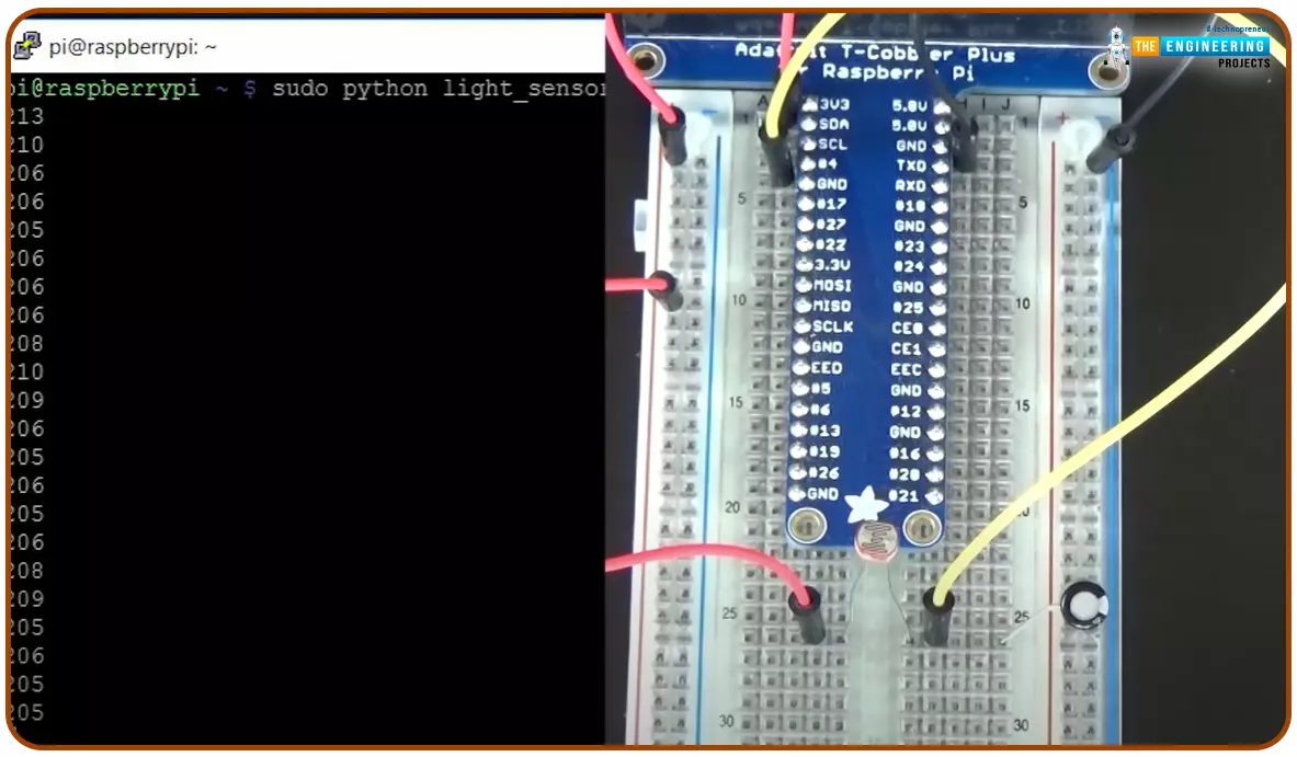
To save your changes and leave the file, press CTRL+X then Y. Finally, the following command will execute the code.

sudo python light_sensor.py
Hopefully, you've fixed the script and are now getting readings that accurately reflect the light levels on the sensor. Be bold about posting a comment if you need help.
Output
LDR Sensor Applications
A light sensor can be implemented in a variety of circuitry contexts. Some that sprang to mind when I was penning this guide are as follows:
An LDR can detect the onset of daylight, allowing for the activation of an alarm to rouse you from sleep. With a reliable program and sensor, you may set the alarm to increase in volume as daylight fades gradually. One way to keep tabs on your garden is to use a light sensor to measure how much sun each section of your garden is getting. This could be helpful knowledge if you're planting anything that needs a lot of sun or vice versa. Using the Room Monitor, you can ensure the lights in a particular room are switched off whenever no one is there. This might be set up to send you an alert if the light is found in an unexpected place.
Conclusion
This fantastic sensor has a wide variety of applications. However, if you need something more precise than a photocell, consider the Adafruit dynamic range sensor. You had no trouble installing this light sensor on your Raspberry Pi. Please comment below if you have any issues or suggestions or think I need to include something. In the next section, we'll see how to interface a Soil Moisture Sensor with Raspberry Pi 4. Till then, take care. Have fun!!!