Interface a 4-Channel Relay with Raspberry Pi 4


We learned in the previous tutorial how to connect a joystick to a Raspberry Pi 4 using an mcp3008 and an op-amp IC, the LM324A. For each of the interface methods we studied, we created a python script allowing us to interact with the circuit. This tutorial will show you how to connect a 4-channel relay module with a Raspberry Pi to carry out switching.
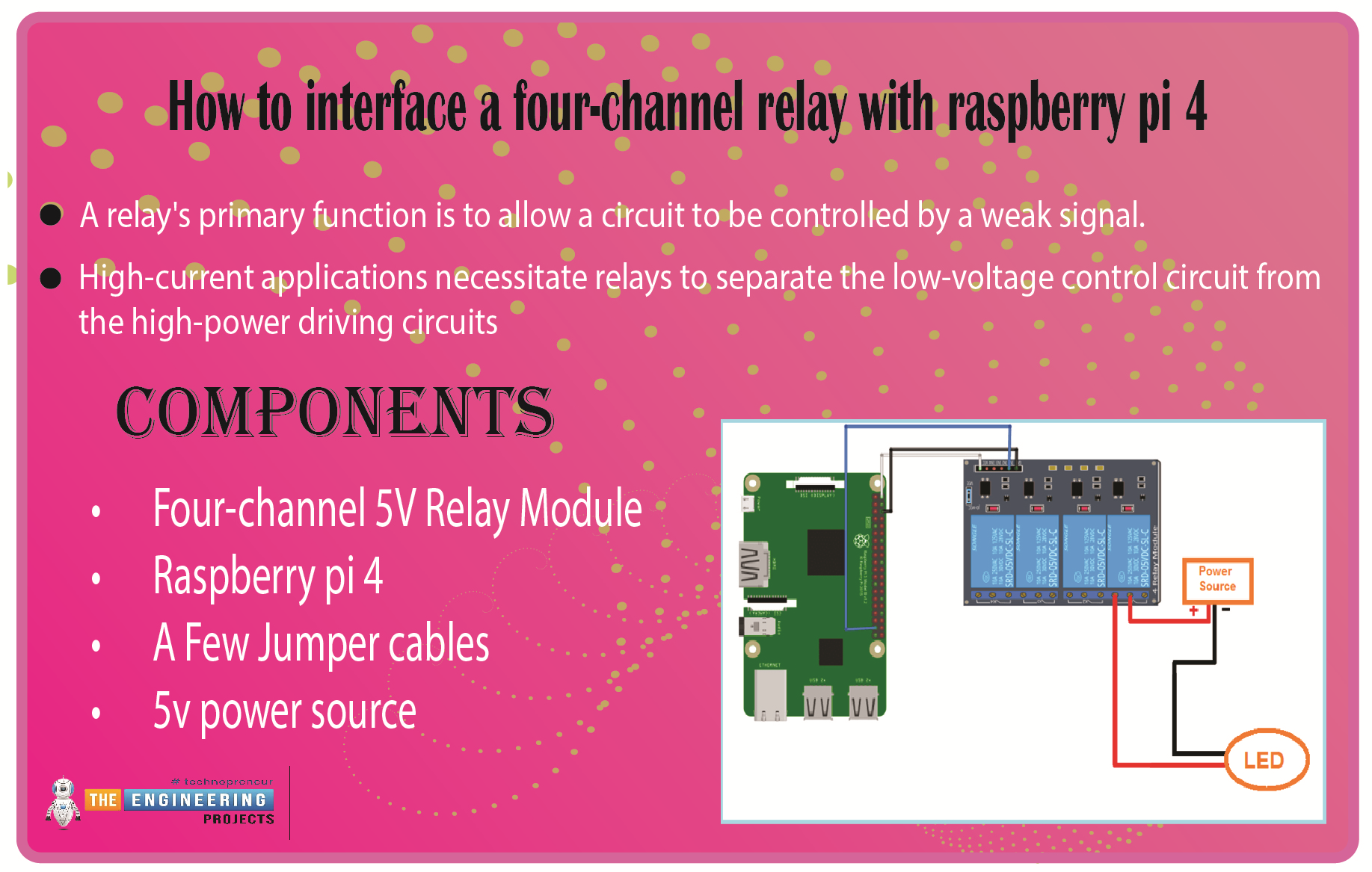
A relay's primary function is to allow a circuit to be controlled by a weak signal. High-current applications necessitate relays to separate the low-voltage control circuit from the high-power driving circuits. Because of this, understanding it is crucial for those interested in industrial or household automation.
If you've been tinkering with a raspberry pi for a while, consider the various ways in which you might put it to use.
So let’s dive in!
Components
Four-channel 5V Relay Module
Raspberry pi 4
A Few Jumper cables
5v power source
The raspberry pi has real-world uses, such as remotely turning a device on or off over the internet, sensors, or a mobile app communicating with the pi via Bluetooth. If we can master this, we will open up a world of possibilities.
Raspberry Pi as a Device Switch
Anybody who has experimented with a Raspberry Pi knows it has a GPIO.
The 40-pin general-purpose input/output (GPIO) connector is great for connecting various output devices. Since it is a digital computer, Raspberry Pi's GPIO pins can provide logic outputs. Logic 0 and 1 are the terms used to describe these two possible results from a logic circuit. If you write a program to make a Raspberry Pi pin write logic zero, you'll get a real-world GND potential. Likewise, when logic 1 is written on the Raspberry Pi pin, +3.3V is produced.
Logic 0 (gnd) and logic 1 (+3.3v) may be generated on any Raspberry Pi output pin with some programming. However, the output voltage is too low to power any real-world equipment. A maximum of 20 mA can be drawn from the output pin, as the 3.3V generated is currently limited. This only means that we can connect an LED straight to a Raspberry Pi gpio pin. In addition to the DC motor, no other output device can be connected directly to the raspberry pi's pin. Because of this, a different method is required when connecting an AC device.
How do relays work?
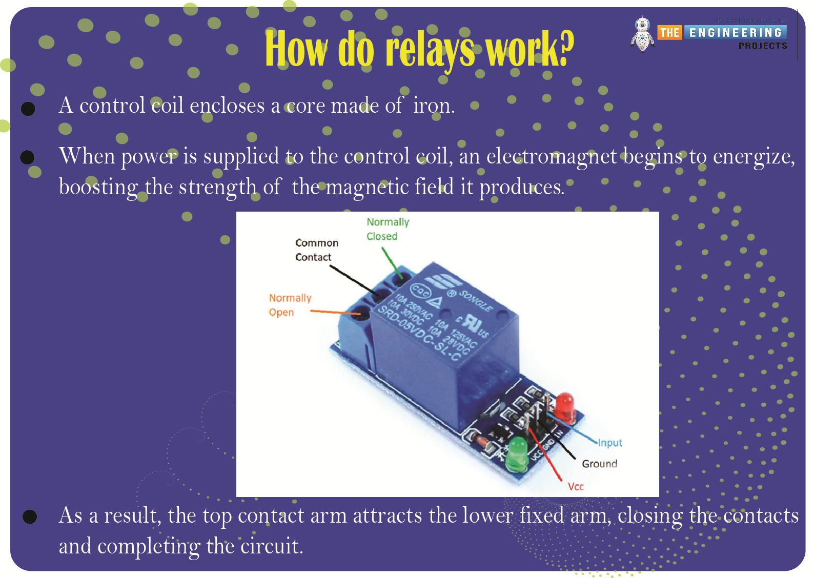
This image is a cross-sectional diagram of a relay's inner workings. A control coil encloses a core made of iron. When power is supplied to the control coil, an electromagnet begins to energize, boosting the strength of the magnetic field it produces. As a result, the top contact arm attracts the lower fixed arm, closing the contacts and completing the circuit. However, if the relay were de-energized before the connections were closed, the contacts would travel the opposite way, creating an open circuit. When the coil current is shut off, the spring will return the movable armature to its original position.
The operation of a relay is identical to that of a switch. This also means that the same principle applies. When a relay is used, one or even more poles are flipped. Each pole has two primary contact directions. They have NO contact, commonly known as the Normal Open Contact configuration. Connecting with someone is another name for this action. On activation, the relay completes the circuit. Once the relay is deactivated, the circuit is broken.
NC contact is short for normally closed contact. This is synonymous with the term "break contact." In contrast to "NO contact," communication will occur. By switching on the relay, the circuit is broken. As soon as the relay is turned off, the circuit is complete.
A relay's COM contact is shared by the normally closed (NC) and normally open (NO) contacts.
An example of a relay module with two channels is displayed here. As its name implies, a two-channel relay module consists of a circuit with two independent relays built in. This enables the simultaneous manipulation of two distinct gadgets. It follows that the greater the available channels, the more gadgets we can link together.
Let's connect the Pi 4 to the 2-channel relay now. With its four corresponding pins, the 2-channel relay may communicate with a Raspberry Pi. VCC, GND, IN1, and IN2 are the inputs. Current input higher than 30 mA and an input voltage of 5 V is required to power the relay module. As a result of this glaring current shortfall, we must rely on an external power source. Here, we'll employ the widely used MB102 Breadboard Power Supply, an external power supply board. If you're curious about this power source and why we decided to use it, there are some helpful links below. A 3.3 V Relay is what you'll need to operate with Relays without an external power supply.
The relay module's VCC pin must be connected to the power supply's 5 V pin. Then Join the Raspberry Pi 4's ground pin (GND) to the power supply's ground pin (GND). The next step is to attach a jumper wire between the power supply's second GND port and the Raspberry Pi's second GND port. As a result, the ground pin on the Pi 4, the relay switch, and the power source are now all connected. Last but not least, connect a push button to GPIO 2 to activate the relay. Let's connect a few high-powered gadgets across the relay's output now. As seen in the circuit schematic, a CFL is connected to the NC and COM ports.
Using a Relay as a Switching Circuit
As was previously mentioned, the RPi is a computer with an output range of only +3.3v to 0v. We need a dedicated electronic switching circuit to link any real-world device to the Raspberry Pi and enable it to switch. Assume throughout this lesson that you want to control an electrical lamp using raspberry pi. A switching circuit is required because we cannot wire the light bulb directly to the raspberry pi. There must be a switching circuit, such as a relay, to turn on and off AC appliances.
The following graphic depicts the internal structure of a relay.
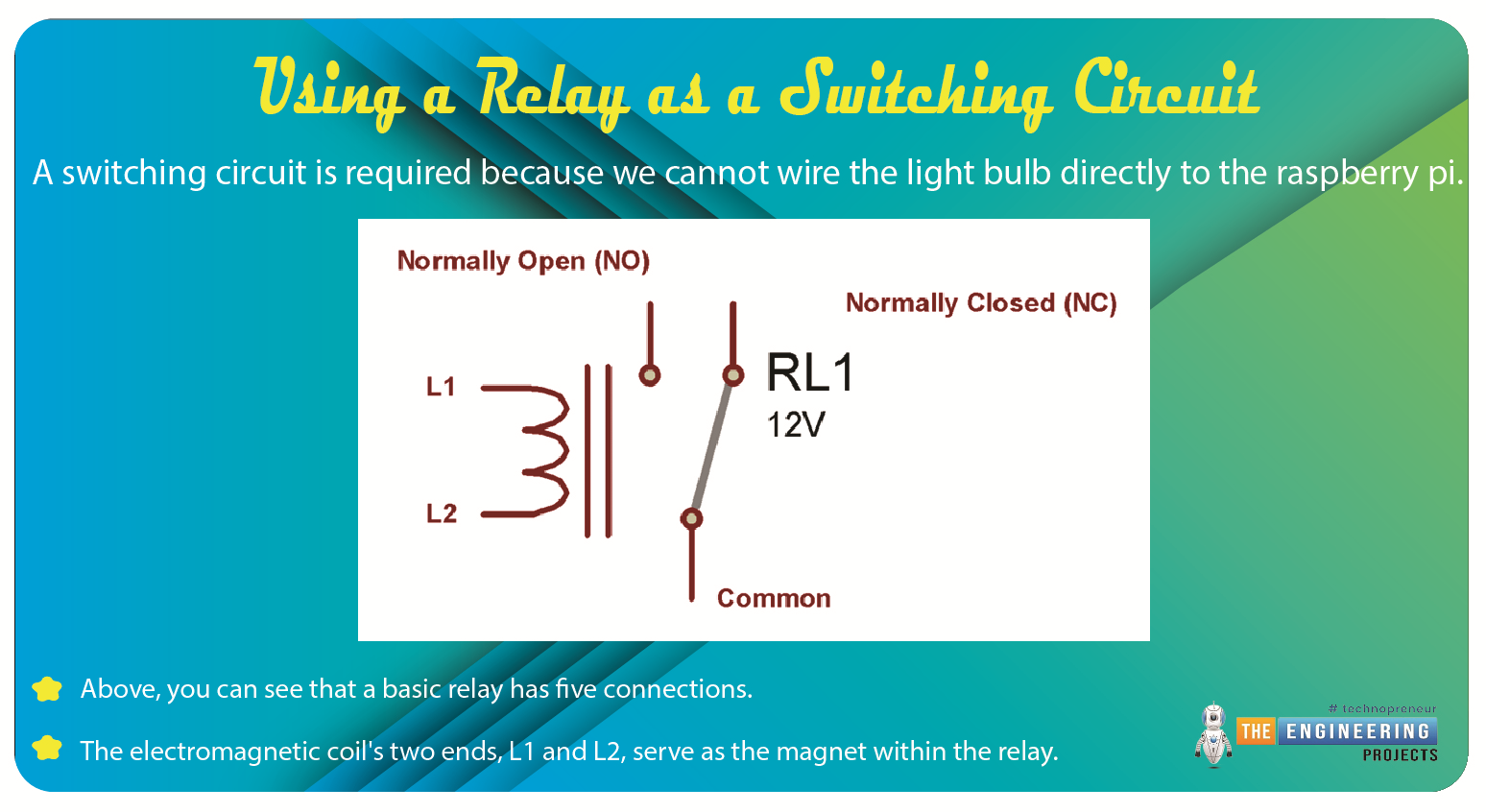
Above, you can see that a basic relay has five connections. The electromagnetic coil's two ends, L1 and L2, serve as the magnet within the relay. Directly connecting the L1 Or L2 to a DC power supply is possible. The coil becomes an electromagnet when it is supplied with an electric current. Unlike the usually closed (NC) and ordinarily open (NO) terminals, the Common terminal can be moved.
Working of Relays
The NC terminal serves as the home of the common terminal, which is held in place using sprint tension. This is the relay's initial setting. In a standard setup, the NC and COM terminals of a relay are linked when the device is positioned on a flat surface. The coil becomes magnetized whenever a voltage is placed between coil terminals L1 and L2. The spring tension is opposed by the magnetic force that pulls the common terminal off of NC and onto NO. As long as the relay is live, there will be continuity between NO and COM. Magnetization ceases when the coil voltage is removed, and the common terminal reverts to the NC Terminal, as depicted below.
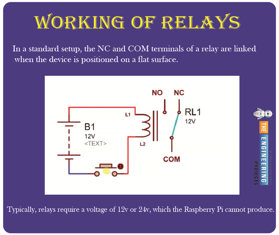
To conclude, we can switch any AC device on and off with a relay if we know how to do so effectively. However, the issue of activating the relay itself remains to be seen. Typically, relays require a voltage of 12v or 24v, which the Raspberry Pi cannot produce. A microprocessor cannot supply the 30-50mA current required for relays that operate on +5v coil voltage. Consequently, a relay switching circuit is required rather than a direct connection to the raspberry pi.
An explanation of relay control
By adjusting the voltage at the GPIO pins, you may toggle the state of any relay module, whether it's attached directly to the ports or via a relay HAT. Using Python in conjunction with the GPIO library is the simplest solution.
After establishing a connection to the desired GPIO pin, changing its state is as simple as issuing a single command in Python. Pins 26, 20, and 21 on the GPIO header are used for the Waveshare HAT relays. For this reason, for instance, the first relay's power supply can be switched after a delay of just one second.
Sample code
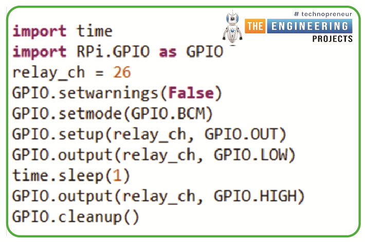
import time
import RPi.GPIO as GPIO
relay_ch = 26
GPIO.setwarnings(False)
GPIO.setmode(GPIO.BCM)
GPIO.setup(relay_ch, GPIO.OUT)
GPIO.output(relay_ch, GPIO.LOW)
time.sleep(1)
GPIO.output(relay_ch, GPIO.HIGH)
GPIO.cleanup()
Using a signal from a microcontroller like a Raspberry Pi, we can switch a DC load with a transistorized switching circuit. Just below, you'll find a quick breakdown of how transistors function.
Here is the complete circuit for using a transistor to switch a relay using a Raspberry Pi.
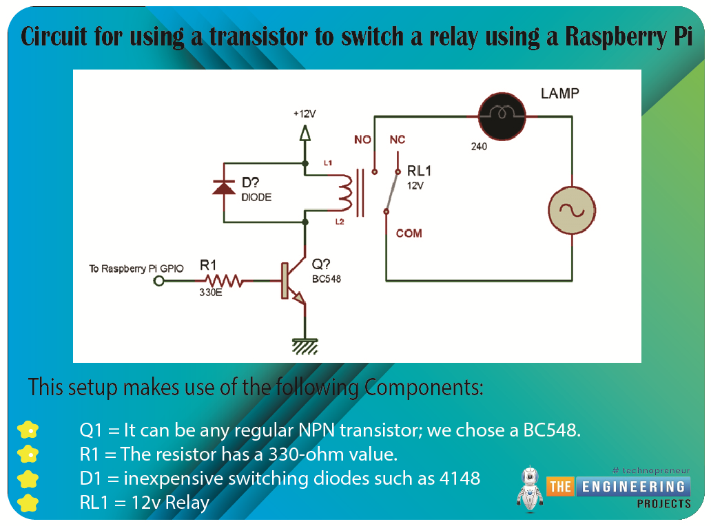
As demonstrated in the diagram above, the transistor controls the switching of the relay coil, while the relay terminals control the AC load. Any AC load can be connected to a Raspberry Pi using the circuit above and turned on or off remotely.
This setup makes use of the following Components:
Q1 = It can be any regular NPN transistor; we chose a BC548.
R1 = The resistor has a 330-ohm value.
D1 = inexpensive switching diodes such as 4148
RL1 = 12v Relay
Diode D1 is a protection device that allows the relay to be easily turned off, as shown in the diagram.
The transistor base resistor will receive the signal from the raspberry pi pin. Here's a program that will turn on a relay when the output is set to HIGH and turn it off when the output is set to LOW.
Sample code
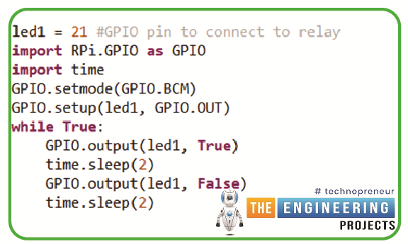
led1 = 21 #GPIO pin to connect to relay
import RPi.GPIO as GPIO
import time
GPIO.setmode(GPIO.BCM)
GPIO.setup(led1, GPIO.OUT)
while True:
GPIO.output(led1, True)
time.sleep(2)
GPIO.output(led1, False)
time.sleep(2)
The function of transistors in a relay module.
A transistor can open and close an electronic gate millions of times per second, allowing electrical signals to pass through and out. As long as electricity flows, the circuit is active; otherwise, it is cut off. Modern telecommunications systems are built on complicated switching circuits that rely on transistors. Circuits can also flip at extremely fast rates, with some offering switching speeds of over 100 billion on/off cycles per second or hundreds of gigahertz.
A logic gate, constructed from several transistors, compares input currents and generates a unique result. Logic gates allow computers to use Boolean algebra to make straightforward decisions. Modern computers and software applications are built on these methods.
Four-channel relay module
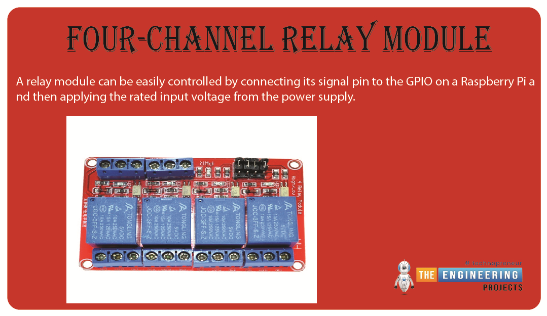
A relay module can be easily controlled by connecting its signal pin to the GPIO on a Raspberry Pi and then applying the rated input voltage from the power supply. The necessary transistors and switching circuitry are already on this board. All you have to do to use such a relay module is connect the GND of the power source that powers the relay module (5v/12v/24v) to the GND of the raspberry pi.
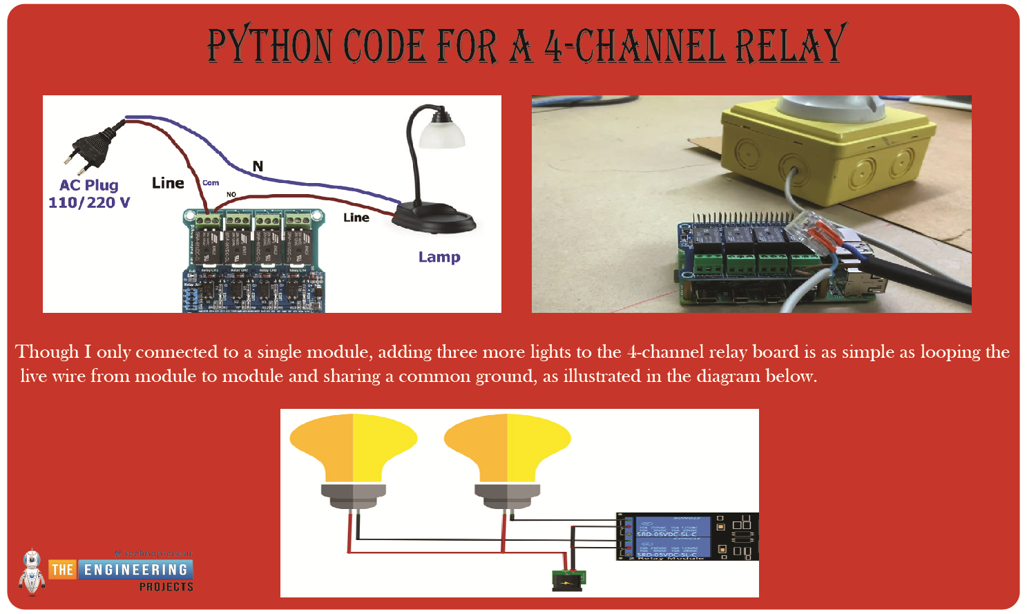
Python code for a 4-channel relay
import RPi.GPIO as GPIO
import time
Relay_Ch1 = 26
Relay_Ch2 = 20
Relay_Ch3 = 21
GPIO.setwarnings(False)
GPIO.setmode(GPIO.BCM)
GPIO.setup(Relay_Ch1,GPIO.OUT)
GPIO.setup(Relay_Ch2,GPIO.OUT)
GPIO.setup(Relay_Ch3,GPIO.OUT)
print("Setup The Relay Module is [success]")
try:
while True:
#Control the Channel 1
GPIO.output(Relay_Ch1,GPIO.LOW)
print("Channel 1:The Common Contact is access to the Normal Open Contact!")
time.sleep(0.5)
GPIO.output(Relay_Ch1,GPIO.HIGH)
print("Channel 1:The Common Contact is access to the Normal Closed Contact!\n")
time.sleep(0.5)
#Control the Channel 2
GPIO.output(Relay_Ch2,GPIO.LOW)
print("Channel 2:The Common Contact is access to the Normal Open Contact!")
time.sleep(0.5)
GPIO.output(Relay_Ch2,GPIO.HIGH)
print("Channel 2:The Common Contact is access to the Normal Closed Contact!\n")
time.sleep(0.5)
#Control the Channel 3
GPIO.output(Relay_Ch3,GPIO.LOW)
print("Channel 3:The Common Contact is access to the Normal Open Contact!")
time.sleep(0.5)
GPIO.output(Relay_Ch3,GPIO.HIGH)
print("Channel 3:The Common Contact is access to the Normal Closed Contact!\n")
time.sleep(0.5)
except:
print("except")
GPIO.cleanup()
Though I only connected to a single module, adding three more lights to the 4-channel relay board is as simple as looping the live wire from module to module and sharing a common ground, as illustrated in the diagram below.
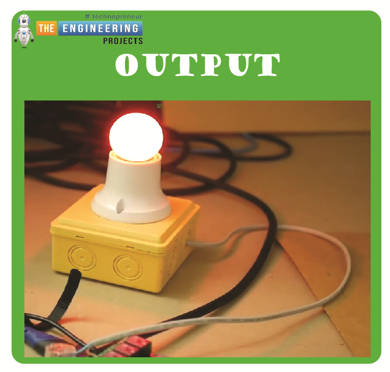
At this point, the raspberry pi 4 controls the 4-channel relay module. Closed-loop control for high-powered equipment is made possible by incorporating such code in considerably more complex scripts that consider human input or sensor readings.
Output
Conclusion
Due to human fallibility, it is necessary to install home automation systems to ensure electricity is used efficiently and safely wherever possible. As an intelligent platform, Raspberry Pi enables the interconnection and remote control of many home appliances over a single network infrastructure—specifically, the internet. Because of the convenience provided by these appliances.
Home automation systems are a promising new trend in appliance manufacturing to reduce energy use and human error. Raspberry pi-based automation is cutting-edge and innovative. Automating tasks is easier with a Raspberry Pi.
Tell me if you had trouble understanding it or connecting your relay module to your Raspberry Pi 4 in the comments. The next tutorial will teach you how to connect a GPS module to a Raspberry Pi 4.