


Interface Remote Control RF Module (433mhz) with Pi 4


Welcome to the next tutorial of our raspberry pi 4 programming course. The last guide covered connecting a Sharp infrared distance measurement sensor to a Raspberry Pi 4. Infrared (IR) sensors were demonstrated to be widely used for nearby object recognition and motion tracking. But in this session, we'll utilize Raspberry Pi 4 to create a radio-frequency (RF) remote control that can be used to operate the gadgets wirelessly. With the help of this RF remote control, we can Power On/Off the devices.
Components
Transmitter Side
RF Transmitter
HT12E IC
4 Push Buttons
750k resistor
9 Volt battery
Receiver Side
Raspberry Pi
16x2 LCD
10K POT
Breadboard
1K Resistor (Five)
33K resistor
HT12D IC
RF Receiver
LEDs (Five)
4 10K resistor
Jumper wires
RF Module
This ASK Hybrid Transmitter/Receiver module communicates at 433Mhz. For optimal range and frequency stability, this module utilizes a crystal-stabilized oscillator. The module requires only a single external antenna.

This module is for you if you need RF communication over a great distance at a low cost. The high levels of background noise at this frequency and in its Analog technology mean that this module cannot directly transmit data via the UART communication of a PC or microcontroller. Using encoder and decoder ICs, we may utilize this module to retrieve information from background static.
At full Power, a transmitter's range is over 100 meters; at 5 volts, it's around 50-60 meters when employing a single-code wire antenna measuring just 17 centimetres.
There are two primary limitations placed on the wireless system designer: the system must function within a particular range and send a certain quantity of data within a given data rate. The RF module is incredibly compact and can run on a broad voltage spectrum (from 3V to 12V).
Transmitter and receiver RF modules operating at 433 MHz constitute the bulk of the RF modules. Because the carrier frequency is completely suppressed during transmission of logic zero, the transmitter's power consumption is significantly reduced during battery operation. A logic one signal turns the carrier on to around 4.5mA at 3 volts when it is off at 0 volts. The data is transmitted serially from the transmitter to the tuned receiver. Two microcontrollers are suitably interfaced with the transmitter and receiver for communication.

RF Transmitter Features
Range of Operation: 433 MHz
Power at the Output: 4-16 dBm
Power supply input: 3 to 12-volt dc
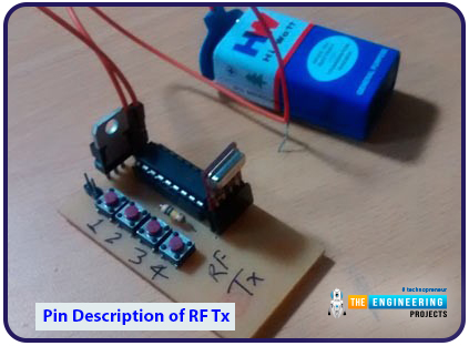
Pin Description of RF Tx
GND stands for "ground," which indicates a supply connection to the earth.
Data in - When serial data is received from an encoder, it is input via this pin.
VCC - This jack must be wired to Vcc - +5 Volt.
Antenna - The data transmission antenna wraps around this pin.
RF Receiver Features
The sensitivity is -105 dBm.
IF Rate of 1 megahertz.
Less need for a power supply.
The current is 3.5 mA.
Five-volt power source.
Pin Description of RF Rx
GND - Ground
Data In - This pin give
s output serial data to Decoder
Vcc - +5 Volt should be connected to this pin
Vcc - +5 Volt should be connected to this pin
GND - Ground
GND - Ground
Antenna - A wrapped connection to this pin for proper Reception of data
Encoder IC usage
The output pin on an HT12E is used for its principal purpose, which is to transmit a 12-bit encoded signal. The IC's built-in Oscillator makes it simple to put it to use. The IC may operate from 2.4V – 12V, although in most cases, +5V is supplied to the Vcc (pin 18), while pin 9 is left unconnected. Connect pin 14 (Transmission Enable) to the ground terminal to start the transmission process. This IC has an integrated oscillator, which is necessary for data decoding. To activate it, we need only connect pins 15 and 16 (OSC1 and OSC2) with a 1M resistor. The address, which is 8 bits long, must be established using pins A0–A7, and the data to be transmitted, which is 4 bits long, must be given to pins AD0–AD1. Your Decoder must have the same address for the two devices to communicate. Below is a simple HT12E IC wiring diagram.

Through the use of a series of ground connections on the address pins, I have programmed the eight-bit address data in the circuit above to read 0b00000000. Any eight pins can be made high by connecting it to 5V to improve security. A +5V supply, such as that provided by a voltage regulator such as 7805, is used to power the entire IC. Any Digital IC capable of supplying the required 4-bit data will do, and its pins AD3, AD2, AD1, and AD0 will be linked to those. They can be connected to switches for manual data transmission and Reception. In this example, I have set all four data bits to be zero (low), and the HT12D decoder IC's output will be the same type of bits. Similarly, if we modify these four bits, the HT12D's output will change accordingly.
The Dout pin is where you'll find the encoded 12-bit value (pin 17). The HT12D has to receive this information to decode it, and it can do so via wire or a wireless channel (such as RF or IR). Following this, you will know the necessary to configure the HT12D.
HT12D RF decoder usage.
HT12D's main job is to interpret the 12-bit signal through the input pin. The IC's built-in Oscillator makes it simple to put it to use. The IC's ground (pin 9) and power (pin 18) terminals should be connected to 5V. This IC has an integrated oscillator, which is necessary for data decoding. It's activated by connecting pins 15 and 16 (OSC1 and OSC2) using a 470K resistor. Received data in increments of 4 bits are available on pins AD0 and AD1, and an address in increments of 8 bits must be programmed using pins A0 through A7. The Decoder's address must match the encoder's if you want to use it successfully. See below for a simplified circuit depiction of the HT12D IC.

Through the use of a series of ground connections on the address pins, I have programmed the eight-bit address data in the circuit above to read 0b00000000. Any eight pins can be made high by connecting it to 5V to improve security. A +5V supply, such as that provided by a voltage regulator such as 7805, is used to power the entire IC. Any Digital IC capable of reading 4-bit data will work with the AD3, AD2, AD1, and AD0 pins. As a bonus, they can be hooked up to an LED so you can see the data being transmitted in real-time. Due to the uncertainty of the Encoder IC's Input signal, the four-bit output data is represented as a question mark. If there is any good information received, it can be read off of these four pins.
The HT12E Encoder IC's description is provided to help you learn how to encode a 4-bit data stream for transmission to the IC's input pin.
Working Explanation
In this setup, four buttons on the transmitter side (the remote) activate corresponding LEDs on the receiver side. Whenever one of the four buttons is pressed, a signal is sent to an encoder IC, which then passes it on to a radio frequency (RF) transmitter, which broadcasts it into the surrounding environment. The RF receiver picks up the signal, which then transmits the 4-bit decoded signal to the Raspberry Pi through the Decoder IC HT12D. The Raspberry Pi will then interpret these data snippets, perform the appropriate action, and activate the corresponding LED. Once a key is pressed, a buzzer will sound for one second. In addition, a 16x2 LCD shows whether the LEDs are on or off.

For the demonstration, this project only uses four LEDs; to initiate any action, press the appropriate button on the "RF Remote." The LEDs may be swapped out for AC home appliances via the relay, and the same "RF Remote" can be used to operate both sets of lights wirelessly. Consequently, you may use the same circuit for your RF-based Raspberry Pi-based home automation project. You can see all of the Home Automation Projects we've produced in the past, including Bluetooth, DTMF, GSM control, and more, right here: Home Automation Projects.
Circuit Explanation
This RF remote control for the Raspberry Pi features an easy-to-assemble circuit consisting of just the Pi board, a few buttons, an LCD, an RF pair, and an encoder/decoder IC. Raspberry Pi manages the LCD, processes input, and communicates results. However, any Raspberry Pi model should do in this case; Raspberry Pi 3 was utilized. The circuit consists of an RF receiver section and an RF transmitter section. The below figure depicts both circuits.

LCD pins rs, en, d4, d5, d6, and d7 from the receiver are wired to GPIO pins 11, 10, 6, 5, 4, 1, and 4 in 4-bit Mode. The RF receiver picks up the signal and decodes it by the HT12D IC once it has been sent from the RF transmitter. Decoder IC pins D8, D9, D10, and D11 of the HT12D are linked straight to wiringPI GPIO pins 25, 24, 23, and 22. LEDs are wired to wiringPi GPIO pins 26, 27, 28, and 29 for output. When a key is pressed, the buzzer connected to wiringPi GPIO 0 sounds an alarm.
The HT12E Encoder IC is part of the RF transmitter circuit, with four buttons used to toggle the LEDs on and off. Every address line in an encoder/decoder IC is grounded.
Installation of wiringPi Library in pi 4
To access the Raspberry Pi's GPIO pins in C, we must use the wiringPi Library, much like how Python programmers include the import RPi.GPIO as an IO header file. You can use Terminal or an SSH client like Putty to execute the commands below one by one to complete the installation. If you want more information on how to work with and set up the Raspberry Pi, read our introduction to Raspberry Pi tutorial.

sudo apt-get install git-core
sudo apt-get update
sudo apt-get upgrade
git clone git://git.drogon.net/wiringPi
cd wiringPi
git pull origin
cd wiringPi
./build
Test the installation of wiringPi Library by using the below commands:

gpio -v
gpio readall
Programming Explanation
We start by including the necessary header files and defining the LCD's pins, and then we initialize certain variables and connection pins for receiving input and displaying LED indications.

#include "wiringpi.h"
#include "wiringserial.h"
#include "stdio.h"
#include "string.h"
#define RS 11
#define EN 10
#define D4 6
#define D5 5
#define D6 4
#define D7 1
#define led1 26
#define led2 27
#define led3 28
#define led4 29
#define buzz 0
#define d1 25
#define d2 24
#define d3 23
#define d4 22
int am = 0;
int flag1=am ,flag2=am ,flag3=am ,flag4=am;
Then, in the void setup() procedures, we tell all the GPIO Pins what to do.

void setup()
{
if (wiringPiSetup () == -1)
{
clear();
print("Unable to start");
setCursor(0,1);
print("wiringPi");
}
pinMode(led1, OUTPUT);
pinMode(led2, OUTPUT);
pinMode(led3, OUTPUT);
pinMode(led4, OUTPUT);
We have used the digitalRead and digitalWrite functions in the code to receive and send the Decoder's output to an LED and a device, respectively.

while(1)
{
setCursor(0,0);
print("D1 D2 D3 D4");
if(digitalRead(d1)==0)
{
flag1++;
setCursor(0,1);
if(flag1%2==1)
{
print("ON ");
digitalWrite(led1,HIGH);
}
Additional functions utilized in this project are listed below. To send a command to the LCD, use the void lcdcmd method, and to provide data to the LCD, use the void write function. You can call the void clear() function to reset the LCD. The cursor is used to deliver a string to the LCD instead of printing it. To start the LCD up in 4-bit Mode, call the void to begin, and use the void buzzer() function to make the buzzer sound. Find the complete code for this RF remote control using a Raspberry Pi below.
Full code
#include "wiringpi.h"
#include "wiringserial.h"
#include "stdio.h"
#include "string.h"
#define RS 11
#define EN 10
#define D4 6
#define D5 5
#define D6 4
#define D7 1
#define led1 26
#define led2 27
#define led3 28
#define led4 29
#define buzz 0
#define d1 25
#define d2 24
#define d3 23
#define d4 22
int am = 0;
int flag1=am ,flag2=am ,flag3=am ,flag4=am;
void lcdcmd(unsigned int ch)
{
int temp=0x80;
digitalWrite(D4, temp & ch<<3);
digitalWrite(D5, temp & ch<<2);
digitalWrite(D6, temp & ch<<1);
digitalWrite(D7, temp & ch);
digitalWrite(RS, LOW);
digitalWrite(EN, HIGH);
delay(10);
digitalWrite(EN, LOW);
digitalWrite(D4, temp & ch<<7);
digitalWrite(D5, temp & ch<<6);
digitalWrite(D6, temp & ch<<5);
digitalWrite(D7, temp & ch<<4);
digitalWrite(RS, LOW);
digitalWrite(EN, HIGH);
delay(10);
digitalWrite(EN, LOW);
}
void write(unsigned int ch)
{
int temp=0x80;
digitalWrite(D4, temp & ch<<3);
digitalWrite(D5, temp & ch<<2);
digitalWrite(D6, temp & ch<<1);
digitalWrite(D7, temp & ch);
digitalWrite(RS, HIGH);
digitalWrite(EN, HIGH);
delay(10);
digitalWrite(EN, LOW);
digitalWrite(D4, temp & ch<<7);
digitalWrite(D5, temp & ch<<6);
digitalWrite(D6, temp & ch<<5);
digitalWrite(D7, temp & ch<<4);
digitalWrite(RS, HIGH);
digitalWrite(EN, HIGH);
delay(10);
digitalWrite(EN, LOW);
}
void clear()
{
lcdcmd(0x01);
}
void setCursor(int x, int y)
{
int set=0;
if(y==0)
set=128+x;
if(y==1)
set=192+x;
lcdcmd(set);
}
void print(char *str)
{
while(*str)
{
write(*str);
str++;
}
}
void begin(int x, int y)
{
lcdcmd(0x02);
lcdcmd(0x28);
lcdcmd(0x06);
lcdcmd(0x0e);
lcdcmd(0x01);
}
void buzzer()
{
digitalWrite(buzz, HIGH);
delay(1000);
digitalWrite(buzz, LOW);
}
void setup()
{
if (wiringPiSetup () == -1)
{
clear();
print("Unable to start");
setCursor(0,1);
print("wiringPi");
}
pinMode(led1, OUTPUT);
pinMode(led2, OUTPUT);
pinMode(led3, OUTPUT);
pinMode(led4, OUTPUT);
pinMode(buzz, OUTPUT);
pinMode(RS, OUTPUT);
pinMode(EN, OUTPUT);
pinMode(D4, OUTPUT);
pinMode(D5, OUTPUT);
pinMode(D6, OUTPUT);
pinMode(D7, OUTPUT);
pinMode(d1, INPUT);
pinMode(d2, INPUT);
pinMode(d3, INPUT);
pinMode(d4, INPUT);
digitalWrite(led1, LOW);
digitalWrite(led2, LOW);
digitalWrite(led3, LOW);
digitalWrite(led4, LOW);
digitalWrite(buzz, LOW);
begin(16,2);
}
//void loop()
void main()
{
setup();
clear();
print(" RF Module ");
setCursor(0,1);
print(" Interfacing ");
delay(2000);
clear();
print("Raspberry Pi");
setCursor(0,1);
print("Circuit Digest");
delay(2000);
clear();
print("System Ready");
delay(1000);
clear();
setCursor(0,1);
print("OFF OFF OFF OFF");
while(1)
{
setCursor(0,0);
print("D1 D2 D3 D4");
if(digitalRead(d1)==0)
{
flag1++;
setCursor(0,1);
if(flag1%2==1)
{
print("ON ");
digitalWrite(led1,HIGH);
}
else
{
print("OFF");
digitalWrite(led1,LOW);
}
buzzer();
while(digitalRead(d1)==0);
}
else if(digitalRead(d2)==0)
{
flag2++;
setCursor(4,1);
if(flag2%2==1)
{
print("ON ");
digitalWrite(led2,HIGH);
}
else
{
print("OFF");
digitalWrite(led2,LOW);
}
buzzer();
while(digitalRead(d2)==0);
}
else if(digitalRead(d3)==0)
{
flag3++;
setCursor(8,1);
if(flag3%2==1)
{
print("ON ");
digitalWrite(led3,HIGH);
}
else
{
print("OFF");
digitalWrite(led3,LOW);
}
buzzer();
while(digitalRead(d3)==0);
}
else if(digitalRead(d4)==0)
{
flag4++;
setCursor(12,1);
if(flag4%2==1)
{
print("ON ");
digitalWrite(led4,HIGH);
}
else
{
print("OFF");
digitalWrite(led4,LOW);
}
buzzer();
while(digitalRead(d4)==0);
}
}
}
Conclusion
Transmitted modules, which plug into the Raspberry Pi, allow for the transmission of radio frequency signals at a range of 433 MHz to remote receivers. Devices like remote controllers, headphones, baby phones, and additional Raspberry Pis can pick up these signals. An RF module's performance will vary from that of other radio-frequency devices depending on several parameters, such as the strength of the transmitter, which directly affects the range of the signal it can collect. The downside is that this will significantly reduce the battery life of the transmitter device. Using this device with a higher transmission power will also cause interference with nearby RF appliances. The subsequent tutorial will cover the Bluetooth connection between a Raspberry Pi 4 and an ESP32.


