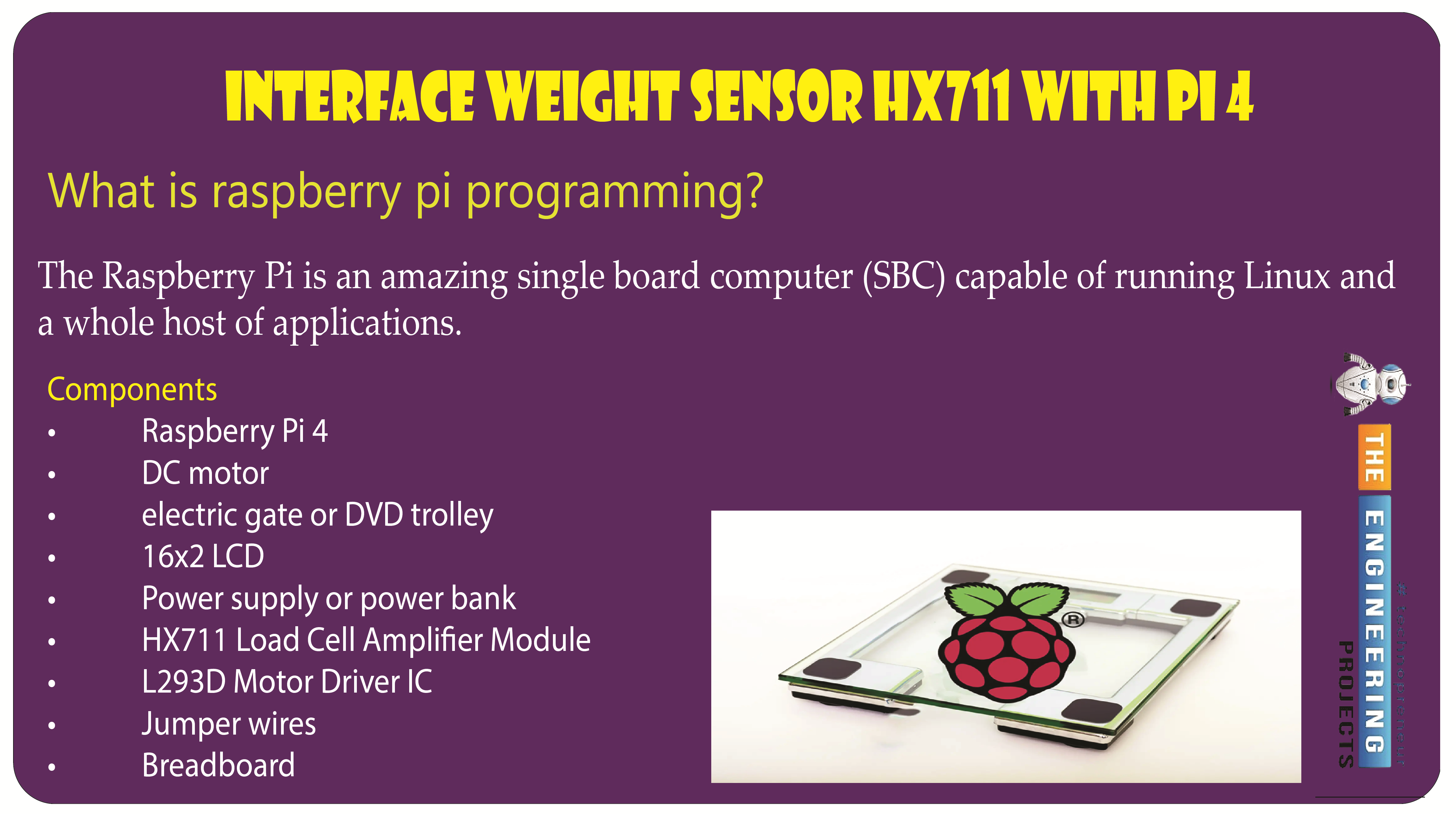
Interface Weight Sensor HX711 with Raspberry Pi 4


Welcome to the next tutorial of our raspberry pi programming tutorial. The previous tutorial showed us how to set up a weather station using the Internet of Things (IoT) on a Raspberry Pi 4. First, we studied how a weather station works on a fundamental level. Then we developed a Python script to collect data from the station. In contrast, we'll construct an automatic gate using a Raspberry Pi, a load cell, and an HX711 weight sensor.
These pressure-sensitive gates are common in shopping centers and showrooms; they open when someone is in the immediate vicinity and close again when the person is out of sight. Like the Automatic Gate, we just made, this one will open in response to weight or pressure and stay that way until the force is removed. If you remove the load from this gate, it will close independently.
In this example, a DC motor is the gate, and a piece of rigid cardboard is the load-bearing surface.
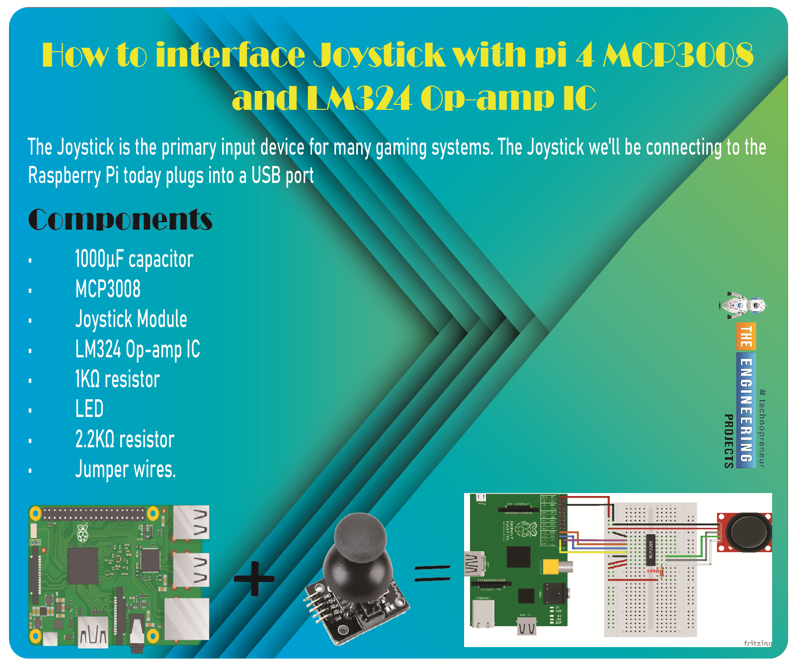
Components
Raspberry Pi 4
DC motor
electric gate or DVD trolley
16x2 LCD
Power supply or power bank
HX711 Load Cell Amplifier Module
L293D Motor Driver IC
Jumper wires
Breadboard
Load cell, HX711 Weight Sensor Module, and Nut Bolts
A load cell transducer converts mechanical input (force or pressure) into an electric signal. For example, many strain gauges are fastened to an elastic element (with a highly repeatable deflection waveform) to create a load cell.
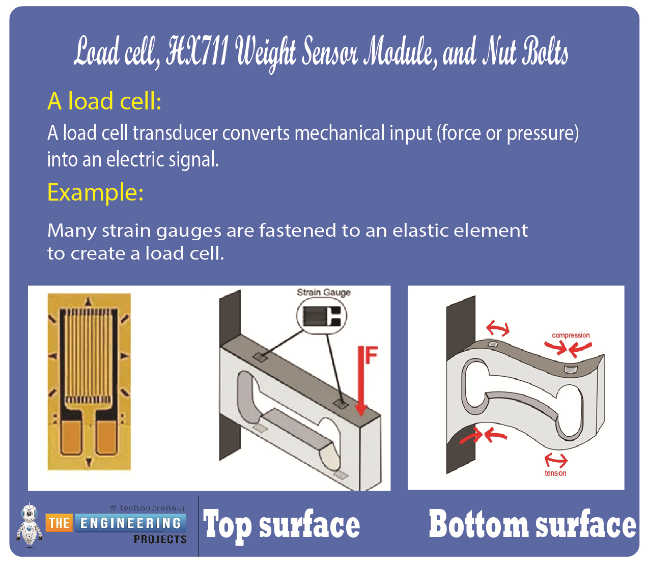
The load cell depicted in the figure above features four strain gauges, two on each top and bottom surface.
The elastic element of the resistive load cell illustrated above deflects under the applied force, causing a strain at the stress points. For example, see how the animation below depicts how two strain gauges are under tension while the other two are under compression.
The load cell's metal spring element undergoes elastic deformation due to the weight being measured. Its electrical output scales linearly with the applied force. Load cells contain a strain gauge that bends under stress. Strain gauges produce an electrical signal upon deformation due to a change in their effective resistance. Four strain gauges configured as a Wheatstone bridge make up a typical load cell. While load cells can measure loads as small as 5 kilograms or as much as 100 kilograms, we utilized one that measured up to 40 kilograms.
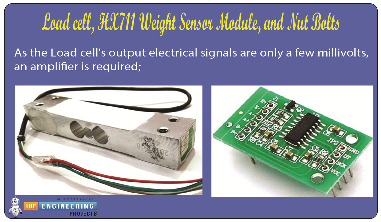
As the Load cell's output electrical signals are only a few millivolts, an amplifier is required; enter the HX711 Weighing Sensor. The HX711 chip inside the HX711 Weight Sensor Module is a 24 high-precision A/D converter. The HX711 features two channels for analog input, and their gain can be programmed up to 128. The HX711 Module boosts the Load cells' light electrical output. The Arduino uses that amplified, digitally transformed signal to calculate the weight.
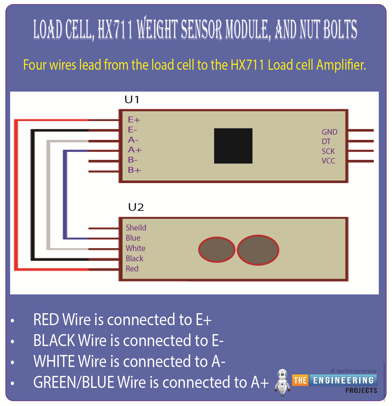
Four wires lead from the load cell to the HX711 Load cell Amplifier. Red, black, white, and green/blue are the colors of these four wires. Certain modules may have different wire colors than others. Please find the diagram and connecting information below:
RED Wire is connected to E+
BLACK Wire is connected to E-
WHITE Wire is connected to A-
GREEN/BLUE Wire is connected to A+
Channel A or Channel B differential input is chosen by the input multiplexer and fed into the low-noise programmable gain amplifier (PGA). When a 5V supply is connected to the AVDD analog power supply pin, the gain of Channel A can be set to 128 or 64, yielding a full-scale differential input voltage of 20mV or 40mV, respectively. A constant gain of 32 is applied to Channel B. Since the regulator for the analog power used by the Analog-digital converter and the sensor is integrated into the chip, there is no longer any need for a separate supply regulator. The clock input can be set manually. It can come from a crystal or on-chip oscillator that doesn't need anything extra to function. The initialization of digital interfaces is made more accessible by on-chip power-on reset circuitry. The internal registers can be used immediately without any programming. The HX711's pins are used for all of its controls.
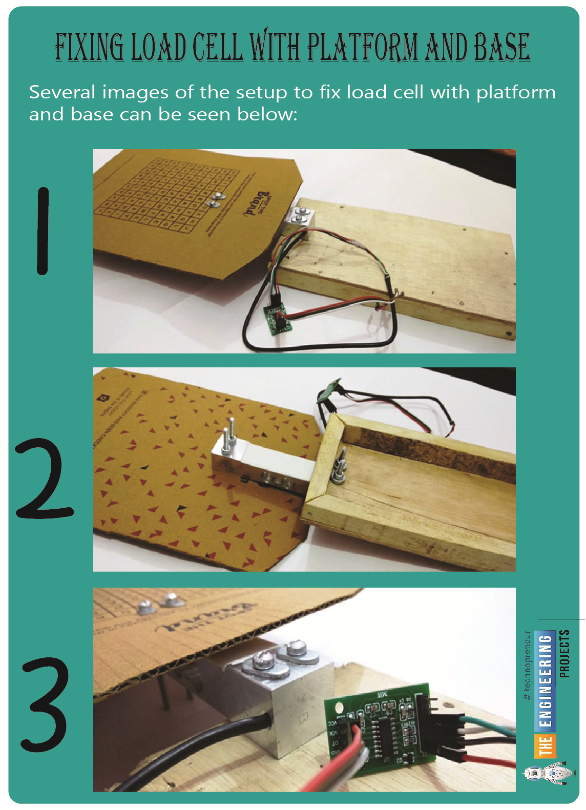
Fixing Load Cell with Platform and Base
To make this system function, a Load Cell must be buried beneath the door's threshold to detect the weight of someone standing nearby. But, for the sake of demonstration, we have secured the load cell beneath a sturdy piece of cardboard. This will allow us to test the gate by placing a weight on the cell. The load cell has been securely fastened to the wooden base with nuts and bolts. Several images of the setup can be seen below:
The resistive load cell is based on the piezo-resistive concept. The sensor's resistance changes as a function of the applied force or stress. When an external voltage is introduced, the output voltage will fluctuate due to the change in resistance.
A capacitive load cell measures the load by measuring the voltage required to cause a change in the capacitance of a system. The capacitance of a standard parallel plate capacitor scales inversely with the distance between both the plates and proportionally with the area of overlap between the plates relative to the dielectric between them.
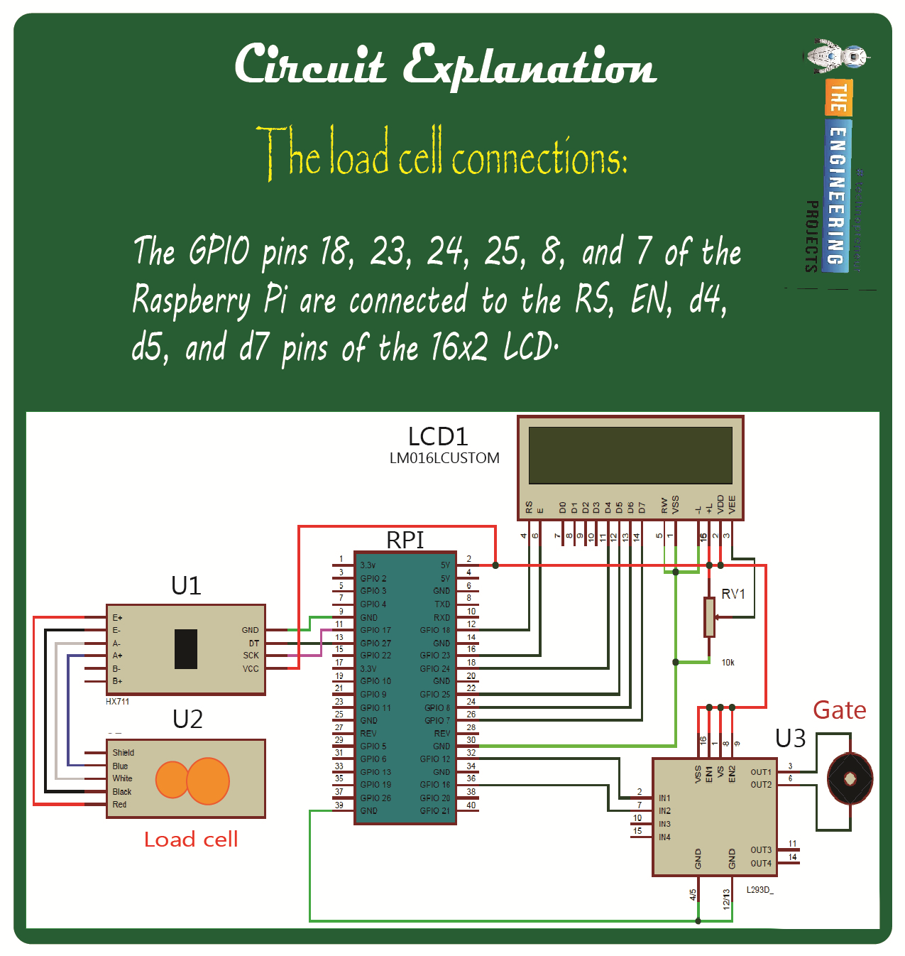
Circuit Explanation
The wiring is simple for this automatic gate, and a diagram is included for reference. The GPIO pins 18, 23, 24, 25, 8, and 7 of the Raspberry Pi are connected to the RS, EN, d4, d5, and d7 pins of the 16x2 LCD. The DT and SCK pins of the HX711 Module are wired to GPIO pins 27 and 17, respectively, on the Raspberry Pi. In contrast, the DATA and SCK pins of the Motor Driver L293D are wired to GPIO pins 12 and 16, respectively. Already stated and depicted in the circuit diagram below are the load cell connections necessary to use the HX711 Module.
Analog Inputs
A differential input channel connects straight to the differential signal sent by a bridge sensor. Gain settings of 128 or 64 are selectable via programming. Since the sensor output signal is typically somewhat weak, high gains are required. These improvements translate to an input differential voltage of 20mV or 40mV at full scale when a 5V supply is connected to the AVDD port. The gain of the differential input on channel B is always 32. With a 5V supply at the AVDD pin, an input voltage of 80mV is possible.
Working Explanation
Raspberry Pi 4 was used as the central processing unit for this project. First, the pressure near the gate is measured by a load cell, which then sends an analog voltage signal to the HX711 Load sensor Module. Next, the output from the Load cell is amplified and converted to digital form by the HX711, a 24-bit analog-to-digital converter. After that, the Raspberry Pi receives the magnified value. The HX711 output is now converted to a weight value by Raspberry Pi. The motor driver IC L293D is then used by the Raspberry Pi to control the gate based on a comparison with the reference weight. In this case, we're using a DC motor as the gate.
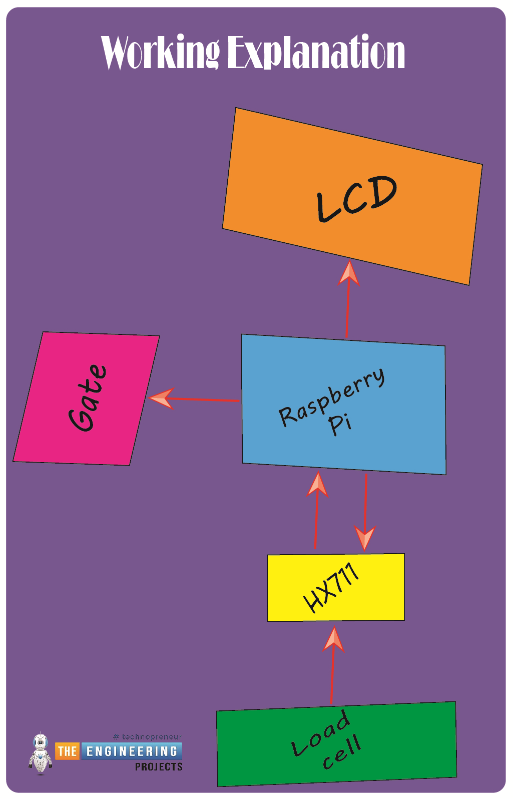
We've set the threshold at 100 grams to ensure that only people weighing more than that are allowed through the gate. Once we've removed the 100 grams or the individual is no longer present, the gate will lock. The standard weighting can be adjusted to fit your needs. The state of the gate can be shown on a 16x2 LCD screen (optional). We have created Python software to automate the entire procedure; the program's source code is available for download, along with a video demonstration.
Programming Explanation
In this case, Python will be used for the coding. We did not use a library to connect the HX711 load sensor to the Raspberry Pi in this project. Our only guide was the HX711 datasheet and the accompanying application notes. Nonetheless, libraries are available for this purpose; by including the library, you can obtain the weight with minimal effort.
Then, the GPIO Library was implemented, with pins for the LCD, HX711, and DC motor defined and various calculation variables being declared.
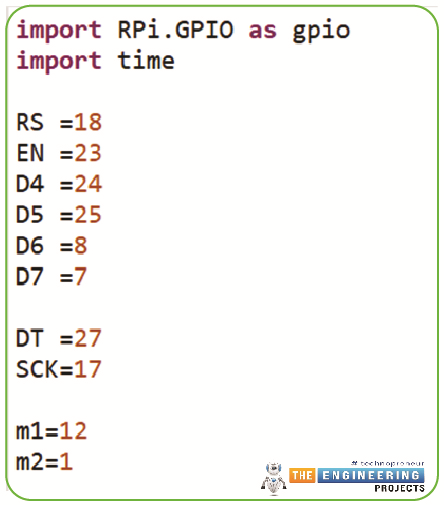
import RPi.GPIO as gpio
import time
RS =18
EN =23
D4 =24
D5 =25
D6 =8
D7 =7
DT =27
SCK=17
m1=12
m2=1
Following that, the below code will retrieve information from the HX711 Module.
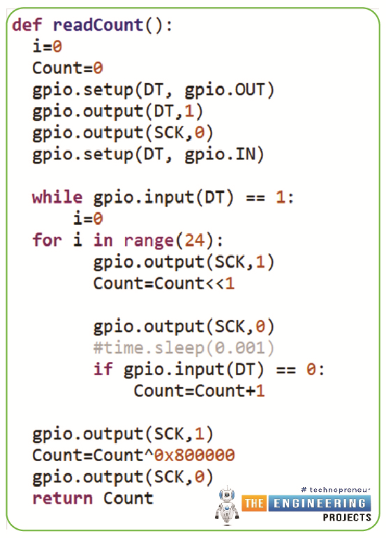
def readCount():
i=0
Count=0
gpio.setup(DT, gpio.OUT)
gpio.output(DT,1)
gpio.output(SCK,0)
gpio.setup(DT, gpio.IN)
while gpio.input(DT) == 1:
i=0
for i in range(24):
gpio.output(SCK,1)
Count=Count<<1
gpio.output(SCK,0)
#time.sleep(0.001)
if gpio.input(DT) == 0:
Count=Count+1
gpio.output(SCK,1)
Count=Count^0x800000
gpio.output(SCK,0)
return Count
To open or shut the gate, we now compare the HX711 Module's data with a reference weight in the main function.
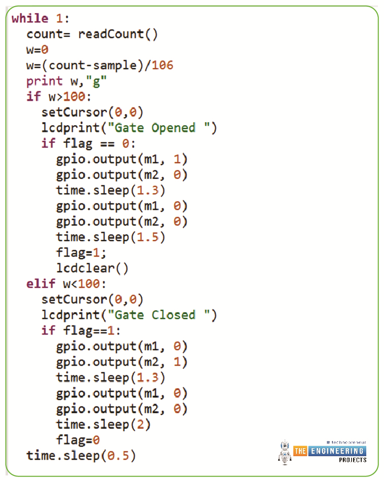
while 1:
count= readCount()
w=0
w=(count-sample)/106
print w,"g"
if w>100:
setCursor(0,0)
lcdprint("Gate Opened ")
if flag == 0:
gpio.output(m1, 1)
gpio.output(m2, 0)
time.sleep(1.3)
gpio.output(m1, 0)
gpio.output(m2, 0)
time.sleep(1.5)
flag=1;
lcdclear()
elif w<100:
setCursor(0,0)
lcdprint("Gate Closed ")
if flag==1:
gpio.output(m1, 0)
gpio.output(m2, 1)
time.sleep(1.3)
gpio.output(m1, 0)
gpio.output(m2, 0)
time.sleep(2)
flag=0
time.sleep(0.5)
In addition, we define several LCD-specific methods, such as begin(), which initializes the display, lcdcmd(ch), which sends commands to the display, lcdwrite(ch), which prints a single character on the display, lcdclear(), which clears the display, and lcdprint(Str), which prints a string. The complete code is included below for your perusal.
As we have shown, an Automated Gate that detects weight using a Raspberry Pi and a load cell is relatively easy to make.
Complete Code
import RPi.GPIO as gpio
import time
RS =18
EN =23
D4 =24
D5 =25
D6 =8
D7 =7
DT =27
SCK=17
m1=12
m2=16
HIGH=1
LOW=0
sample=0
val=0
gpio.setwarnings(False)
gpio.setmode(gpio.BCM)
gpio.setup(RS, gpio.OUT)
gpio.setup(EN, gpio.OUT)
gpio.setup(D4, gpio.OUT)
gpio.setup(D5, gpio.OUT)
gpio.setup(D6, gpio.OUT)
gpio.setup(D7, gpio.OUT)
gpio.setup(m1, gpio.OUT)
gpio.setup(m2, gpio.OUT)
gpio.setup(SCK, gpio.OUT)
gpio.output(m1 , 0)
gpio.output(m2 , 0)
def begin():
lcdcmd(0x33)
lcdcmd(0x32)
lcdcmd(0x06)
lcdcmd(0x0C)
lcdcmd(0x28)
lcdcmd(0x01)
time.sleep(0.0005)
def lcdcmd(ch):
gpio.output(RS, 0)
gpio.output(D4, 0)
gpio.output(D5, 0)
gpio.output(D6, 0)
gpio.output(D7, 0)
if ch&0x10==0x10:
gpio.output(D4, 1)
if ch&0x20==0x20:
gpio.output(D5, 1)
if ch&0x40==0x40:
gpio.output(D6, 1)
if ch&0x80==0x80:
gpio.output(D7, 1)
gpio.output(EN, 1)
time.sleep(0.005)
gpio.output(EN, 0)
# Low bits
gpio.output(D4, 0)
gpio.output(D5, 0)
gpio.output(D6, 0)
gpio.output(D7, 0)
if ch&0x01==0x01:
gpio.output(D4, 1)
if ch&0x02==0x02:
gpio.output(D5, 1)
if ch&0x04==0x04:
gpio.output(D6, 1)
if ch&0x08==0x08:
gpio.output(D7, 1)
gpio.output(EN, 1)
time.sleep(0.005)
gpio.output(EN, 0)
def lcdwrite(ch):
gpio.output(RS, 1)
gpio.output(D4, 0)
gpio.output(D5, 0)
gpio.output(D6, 0)
gpio.output(D7, 0)
if ch&0x10==0x10:
gpio.output(D4, 1)
if ch&0x20==0x20:
gpio.output(D5, 1)
if ch&0x40==0x40:
gpio.output(D6, 1)
if ch&0x80==0x80:
gpio.output(D7, 1)
gpio.output(EN, 1)
time.sleep(0.005)
gpio.output(EN, 0)
# Low bits
gpio.output(D4, 0)
gpio.output(D5, 0)
gpio.output(D6, 0)
gpio.output(D7, 0)
if ch&0x01==0x01:
gpio.output(D4, 1)
if ch&0x02==0x02:
gpio.output(D5, 1)
if ch&0x04==0x04:
gpio.output(D6, 1)
if ch&0x08==0x08:
gpio.output(D7, 1)
gpio.output(EN, 1)
time.sleep(0.005)
gpio.output(EN, 0)
def lcdclear():
lcdcmd(0x01)
def lcdprint(Str):
l=0;
l=len(Str)
for i in range(l):
lcdwrite(ord(Str[i]))
def setCursor(x,y):
if y == 0:
n=128+x
elif y == 1:
n=192+x
lcdcmd(n)
def readCount():
i=0
Count=0
# print Count
# time.sleep(0.001)
gpio.setup(DT, gpio.OUT)
gpio.output(DT,1)
gpio.output(SCK,0)
gpio.setup(DT, gpio.IN)
while gpio.input(DT) == 1:
i=0
for i in range(24):
gpio.output(SCK,1)
Count=Count<<1
gpio.output(SCK,0)
#time.sleep(0.001)
if gpio.input(DT) == 0:
Count=Count+1
#print Count
gpio.output(SCK,1)
Count=Count^0x800000
#time.sleep(0.001)
gpio.output(SCK,0)
return Count
begin()
lcdcmd(0x01)
lcdprint(" Automatic Gate ")
lcdcmd(0xc0)
lcdprint(" Using RPI ")
time.sleep(3)
lcdcmd(0x01)
lcdprint("Circuit Digest")
lcdcmd(0xc0)
lcdprint("Welcomes You")
time.sleep(3)
sample= readCount()
flag=0
lcdclear()
while 1:
count= readCount()
w=0
w=(count-sample)/106
print w,"g"
if w>100:
setCursor(0,0)
lcdprint("Gate Opened ")
if flag == 0:
gpio.output(m1, 1)
gpio.output(m2, 0)
time.sleep(1.3)
gpio.output(m1, 0)
gpio.output(m2, 0)
time.sleep(1.5)
flag=1;
lcdclear()
elif w<100:
setCursor(0,0)
lcdprint("Gate Closed ")
if flag==1:
gpio.output(m1, 0)
gpio.output(m2, 1)
time.sleep(1.3)
gpio.output(m1, 0)
gpio.output(m2, 0)
time.sleep(2)
flag=0
time.sleep(0.5)
Conclusion
In conclusion, a weight sensor HX711 and load cell can be easily interfaced with a Raspberry Pi 4 with careful attention to wiring and software configuration. In the right hands, the Raspberry Pi's processing capability can precisely measure mass and analyze the results.
Users must connect the load cell's wires to the HX711 Module and then link the HX711 Module to the Raspberry Pi 4's GPIO pins to interface the weight sensor HX711 and the load cell. After that, Python libraries like "pi-plates" and "HX711" can be used to calibrate and read the sensor values.
Once the sensor is installed, the collected data is used widely, including but not limited to weighing objects, measuring food portions, and automating manufacturing procedures. The Raspberry Pi's processing power and network adapters make it simple to incorporate weight sensing into a wide variety of projects and applications.
For makers, hobbyists, and professionals alike, the HX711 weight sensor and load cell interface with Raspberry Pi 4 provides a robust and versatile platform for measuring and analyzing weight data. The next article will show you how to use Raspberry Pi 4 to create a smart agriculture system based on the Internet of Things.