Interface Joystick with Raspberry Pi 4 using MCP3008 & LM324


Greetings, and welcome to the next tutorial in our series on programming for the Raspberry Pi 4. The previous tutorial showed us how to connect a 4x4 keypad to a Raspberry Pi 4. In the previous tutorial, we examined the inner workings of the 4-by-4 keyboard; in this one, we'll use the MCP3008 and the LM324 Op-amp IC to connect a joystick to the Raspberry Pi 4. The Joystick is the primary input device for many gaming systems. The Joystick we'll be connecting to the Raspberry Pi today plugs into a USB port, but there are plenty of situations when having access to the Pi's GPIO pins would be useful. We'll review the steps for preparing the circuit for each interface technique and creating a corresponding python script.
So let’s dive in!
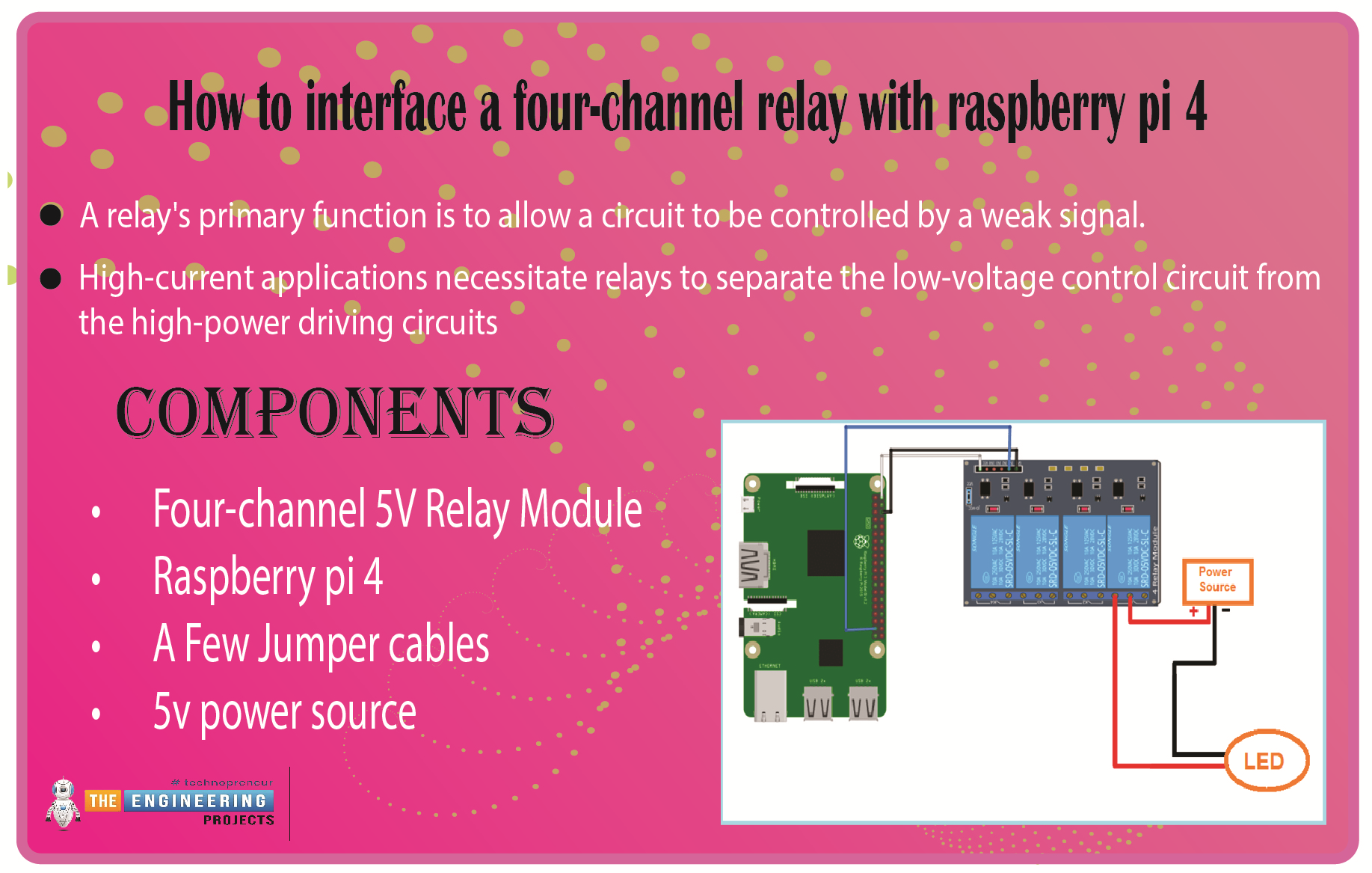
Components
The hardware utilized in this instance is a Pi 4 running Raspbian. All the prerequisites for hardware and software have already been covered, and you can find them in the Raspberry Pi Introduction; other than that, we need:
1000µF capacitor
MCP3008
Joystick Module
LM324 Op-amp IC
1KΩ resistor
LED
2.2KΩ resistor
Jumper wires.
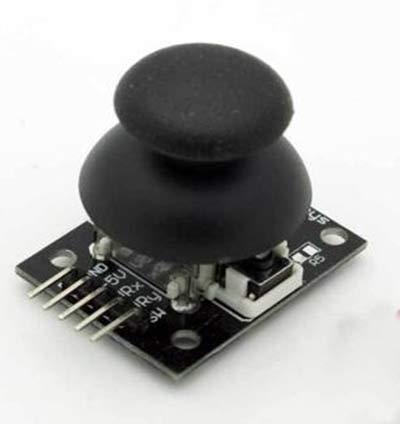
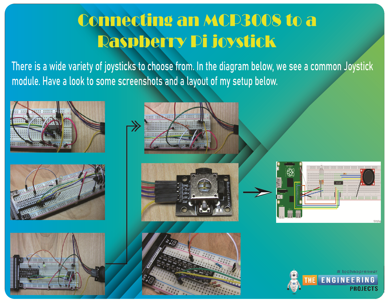
Connecting an MCP3008 to a Raspberry Pi joystick
There is a wide variety of joysticks to choose from. In the diagram below, we see a common Joystick module. The Analog Outputs generated by this Joystick module often fluctuate in response to the orientation of the Joystick. Furthermore, we can determine the movement's direction by analyzing these voltage fluctuations with a microcontroller.
In my setup, pressing down on the Joystick toggles an on/off state for the button, so you may use any standard GPIO pin to connect yours. I'll connect it in the same way as the potentiometers, though.
You'll need to familiarize yourself with the Serial Peripheral Interface bus protocol and understand how to configure it on the Pi before connecting the analog controllers to the Pi with a little chip that employs SPI as a communication medium. You can find excellent guides on accomplishing this on the Pi 4 Spy website.
The SPI bus will be activated on specific GPIO pins, which will be the first thing you learn. In my experience, Method 1 (opening a config panel in Raspbian and choosing the SPI option) worked flawlessly. Then, you'll need to ensure the MCP3008 chip is wired properly. That will serve as the connection between your Joystick and the Pi. Pulse-width modulation is worth investigating if you want to change your RGB LED (PWM) colours.
Circuit diagram
In case you get stuck, I've included some screenshots and a layout of my setup below.
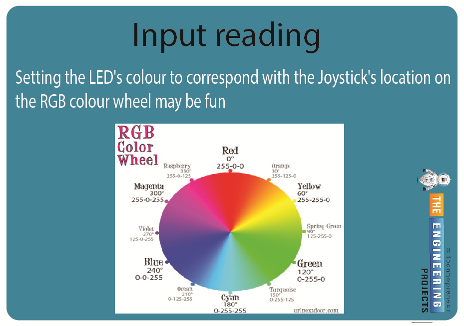
Input reading
Upon enabling SPI, you should have double-checked that pi-spyder was installed. That is required so that the analog device's input may be read. Setting the LED's colour to correspond with the Joystick's location on the RGB colour wheel may be fun. Let's pretend the X-axis is horizontal over Yellow and the Y-axis is vertical over Orange.
Code
import math
import RPi.GPIO as GPIO
import spidev
# Open SPI bus
spi = spidev.SpiDev()
spi.open(0, 0)
# Define sensor channels (3 to 7 are unused)
mcp3008_switch_channel = 0
mcp3008_x_voltage_channel = 1
mcp3008_y_voltage_channel = 2
# Define RGB channels
red_led = 36
green_led = 31
blue_led = 37
def read_spi_data_channel(channel):

adc = spi.xfer2([1, (8+channel) << 4, 0])
return ((adc[1] & 3) << 8) + adc[2]
def convert_coordinates_to_angle(x, y, center_x_pos, center_y_pos):
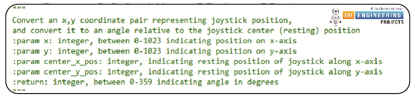
dx = x - center_x_pos
dy = y - center_y_pos
rads = math.atan2(-dy, dx)
rads %= 2 * math.pi
return math.degrees(rads)
def adjust_angle_for_perspective_of_current_led(angle, led):

led_peak_angle = 90 if led == 'R' else (210 if led == 'B' else 330)
return ((angle - led_peak_angle) + 360) % 360
def calculate_next_pwm_duty_cycle_for_led(angle, led):
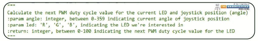
angle = adjust_angle_for_perspective_of_current_led(angle, led)
if 120 < angle < 240:
return 0
elif angle <= 120:
return 100 - (angle * (100 / 120.0))
else:
return 100 - ((360 - angle) * (100 / 120.0))
def is_joystick_near_center(x, y, center_x_pos, center_y_pos):
dx = math.fabs(x - center_x_pos)
dy = math.fabs(y - center_y_pos)
return dx < 20 and dy < 20
def main():
# Center positions when Joystick is at rest
center_x_pos = 530
center_y_pos = 504
GPIO.setmode(GPIO.BOARD)
GPIO.setup([red_led, green_led, blue_led], GPIO.OUT, initial=GPIO.LOW)
pwm_r = GPIO.PWM(red_led, 300)
pwm_g = GPIO.PWM(green_led, 300)
pwm_b = GPIO.PWM(blue_led, 300)
pwm_instances = [pwm_r, pwm_g, pwm_b]
for p in pwm_instances:
p.start(0)
try:
while True:
# If the joystick switch is pressed down, turn off the LEDs
switch = read_spi_data_channel(mcp3008_switch_channel)
if switch == 0:
for p in pwm_instances:
p.ChangeDutyCycle(0)
continue
# Read the joystick position data
x_pos = read_spi_data_channel(mcp3008_x_voltage_channel)
y_pos = read_spi_data_channel(mcp3008_y_voltage_channel)
# If Joystick is at rest in the center, turn on all LEDs at max
if is_joystick_near_center(x_pos, y_pos, center_x_pos, center_y_pos):
for p in pwm_instances:
p.ChangeDutyCycle(100)
continue
# Adjust the duty cycle of LEDs based on the joystick position
angle = convert_coordinates_to_angle(x_pos, y_pos, center_x_pos, center_y_pos)
pwm_r.ChangeDutyCycle(calculate_next_pwm_duty_cycle_for_led(angle, 'R'))
pwm_g.ChangeDutyCycle(calculate_next_pwm_duty_cycle_for_led(angle, 'G'))
pwm_b.ChangeDutyCycle(calculate_next_pwm_duty_cycle_for_led(angle, 'B'))
# print("Position : ({},{}) -- Angle : {}".format(x_pos, y_pos, round(angle, 2)))
except KeyboardInterrupt:
pass
finally:
for p in pwm_instances:
p.stop()
spi.close()
GPIO.cleanup()
if __name__ == '__main__':
main()
So that these methods' input, output, and goals are as apparent as possible, I've put in more effort than normal to comment on the code.
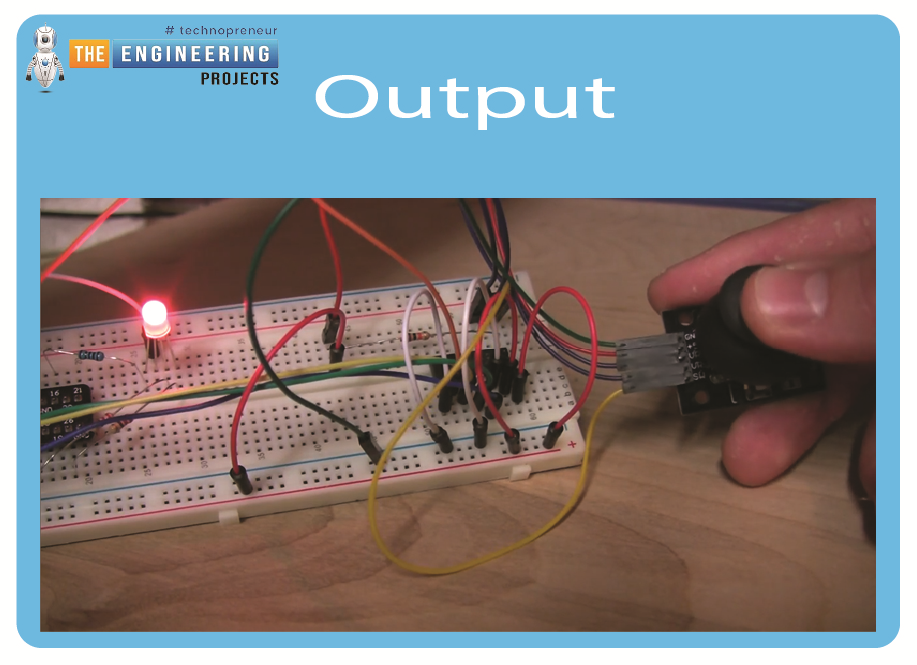
Output
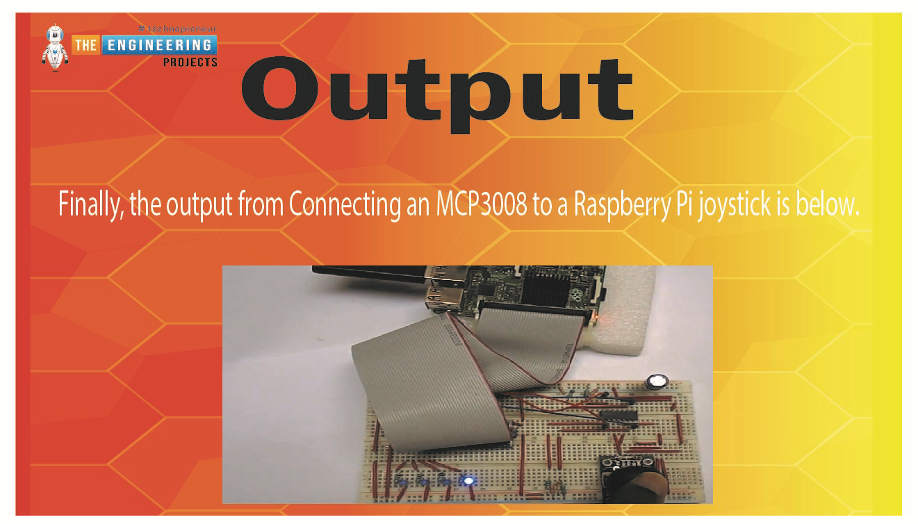
Using OP-amp IC to interface the Joystick to pi 4
Both the X and Y axes are in use. A potentiometer, or "pot," is attached to each axis of the JOY STICK. Rx and Ry are the resulting midpoints of these pots. It follows that Ry and Rx are the movable centers of these kettles. While the Joystick is idle, Rx and Ry serve as voltage dividers.
The voltage at the Rx pin shifts as the Joystick is pushed along the horizontal axis. Similarly, the value at the Ry pin shifts as the device is tilted or turned vertically. The Joystick can be moved in four directions, with two ADC outputs. The voltage at each pin increases or decreases in response to the stick's orientation changes.
As is well-known, Raspberry Pi lacks any built-in Analog Digital Converter hardware. The Pi would be unable to recognize this module if it were attached directly. We shall employ comparators based on operational amplifiers to verify the voltage outputs. These OP-Amps send signals to the Raspberry Pi, and the Pi uses those signals to turn on and off the LEDs. Here, we've implemented a set of four LEDs to represent the four possible Joystick orientations. Please view the accompanying demonstration video.
All 17 GPIO pins have a maximum voltage rating of +3.3V, meaning that any outputs from the Op-amps must be less than that. We needed an op-amp that could operate at 3V, and the LM324 met both requirements. This IC's pins are a good match for the Raspberry Pi's GPIO connectors.
An explanation of operational amplifier circuits.
It has been said that operational amplifiers are the "workhorse" of analog circuits. The LM358 and the LM741 are widely utilized as the most popular varieties of Op-Amp IC. Many functions, such as an amplifier, integrators, differentiators, summers, voltage followers, and more, can be achieved with a single operational amplifier (Op-Amp) by altering the circuitry. Below is a list compiled by Circuit Digest of many Op-amp Circuits, each of which includes a tidy circuit diagram and a practical DIY hardware description to help you learn all about operational amplifiers.

General Operating Conditions of an Operating Amplifier
When utilized in Open-loop mode, the Operational Amplifier (or "Op-amp" for short) can be a perfect amplifier with a typical DC gain of over 100,000 or 100dB.
In its most fundamental form, an operational amplifier (Op-amp) is a three-terminal device with two inputs and a single output (excluding power connections).
The power supply for an operational amplifier can be either a single DC voltage or a pair of supplies, one positive (+V) and one negative (-V).
There can be "no current that flows through either of its two inputs" because of the operational amplifier's zero input offset voltage, V1 = V2, and its infinite input impedance, Z = infinity.
Also, the output impedance of an operational amplifier is zero (Z = 0).
Differential amplifiers, or op-amps, are voltage-sensing amplifiers that magnify the voltage difference between their input terminals by a fixed factor called Gain ( A ).
Sometimes called "Open-loop Gain," (A) is a common measure of an amplifier's effectiveness.
This open-loop gain can be considerably reduced and controlled by connecting the op-output amp to one of its input terminals to close the loop.
There are two common ways to wire operational amplifiers, known as inverting and non-inverting.
LM324 circuit diagram
The LM324 IC includes four OP-AMP comparators to identify Joystick's four possible inputs. Here is the LM324 IC schematic straight from the datasheet.

The following circuit diagram shows the components that make up the Joystick module and the connections that allow it to communicate with the Raspberry Pi. All four comparators within the LM324 are denoted by the U1:A, U1:B, U1:C, and U1:D pins. In the circuit schematic, we have labelled the LM324 IC's comparator pins so that you can easily identify which one goes to which comparator.
Working Explanation
We have OP-AMP1 (or U1:A) and OP-AMP2 (or U1:B) for sensing Joystick motion in the Y axis, and OP-AMP3 (or U1:C) and OP-AMP4 (or U1:D) for sensing Joystick motion in the X axis.
OP-AMP1 picks up on the Y-axis downward movement of the Joystick:
The 2.3V (produced by a voltage divider circuit consisting of 1K and 2.2K) is attached to the negative electrode of comparator U1:A, while the positive terminal is wired to Ry. There is an increase in Ry voltage as the Joystick is moved downward along its Y axis. If the input voltage exceeds 2.3V, the OP-AMP will output +3.3V at the output Pin. In response to the OP-HIGH AMP's logic output, the Raspberry Pi will turn on and off an LED.
Joystick up, Y-axis, is detected by OP-AMP2:
The 1.0V (supplied by a voltage divider circuit consisting of 2.2K and 1K) is connected to the comparator U1: negative B's terminal, while the positive terminal is wired to Ry. As you raise the Joystick's Y axis, the voltage on Ry will drop. The OP-AMP output will go Low when this voltage falls below 1.0V. When the Raspberry Pi sees the LOW logic output from the OP-AMP, it will respond by turning on and off an LED.
With OP-AMP3, X-axis joystick motion to the left is detected:
The comparator U1: negative C's terminal is given 2.3V (1K and 2.2K via a voltage divider circuit), while the positive terminal is linked to Rx. Increasing Rx voltage occurs when the Joystick is moved to the left along its x-axis. If the input voltage exceeds 2.3V, the OP-AMP will output +3.3V at the output Pin. In response to the OP-HIGH AMP's logic output, the Raspberry Pi will turn on and off an LED.
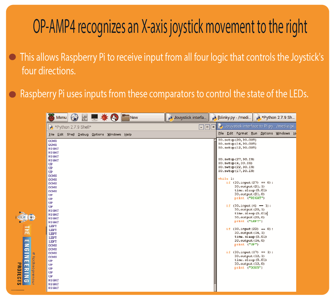
OP-AMP4 recognizes an X-axis joystick movement to the right:
U1:4's negative terminal is given 1.0V (through a voltage divider circuit of 2.2K and 1K), while the positive terminal is linked to Rx. Rx voltage drops as the Joystick is moved to the right along its x-axis. The OP-AMP output will go Low when this voltage falls below 1.0V. When the Raspberry Pi sees the LOW logic output from the OP-AMP, it will respond by turning on and off an LED.
This allows Raspberry Pi to receive input from all four logic that controls the Joystick's four directions. Raspberry Pi uses inputs from these comparators to control the state of the LEDs. Here are the terminal outputs from our Raspberry Pi program, which also prints the Joystick's orientation to the screen.
A Python script is available below. The code is simple, and the comments make it easy to understand.
Complete code
import RPi.GPIO as IO # calling for the header file, which helps in using GPIOs of PI
import time # we are calling for time to provide delays in the program
IO.setwarnings(False) # do not show any warnings
IO.setmode (IO.BCM) #programming the GPIO by BCM PINs (like PIN29 as GPIO5)
IO.setup(21,IO.OUT) # initialize GPIO21 as an output
IO.setup(20,IO.OUT)
IO.setup(16,IO.OUT)
IO.setup(12,IO.OUT)
IO.setup(27,IO.IN) # initialize GPIO27 as an input
IO.setup(4,IO.IN)
IO.setup(22,IO.IN)
IO.setup(17,IO.IN)
while 1:
if (IO.input(27) == 0): #If GPIO 27 goes low toggle LED on 21pin and print RIGHT
IO.output(21,1)
time.sleep(0.01)
IO.output(21,0)
print ("RIGHT")
if (IO.input(4) == 1): #If GPIO 4 goes high toggle LED on 20pin and print LEFT
IO.output(20,1)
time.sleep(0.01)
IO.output(20,0)
print ("LEFT")
if (IO.input(22) == 0): #If GPIO 22 goes low toggle LED on 16pin and print UP
IO.output(16,1)
time.sleep(0.01)
IO.output(16,0)
print ("UP")
if (IO.input(17) == 1): #If GPIO 17 goes high toggle LED on 12pin and print DOW
IO.output(12,1)
time.sleep(0.01)
IO.output(12,0)
print ("DOWN")
Output
Conclusion
As we've seen in this guide, the Pi 4 computer lacks an analog input. The only data it can process is digital. Contrast it with the plentiful analog inputs of common microcontrollers like Arduino, AVR, or PIC. Many sensors produce analog outputs; therefore, we need a method to make the Pi analog-friendly. To that end, we have considered two alternatives. Connecting an MCP3008 microcontroller and an LM324 operational amplifier integrated circuit creates a "bridge" between analog and digital signals. If you have any questions regarding the setup or the code, or if you run into any problems, please let me know in the comments, and I'll do my best to help. The next article will teach you how to use a Raspberry Pi 4 to operate a relay board with four independent outputs.