


Sending SMS & Call with GSM Module and Raspberry Pi 4


Greetings, and welcome to another tutorial in our series on the raspberry pi 4 Python programming. The previous guide covered the basics of transmitting data over the radio using the nrf24l01 chip in Pi 4. We also learned about interfacing Arduino and raspberry pi 4 and sending radio signals between the two devices. However, this tutorial will walk you through building a Raspberry Pi-based mobile phone with a microphone and speaker for making and receiving calls and reading text messages (SMS). This Project also serves as a proper GSM Module for the Raspberry Pi interface, with all the necessary Code to run the most fundamental features of any modern smartphone. First, we will understand what gsm is, its architecture and how it works, then we will learn how to program it in our pi 4; therefore, let us begin.
Components:
Raspberry Pi 4
GSM Module
16x2 LCD
4 *4 Keypad
10k pot
Breadboard
Connecting jumper wire
Power supply
Speaker
Microphone
SIM Card
Loudspeaker
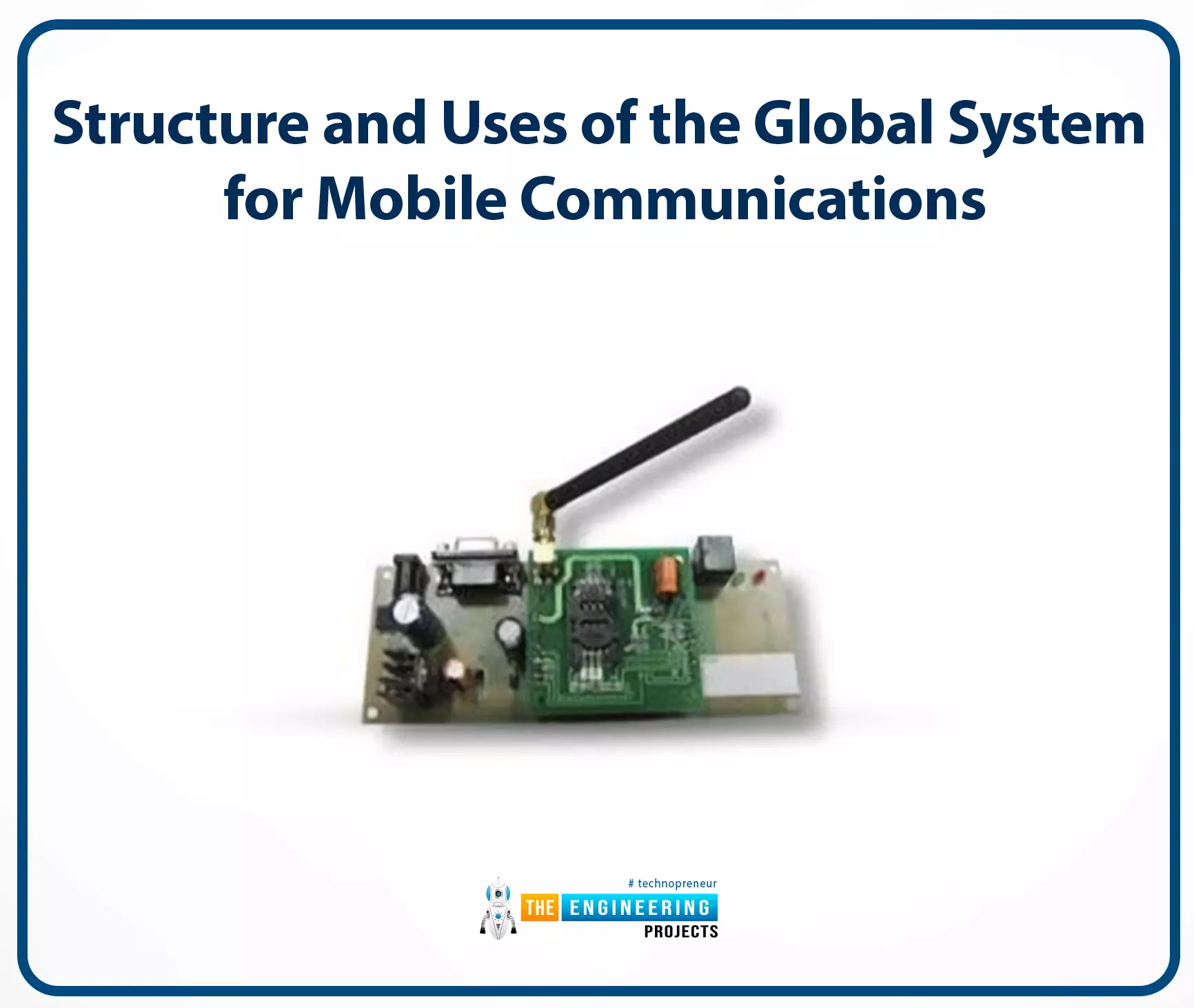
Structure and Uses of the Global System for Mobile Communications
The acronym "GSM" refers to the "global system for mobile communication" and is the name of a type of mobile communication modem (GSM). Bell Labs was responsible for conceptualizing GSM in the 1970s. It's one of the most common forms of mobile communication around the globe. The 850MegaHertz, 900MegaHertz, 1800 Megahertz, and 1900 Megahertz frequency bands are utilized by GSM networks, which are part of an open and digital mobile network used to carry voice and data services.
Using the telecommunications method of multiple time division access (TDMA), GSM technology was created as a digital system. For transmission, a GSM converts analog signals to digital ones, compresses them further and delivers them through a channel sharing bandwidth with two data streams from separate clients. The data rates transported by the digital system range from 64 kilobytes per second to 120 Megabytes per second.
In a GSM network, macro, micro, and umbrella cells coexist. The implementation context determines the specifics of each cell. The macro, micro, and umbrella cell sizes are in use in a GSM network. Each cell may have a different range of coverage depending on the setting.
Time-division multiple access (TDMA) works by giving each user a specific amount of time to transmit on the same frequency. It's flexible, supporting data rates from 64kbps to 120Mbps and allowing for clear voice communications.
Structure of GSM-Based Technologies
The following are the primary components of the GSM architecture.
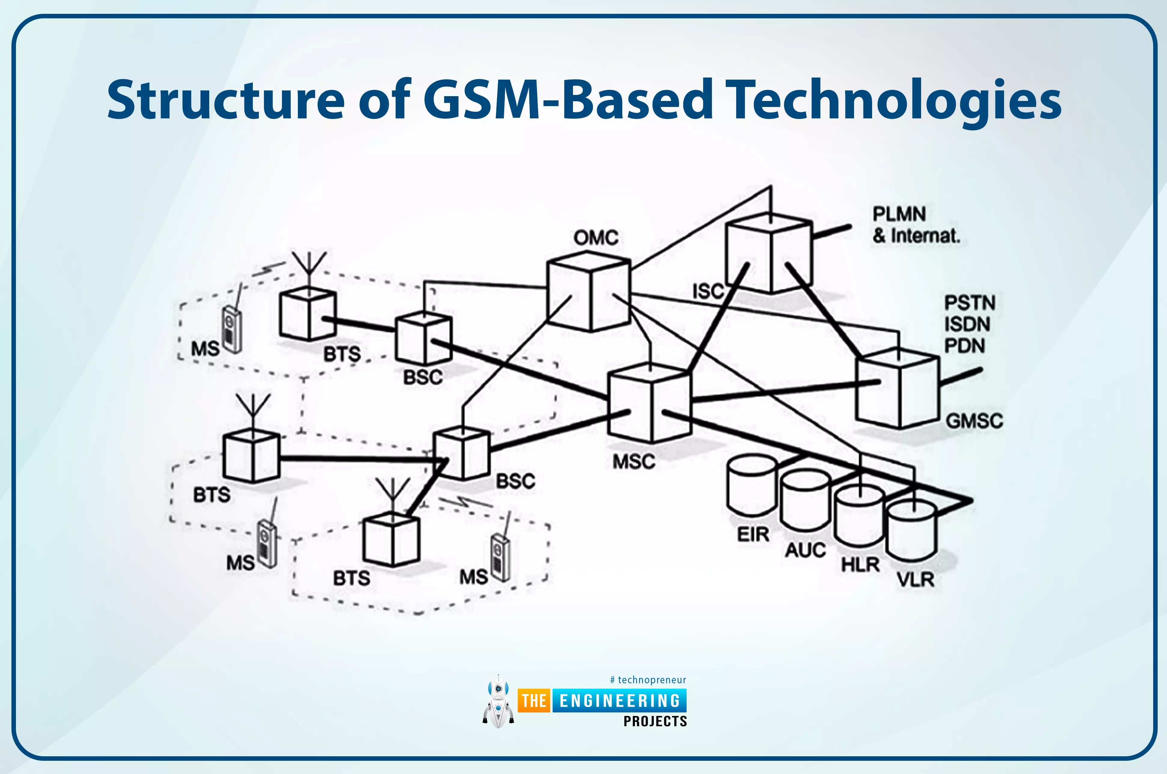
Connectivity and Switching Infrastructure (NSS)
All three of these components—the Base Station (BS), the Mobile Station (MS), and the Operations and Maintenance Subsystem (OSS)—are necessary for proper communication (OSS)
Network Switching Subsystem (NSS)
Each component of the GSM system design contributes to what is collectively called the core system/network. In this case, the mobile network system is primarily controlled and interfaced with via a data network consisting of several different components. Listed below are some of the most crucial elements of the underlying network.
Mobile Switching Centre (MSC)
One of the essential parts of a GSM network is its core network, where the Mobile Switching Center (MSC) resides. This MSC performs the same functions as a common switching node in an ISDN or PSTN. Still, it provides additional features to accommodate mobile users' requirements, such as authentication, registration, inter-MSC handovers, call localization, and routing.
In addition, it gives users an advantage in connecting their mobile phone networks to the PSTN (public switched telephone network) for making and receiving landline calls. To facilitate mobile-to-mobile calls across different networks, interfaces to all other switched telephone networks ( PSTN center servers are given.
Home Location Register (HLR)
Every subscriber's administrative details, including their last known location, are stored in this HLR database. This manner, calls can be routed over the GSM network to the appropriate mobile switch base station. If a call comes in when an operator has their phone turned on, the network can determine which base transmitter station the call is coming from and link it to the correct phone.
When the phone is turned on but not being used, it nevertheless registers to ensure the HLR system is aware of its current location. Each network has a single HLR, which may be physically split across several data centers for practical reasons.
Visitor Location Register (VLR)
To facilitate the VLR's desired services for the individual subscriber, it incorporates data from the HLR network. It is possible to run the visitor coordinates register independently, but it is most commonly implemented as a core component of the MSC. Because of this, getting access is more manageable, and it takes less time overall.
Equipment Identity Register (EIR)
The Equipment Identity Register (EIR) is the part of the network infrastructure in charge of deciding whether or not certain pieces of mobile equipment are allowed access. The International Mobile Equipment Identification (IMEI) numbers uniquely identify each mobile technology work.
This IMEI number is permanently embedded within the mobile device and checked by the network after registration. Depending on the data in the EIR, the mobile phone may be given one of three possible network access states: allowed, banned, or monitored.
Authentication Centre (AuC)
When users insert their SIM card into their phone, the secret key is stored in a secure file known as the AUC (authentication center). The AUC sees the extensive application as a radio channel coding and verification standard.
Gateway Mobile Switching Centre (GMSC)
In the absence of location information for the mobile station (MS), a call placed by a ME terminates with the GMSC (Gateway Mobile Switching Centre). Using the Mobile Subscriber Identifier Service Data Number (MSISDN) and the HLR, the GMSC can locate the specific MSC that has been visited and connect the call to the appropriate location. It's unclear what the "MSC" part of GMSC stands for, as the gateway procedure does not require relating to an MSC.
SMS Gateway (SMS-G)
Both SMS-Gateways are referred to collectively as the SMS gateway in the GSM specifications. The messages passing via these gateways are directed in various ways.
Sending a short message to mobile equipment (ME) requires the usage of the Short Messaging Service Gateway Switching Center. Short messages sent over a mobile network are routed through the SMS Inter-Working Switching Center. While the SMS-primary GMSC's function concerns the GMSC, the SMS-IWMSC serves as a constant endpoint for access to the Short Message Service Centre.
These were the primary nodes in the GSM system's infrastructure. While they frequently shared physical space, the entire middle network would sometimes be broadcast throughout the country. In the event of a failure, it will provide a degree of leeway.
Base Station Subsystem (BSS)
The connection point between the mobile node and the broader network infrastructure. The radio transceivers and protocol management for mobile devices are housed in the Base Transceiver Station. In addition, a Base Station Controller manages the Base Transceiver and serves as a bridge between mobile devices and the mobile switching hub.
The network subsystem handles connectivity between the network and the mobile stations. The Phone Service Switch Centre is the backbone of the Network Subsystem, allowing users to connect to other networks (ISDN, PSTN, etc.). The GSM system's ability to route calls and allow for roaming depends on two additional components, the Home Location Record and the guest Location Record.
In addition, it stores the Equipment Identity Register, which keeps track of all the mobile devices and their associated IMEI numbers. The acronym IMEI refers to the unique identifier for mobile devices worldwide.
In the second generation of GSM network design, the mobile devices communicate with the BSS, or Base Station Subsystem. These components comprise this subsystem, and each will be examined.
Base Transceiver Station (BTS)
As part of a GSM network, the radio Tx, Rx, and their associated antennas make up the base Transceiver Station, which is used for transmitting, receiving, and communicating directly through mobiles. The base station is the central component of each cell, and it communicates with mobile devices using an interface known as the Um interface and related protocols.
Base Station Controller (BSC)
The base station controller (BSC) is employed for the following step back into GSM technology. This controller is typically co-located within one of the base transceiver stations it controls. This controller handles radio resource management, including channel allocation and handover between base station groups. Over the Abis interface, it communicates with the BTSs.
The acceptable radio technology is used by the GSM network's subsystems component in the ground station to ensure that multiple operators can utilize the system at the same time. Each base station can support many operators because each channel can support up to eight users.
The network provider strategically places these to ensure comprehensive coverage. A base station, sometimes known as a "cell," can surround this space. Signals can't be prevented from bleeding into neighbouring cells, and the channels used in one don't transfer to the next.
Mobile Station
Mobile phones include a transceiver, a display, and a CPU, all of which are network-connected and operated using a SIM card. In a GSM mobile transmission medium, the operator monitors and controls the mobile station or mobile equipment, which are most commonly represented by cell phones. Their size has shrunk significantly while their functionality has skyrocketed. The benefit of a much longer interval between charges is still another advantage. Phone hardware and the subscriber identity module (SIM) are two of many components.
A mobile device's hardware consists of its primary components, such as the housing, screen, battery, and electronics used to generate the signal and process the signal receiver before transmission. The IMEI is a unique number assigned to each mobile device. This feature can be permanently programmed into a phone throughout its manufacturing process. During the registration process, the network accesses this database to see if the device has been flagged as stolen.
A user's identity on the network is stored in the information contained in their SIMcard. It also includes other data, such as the IMSI number. With this IMSI stored in the Sim, the phone user could easily switch phones by swapping SIM cards. As a result, if switching to a new mobile phone were simple and didn't require a unique phone number, more people would do it, generating more revenue for network operators and contributing to GSM's overall economic triumph.
Operation and Support Subsystem (OSS)
The OSS is an integral aspect of any functional GSM network. The NSS and BSC parts are linked here. The GSM network and BSS traffic load are the primary areas of focus for this OSS. It is worth noting that some preservation responsibilities are relocated to the base station controller to lower the maintenance expense of the system when the amount of BS increases through the consumer population growth.
The 2G GSM network architecture is predicated on a rational functioning method. This approach is remarkably straightforward compared to today's mobile network architectures, which rely on software-defined units to facilitate highly adaptable operations. However, the 2G GSM architecture will show how the necessary voice and essential operational functions are organized.
Specifications of a GSM Module
The following are some of the functions provided by the GSM module.
Enhanced spectrum efficiency
Features including "international roaming," "integrated services digital network" (ISDN) compatibility, and "support for future services" are also included.
High-quality voice communications; encrypted phone conversations;
Features like a programmable alarm clock, high-quality voice communication, a fixed calling number, a real-time clock, and the ability to send and receive SMS messages are all standard on modern smartphones (SMS)
As a result of its rigorous security measures, the GSM system is currently the safest available for use in the telecommunications industry. Call privacy and subscriber anonymity for GSM users are only protected during transmission, but this is still a massive step toward attaining end-to-end security.
GSM Modem
In either its mobile phone or modem form, a Global System for Mobile Communications (GSM) modem enables two computers or processors to connect across a network. A SIM card is needed to run a GSM modem, and it can only be used within the coverage area the network provider has paid for. It has serial, USB, and Bluetooth connectivity options for linking to a personal computer.
Any regular GSM cell phone can double as a GSM modem if you have a suitable cable and driver installed on your PC. It would be best if you used a GSM modem instead of a GSM cell phone. The GSM modem is helpful in many devices, including POS terminals, inventory management systems, surveillance cameras, weather stations, and GPRS-mode remote data loggers.
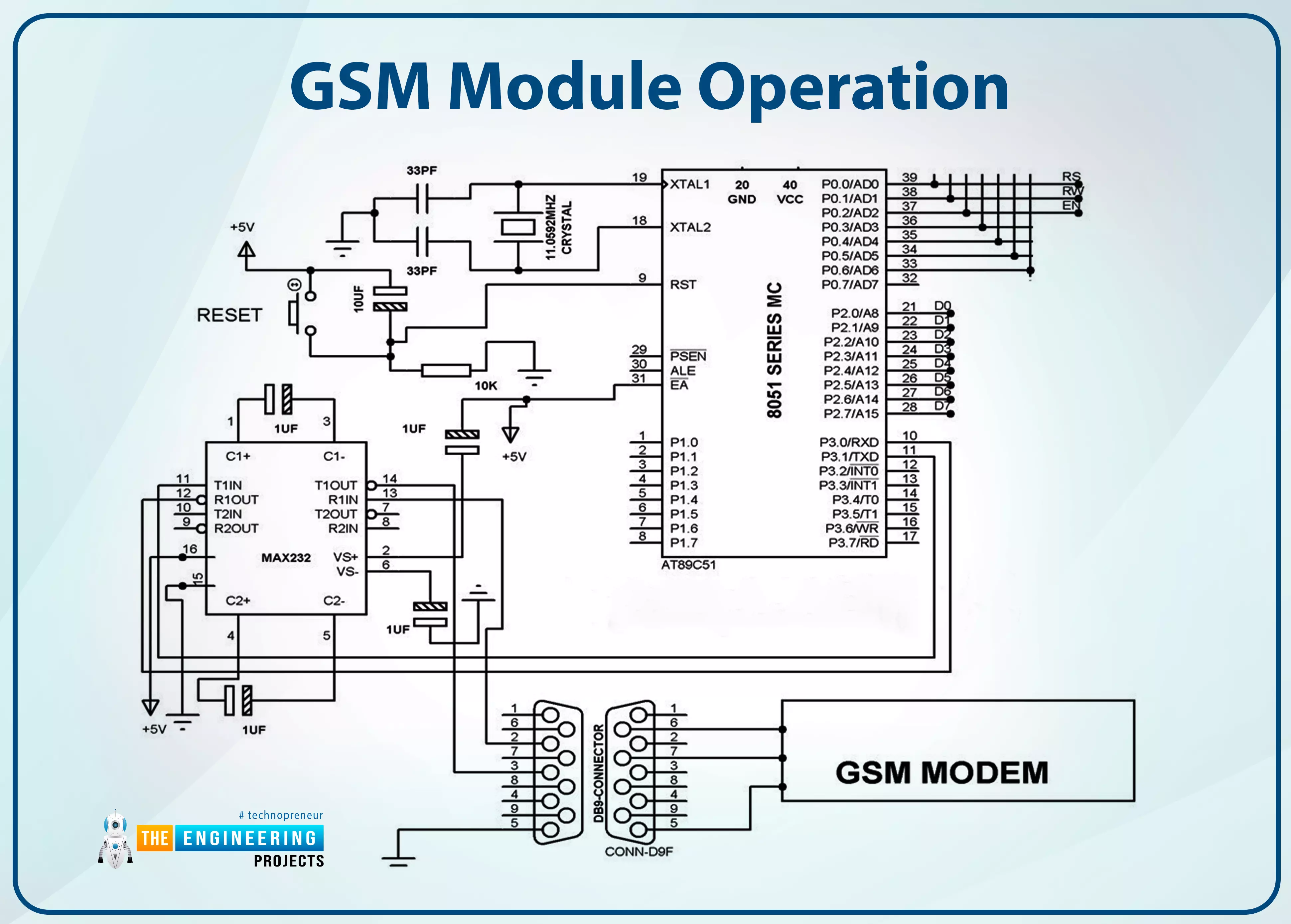
GSM Module Operation
Below is a circuit showing how to connect a GSM modem to the MC using the level-shifting IC Max232. When a numeric command is received by short message service (SMS) from any mobile device, the SIM card-mounted GSM modem transfers that information to the MC via serial connection. The GSM modem is programmed to respond to the order "STOP" by producing an MC output, the point which is utilized to deactivate the ignition switch.
If the input is driven low, the GSM modem will send a predetermined message (in this case, "ALERT") to the user. A 162 LCD screen displays the entirety of the procedure.
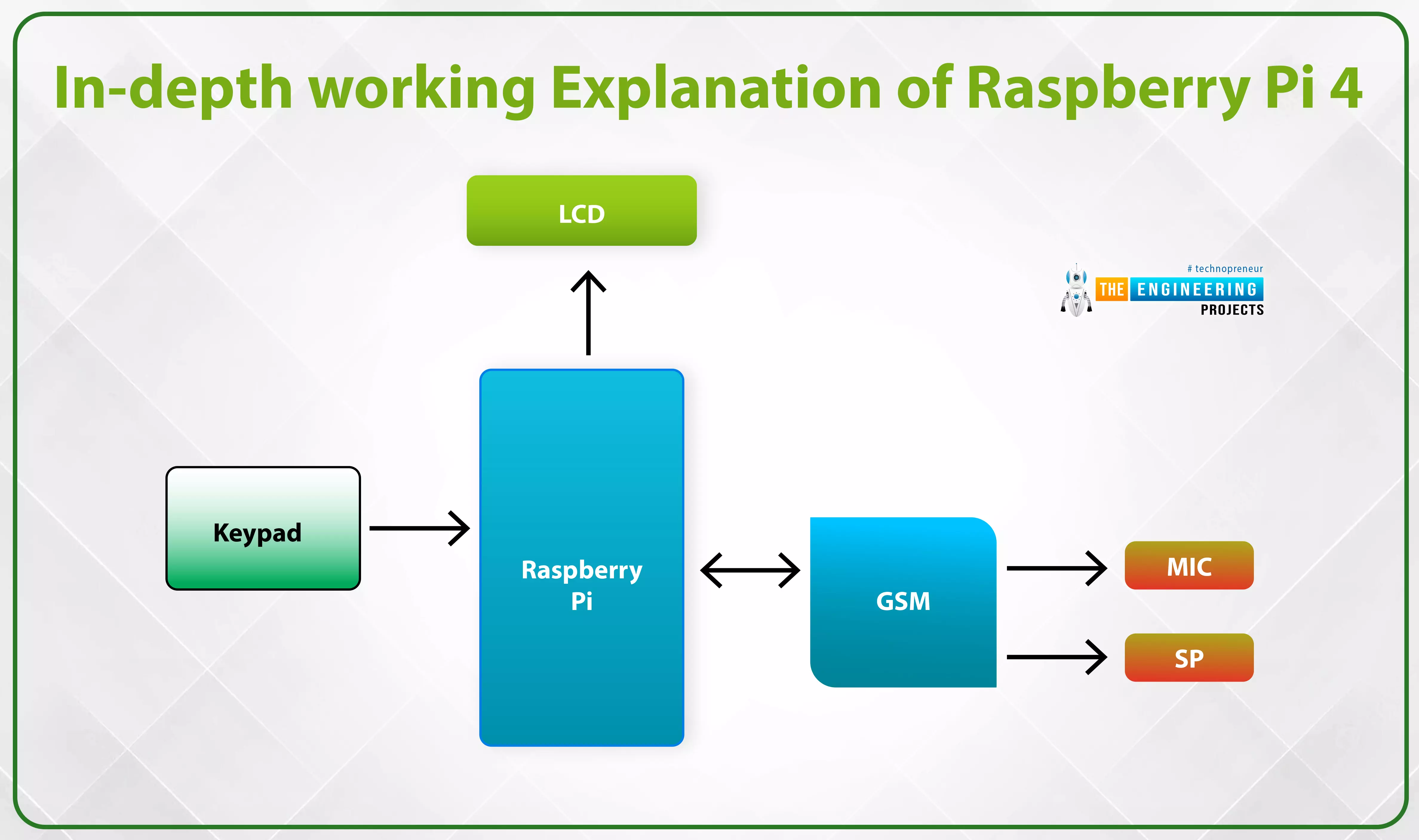
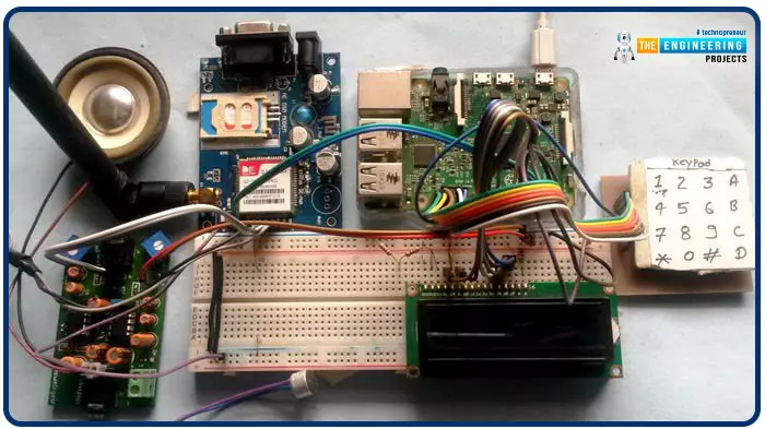
In-depth working Explanation of raspberry pi 4
We have utilized a GSM module and a Raspberry Pi 4 to manage the entire system and interface its many parts in this Project. You can input data of any kind, including phone numbers, text messages, and phone calls, read and respond to text messages, and more, using a 4x4 alphanumeric keypad. The SIM900A GSM module connects mobile phones to wireless networks for making and receiving calls and sending and receiving text messages. We've integrated a microphone, a loudspeaker for making and receiving voice calls, and a 16 * 2 liquid crystal displays information like menu options and alarms.
With alphanumeric input, you can use the same keyboard to type in both numbers and letters. For the Code we used to allow alphabets in addition to numbers in this method, scroll down to the "Code in Code" section.
It's simple to put this plan into action. The alphanumeric keypad is used for all functions. Below you'll find a link to the complete Code and a demonstration video. This section will elaborate on the four aspects of the listed projects.
The Pi 4 Mobile Phone Four Main Attributes
Make Call
The Pi 4 phone we built requires us to press the letter "C" and provide the cellphone number we wish to call. We'll use an alphanumeric keyboard to enter the number. Once the correct number has been entered, we must hit "C" again. The AT command is now processed by pi 4 to connect the call to a specified number.
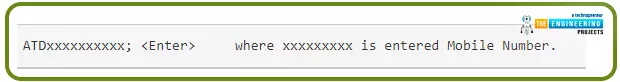
ATDxxxxxxxxxx; <Enter> where xxxxxxxxx is entered Mobile Number.
Receive Call
Answering a phone call is simple. When a call comes into the SIM number stored in the GSM Module of your system, the LCD will display the message "Incoming..." along with the caller's number. All that's left to do is hit the 'A' key to answer the call. Pi 4 will send the following command to the GSM Module when the "A" button is pressed:

ATA <enter>
Transmit SMS
Pressing "D" on our Raspberry Pi phone allows us to send a text message. To whom (or what) should we address the SMS message that the system has just requested? Once the number has been entered, pressing "D" again will prompt the LCD to request a message. To send an SMS, enter the message using the keypad as you would with any other mobile device, and then hit the 'D' key again. Raspberry Pi can send SMS with the following command:
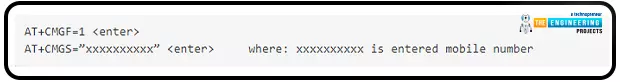
AT+CMGF=1 <enter>
AT+CMGS=”xxxxxxxxxx” <enter> where: xxxxxxxxxx is entered mobile number
Receive and Read SMS
Even this component is easy to use. Here, the SIM card is used to receive SMS messages from the GSM. The Raspberry Pi also keeps a close eye on the UART SMS signal. New notes are shown by the LCD displaying the text "New message," and reading them is as simple as pressing the "B" key. This is an SMS Received signal:
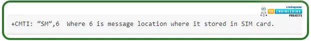
+CMTI: "SM," 6 Where 6 is the message location where it is stored in the SIM card.
When the RPi detects the 'SMS received' signal, it will get the SMS storage location and instruct the Global system for mobile to read the message. Moreover, the LCD will flash the words "New Message" in a prominent location.
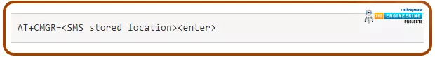
AT+CMGR=<SMS stored location><enter>
The GSM now delivers the saved message to the Raspberry Pi, and the Pi, having extracted the primary SMS, shows it on the LCD. When it comes to MIC and Speaker, there is no secret code.
Detailed Circuit Layout and Explanation
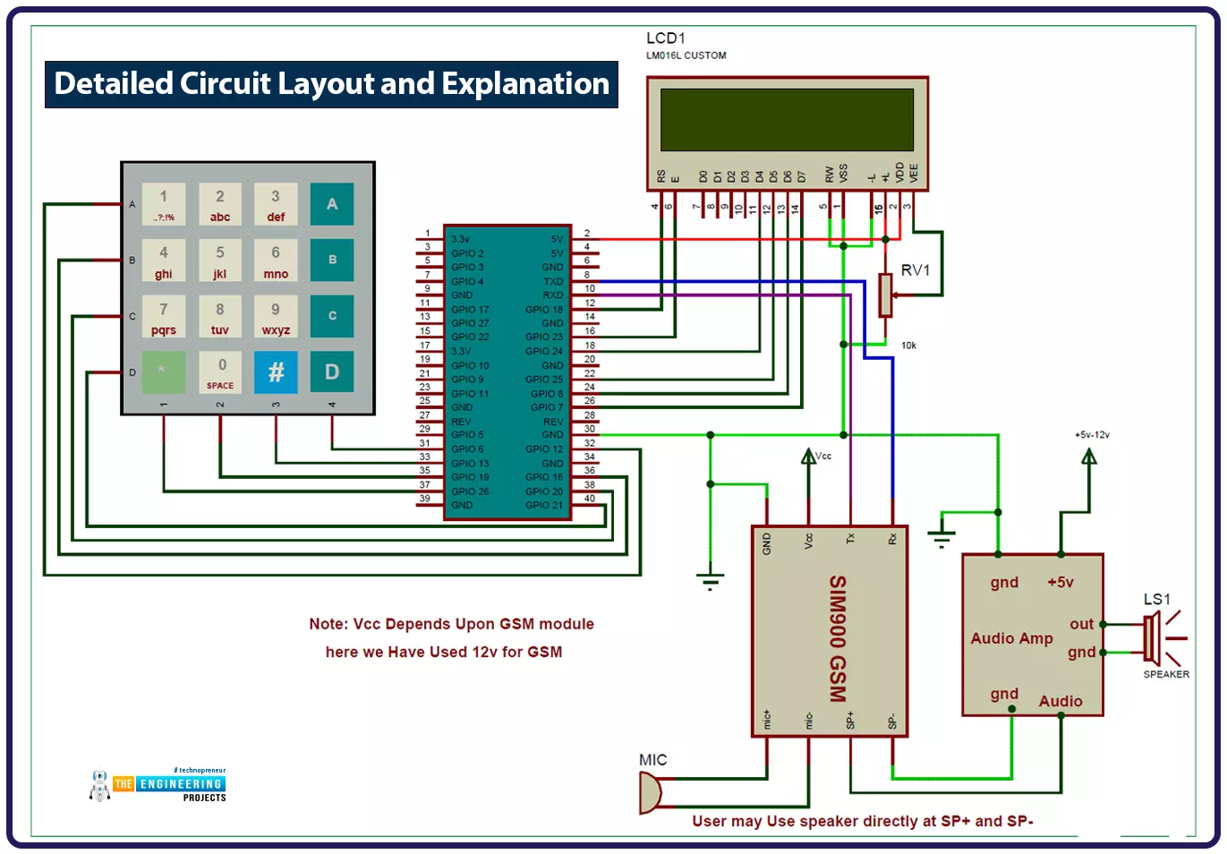
The GPIO pins of the Raspberry Pi are wired to the RS, EN, D4, D5, D6, and D7 pins of the 16 * 2 liquid crystal display. A direct connection is made between the GSM module's Rx and Tx pins and the Raspberry Pi's Tx and Rx pins. Connectors R1, R2, R3, and R4 of a 4 * 4 keypad are connected to GPIOs 12, 16, 20, and 21, whereas pins C1, C2, C3, and C4 are connected to GPIOs 26, 19, 13, and 6. If you want to boost the audio volume from the GSM Module, you can join the microphone directly to the mic+ and mic- pins and the loudspeaker to the sp+ and sp- pins. The loudspeaker can be connected directly to the GSM module without using the Audio Amplifier circuit.
Explanation of the Code
This Pi 4 mobile phone's programming interface may be challenging to novices—the programming language of choice for this Project is Python.
Here, we define the keypad() function to be used with a basic numeric keypad. We've also added a def alpha keypad(): for typing alphabets so that you may use the same keypad for both purposes. To make it compatible with the Arduino keypad library, we've given this keypad a wide range of new capabilities. This keypad only takes 10 presses to enter a whole string of text or a numeric value.
For example, if we push key 2 (abc2) once, the LCD will display the letter 'a.' If we press it again, the letter 'b' will take its place, and if we hit it three more times, the letter 'c' will appear in the same spot. After holding down a key for a short time, the LCD pointer will advance to the following available location. We can now proceed to the next character or number. Any other keys can be processed in the same way.
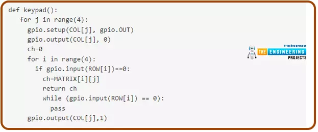
def keypad():
for j in range(4):
gpio.setup(COL[j], gpio.OUT)
gpio.output(COL[j], 0)
ch=0
for i in range(4):
if gpio.input(ROW[i])==0:
ch=MATRIX[i][j]
return ch
while (gpio.input(ROW[i]) == 0):
pass
gpio.output(COL[j],1)
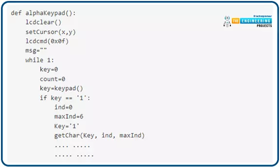
def alphaKeypad():
lcdclear()
setCursor(x,y)
lcdcmd(0x0f)
msg=""
while 1:
key=0
count=0
key=keypad()
if key == '1':
ind=0
maxInd=6
Key='1'
getChar(Key, ind, maxInd)
.... .....
..... .....
To begin, we have declared the pins for the liquid crystal display, the keypad, and other components, as well as included the necessary libraries in this python script:
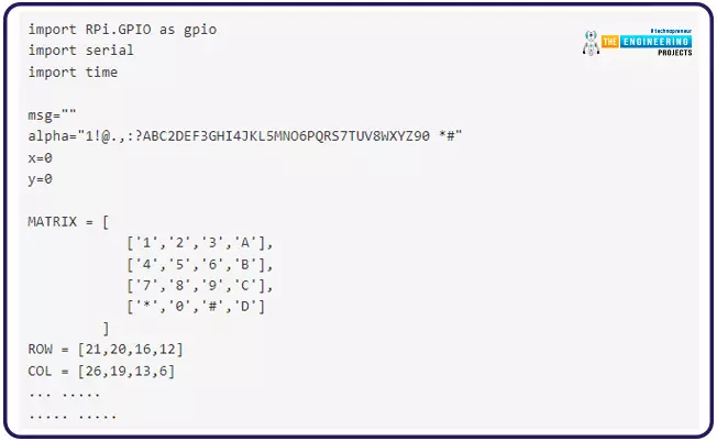
import RPi.GPIO as gpio
import serial
import time
msg=""
alpha="1!@.,:?ABC2DEF3GHI4JKL5MNO6PQRS7TUV8WXYZ90 *#"
x=0
y=0
MATRIX = [
['1','2','3','A'],
['4','5','6','B'],
['7','8','9','C'],
['*','0','#','D']
]
ROW = [21,20,16,12]
COL = [26,19,13,6]
... .....
..... .....
The pins need to be pointed in the proper direction.
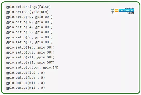
gpio.setwarnings(False)
gpio.setmode(gpio.BCM)
gpio.setup(RS, gpio.OUT)
gpio.setup(EN, gpio.OUT)
gpio.setup(D4, gpio.OUT)
gpio.setup(D5, gpio.OUT)
gpio.setup(D6, gpio.OUT)
gpio.setup(D7, gpio.OUT)
gpio.setup(led, gpio.OUT)
gpio.setup(buz, gpio.OUT)
gpio.setup(m11, gpio.OUT)
gpio.setup(m12, gpio.OUT)
gpio.setup(button, gpio.IN)
gpio.output(led , 0)
gpio.output(buz , 0)
gpio.output(m11 , 0)
gpio.output(m12 , 0)
To begin Serial communication, follow the steps below.
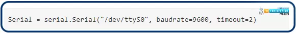
Serial = serial.Serial("/dev/ttyS0", baudrate=9600, timeout=2)
We must now create a liquid crystal display driving function. The def lcdcmd(ch): and def lcdwrite(ch): functions are used to deliver commands and data to the LCD, respectively. The liquid crystal display may also be cleared with def lcdclear(), the cursor position can be set with def setCursor(x,y), and a string can be sent to the liquid crystal display with def lcdprint(Str).
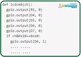
def lcdcmd(ch):
gpio.output(RS, 0)
gpio.output(D4, 0)
gpio.output(D5, 0)
gpio.output(D6, 0)
gpio.output(D7, 0)
if ch&0x10==0x10:
gpio.output(D4, 1)
.... .....
..... ....
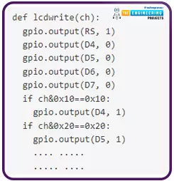
def lcdwrite(ch):
gpio.output(RS, 1)
gpio.output(D4, 0)
gpio.output(D5, 0)
gpio.output(D6, 0)
gpio.output(D7, 0)
if ch&0x10==0x10:
gpio.output(D4, 1)
if ch&0x20==0x20:
gpio.output(D5, 1)
.... .....
..... ....
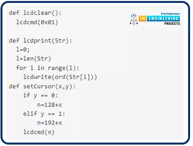
def lcdclear():
lcdcmd(0x01)
def lcdprint(Str):
l=0;
l=len(Str)
for i in range(l):
lcdwrite(ord(Str[i]))
def setCursor(x,y):
if y == 0:
n=128+x
elif y == 1:
n=192+x
lcdcmd(n)
Next, we'll need to code some features for interacting with text messages, phone calls, and incoming calls.
The call is placed using the function def call():. Also, the LCD can display the receiving message and number via the function def receiveCall(data):. Finally, the call is answered with def attendCall():.
The message is composed and sent using the alphaKeypad() method, accessed via the def sendSMS(): function. The SMS is received, and its location is retrieved using the def receive SMS(data) function. And finally, the LCD gets updated with the message thanks to def readSMS(index:).
All of the operations mentioned above are included in the Code that follows.
import RPi.GPIO as gpio
import serial
import time
msg=""
# 0 7 11 15 19 23 27 32 36 414244 ROLL45
alpha="1!@.,:?ABC2DEF3GHI4JKL5MNO6PQRS7TUV8WXYZ90 *#"
x=0
y=0
MATRIX = [
['1','2','3','A'],
['4','5','6','B'],
['7','8','9','C'],
['*','0','#','D']
]
ROW = [21,20,16,12]
COL = [26,19,13,6]
moNum=['0','0','0','0','0','0','0','0','0','0']
m11=17
m12=27
led=5
buz=26
button=19
RS =18
EN =23
D4 =24
D5 =25
D6 =8
D7 =7
HIGH=1
LOW=0
gpio.setwarnings(False)
gpio.setmode(gpio.BCM)
gpio.setup(RS, gpio.OUT)
gpio.setup(EN, gpio.OUT)
gpio.setup(D4, gpio.OUT)
gpio.setup(D5, gpio.OUT)
gpio.setup(D6, gpio.OUT)
gpio.setup(D7, gpio.OUT)
gpio.setup(led, gpio.OUT)
gpio.setup(buz, gpio.OUT)
gpio.setup(m11, gpio.OUT)
gpio.setup(m12, gpio.OUT)
gpio.setup(button, gpio.IN)
gpio.output(led , 0)
gpio.output(buz , 0)
gpio.output(m11 , 0)
gpio.output(m12 , 0)
for j in range(4):
gpio.setup(COL[j], gpio.OUT)
gpio.setup(COL[j],1)
for i in range (4):
gpio.setup(ROW[i],gpio.IN,pull_up_down=gpio.PUD_UP)
Serial = serial.Serial("/dev/ttyS0", baudrate=9600, timeout=2)
data=""
def begin():
lcdcmd(0x33)
lcdcmd(0x32)
lcdcmd(0x06)
lcdcmd(0x0C)
lcdcmd(0x28)
lcdcmd(0x01)
time.sleep(0.0005)
def lcdcmd(ch):
gpio.output(RS, 0)
gpio.output(D4, 0)
gpio.output(D5, 0)
gpio.output(D6, 0)
gpio.output(D7, 0)
if ch&0x10==0x10:
gpio.output(D4, 1)
if ch&0x20==0x20:
gpio.output(D5, 1)
if ch&0x40==0x40:
gpio.output(D6, 1)
if ch&0x80==0x80:
gpio.output(D7, 1)
gpio.output(EN, 1)
time.sleep(0.005)
gpio.output(EN, 0)
# Low bits
gpio.output(D4, 0)
gpio.output(D5, 0)
gpio.output(D6, 0)
gpio.output(D7, 0)
if ch&0x01==0x01:
gpio.output(D4, 1)
if ch&0x02==0x02:
gpio.output(D5, 1)
if ch&0x04==0x04:
gpio.output(D6, 1)
if ch&0x08==0x08:
gpio.output(D7, 1)
gpio.output(EN, 1)
time.sleep(0.005)
gpio.output(EN, 0)
def lcdwrite(ch):
gpio.output(RS, 1)
gpio.output(D4, 0)
gpio.output(D5, 0)
gpio.output(D6, 0)
gpio.output(D7, 0)
if ch&0x10==0x10:
gpio.output(D4, 1)
if ch&0x20==0x20:
gpio.output(D5, 1)
if ch&0x40==0x40:
gpio.output(D6, 1)
if ch&0x80==0x80:
gpio.output(D7, 1)
gpio.output(EN, 1)
time.sleep(0.005)
gpio.output(EN, 0)
# Low bits
gpio.output(D4, 0)
gpio.output(D5, 0)
gpio.output(D6, 0)
gpio.output(D7, 0)
if ch&0x01==0x01:
gpio.output(D4, 1)
if ch&0x02==0x02:
gpio.output(D5, 1)
if ch&0x04==0x04:
gpio.output(D6, 1)
if ch&0x08==0x08:
gpio.output(D7, 1)
gpio.output(EN, 1)
time.sleep(0.005)
gpio.output(EN, 0)
def lcdclear():
lcdcmd(0x01)
def lcdprint(Str):
l=0;
l=len(Str)
for i in range(l):
lcdwrite(ord(Str[i]))
def setCursor(x,y):
if y == 0:
n=128+x
elif y == 1:
n=192+x
lcdcmd(n)
def keypad():
for j in range(4):
gpio.setup(COL[j], gpio.OUT)
gpio.output(COL[j], 0)
ch=0
for i in range(4):
if gpio.input(ROW[i])==0:
ch=MATRIX[i][j]
#lcdwrite(ord(ch))
# print "Key Pressed:",ch
# time.sleep(2)
return ch
while (gpio.input(ROW[i]) == 0):
pass
gpio.output(COL[j],1)
# callNum[n]=ch
def serialEvent():
data = Serial.read(20)
#if data != '\0':
print data
data=""
def gsmInit():
lcdclear()
lcdprint("Finding Module");
time.sleep(1)
while 1:
data=""
Serial.write("AT\r");
data=Serial.read(10)
print data
r=data.find("OK")
if r>=0:
break
time.sleep(0.5)
while 1:
data=""
Serial.write("AT+CLIP=1\r");
data=Serial.read(10)
print data
r=data.find("OK")
if r>=0:
break
time.sleep(0.5)
lcdclear()
lcdprint("Finding Network")
time.sleep(1)
while 1:
data=""
Serial.flush()
Serial.write("AT+CPIN?\r");
data=Serial.read(30)
print data
r=data.find("READY")
if r>=0:
break
time.sleep(0.5)
lcdclear()
lcdprint("Finding Operator")
time.sleep(1)
while 1:
data=""
Serial.flush()
Serial.read(20)
Serial.write("AT+COPS?\r");
data=Serial.read(40)
#print data
r=data.find("+COPS:")
if r>=0:
l1=data.find(",\"")+2
l2=data.find("\"\r")
operator=data[l1:l2]
lcdclear()
lcdprint(operator)
time.sleep(3)
print operator
break;
time.sleep(0.5)
Serial.write("AT+CMGF=1\r");
time.sleep(0.5)
# Serial.write("AT+CNMI=2,2,0,0,0\r");
# time.sleep(0.5)
Serial.write("AT+CSMP=17,167,0,0\r");
time.sleep(0.5)
def receiveCall(data):
inNumber=""
r=data.find("+CLIP:")
if r>0:
inNumber=""
inNumber=data[r+8:r+21]
lcdclear()
lcdprint("incoming")
setCursor(0,1)
lcdprint(inNumber)
time.sleep(1)
return 1
def receive SMS(data):
print data
r=data.find("\",")
print r
if r>0:
if data[r+4] == "\r":
smsNum=data[r+2:r+4]
elif data[r+3] == "\r":
smsNum=data[r+2]
elif data[r+5] == "\r":
smsNum=data[r+2:r+5]
else:
print "else"
print smsNum
if r>0:
lcdclear()
lcdprint("SMS Received")
setCursor(0,1)
lcdprint("Press Button B")
print "AT+CMGR="+smsNum+"\r"
time.sleep(2)
return str(smsNum)
else:
return 0
def attendCall():
print "Attend call"
Serial.write("ATA\r")
data=""
data=Serial.read(10)
l=data.find("OK")
if l>=0:
lcdclear()
lcdprint("Call attended")
time.sleep(2)
flag=-1;
while flag<0:
data=Serial.read(12);
print data
flag=data.find("NO CARRIER")
#flag=data.find("BUSY")
print flag
lcdclear()
lcdprint("Call Ended")
time.sleep(1)
lcdclear()
def readSMS(index):
print index
Serial.write("AT+CMGR="+index+"\r")
data=""
data=Serial.read(200)
print data
r=data.find("OK")
if r>=0:
r1=data.find("\"\r\n")
msg=""
msg=data[r1+3:r-4]
lcdclear()
lcdprint(msg)
print msg
time.sleep(5)
lcdclear();
smsFlag=0
print "Receive SMS"
def getChar(Key, ind, maxInd):
ch=0
ch=ind
lcdcmd(0x0e)
Char=''
count=0
global msg
global x
global y
while count<20:
key=keypad()
print key
if key== Key:
setCursor(x,y)
Char=alpha[ch]
lcdwrite(ord(Char))
ch=ch+1
if ch>maxInd:
ch=ind
count=0
count=count+1
time.sleep(0.1)
msg+=Char
x=x+1
if x>15:
x=0
y=1
lcdcmd(0x0f)
def alphaKeypad():
lcdclear()
setCursor(x,y)
lcdcmd(0x0f)
msg=""
while 1:
key=0
count=0
key=keypad()
if key == '1':
ind=0
maxInd=6
Key='1'
getChar(Key, ind, maxInd)
elif key == '2':
ind=7
maxInd=10
Key='2'
getChar(Key, ind, maxInd)
elif key == '3':
ind=11
maxInd=14
Key='3'
getChar(Key, ind, maxInd)
elif key == '4':
ind=15
maxInd=18
Key='4'
getChar(Key, ind, maxInd)
elif key == '5':
ind=19
maxInd=22
Key='5'
getChar(Key, ind, maxInd)
elif key == '6':
ind=23
maxInd=26
Key='6'
getChar(Key, ind, maxInd)
elif key == '7':
ind=27
maxInd=31
Key='7'
getChar(Key, ind, maxInd)
elif key == '8':
ind=32
maxInd=35
Key='8'
getChar(Key, ind, maxInd)
elif key == '9':
ind=36
maxInd=40
Key='9'
getChar(Key, ind, maxInd)
elif key == '0':
ind=41
maxInd=42
Key='0'
getChar(Key, ind, maxInd)
elif key == '*':
ind=43
maxInd=43
Key='*'
getChar(Key, ind, maxInd)
elif key == '#':
ind=44
maxInd=44
Key='#'
getChar(Key, ind, maxInd)
elif key== 'D':
return
def sendSMS():
print"Sending sms"
lcdclear()
lcdprint("Enter Number:")
setCursor(0,1)
time.sleep(2)
moNum=""
while 1:
key=0;
key=keypad()
#print key
if key>0:
if key == 'A' or key== 'B' or key== 'C':
print key
return
elif key == 'D':
print key
print moNum
Serial.write("AT+CMGF=1\r")
time.sleep(1)
Serial.write("AT+CMGS=\"+91"+moNum+"\"\r")
time.sleep(2)
data=""
data=Serial.read(60)
print data
alphaKeypad()
print msg
lcdclear()
lcdprint("Sending.....")
Serial.write(msg)
time.sleep(1)
Serial.write("\x1A")
while 1:
data=""
data=Serial.read(40)
print data
l=data.find("+CMGS:")
if l>=0:
lcdclear()
lcdprint("SMS Sent.")
time.sleep(2)
return;
l=data.find("Error")
if l>=0:
lcdclear()
lcdprint("Error")
time.sleep(1)
return
else:
print key
moNum+=key
lcdwrite(ord(key))
time.sleep(0.5)
def call():
print "Call"
n=0
moNum=""
lcdclear()
lcdprint("Enter Number:")
setCursor(0,1)
time.sleep(2)
while 1:
key=0;
key=keypad()
#print key
if key>0:
if key == 'A' or key== 'B' or key== 'D':
print key
return
elif key == 'C':
print key
print moNum
Serial.write("ATD+91"+moNum+";\r")
data=""
time.sleep(2)
data=Serial.read(30)
l=data.find("OK")
if l>=0:
lcdclear()
lcdprint("Calling.....")
setCursor(0,1)
lcdprint("+91"+moNum)
time.sleep(30)
lcdclear()
return
#l=data.find("Error")
#if l>=0:
else:
lcdclear()
lcdprint("Error")
time.sleep(1)
return
else:
print key
moNum+=key
lcdwrite(ord(key))
n=n+1
time.sleep(0.5)
begin()
lcdcmd(0x01)
lcdprint(" Mobile Phone ")
lcdcmd(0xc0)
lcdprint(" Using RPI ")
time.sleep(3)
lcdcmd(0x01)
lcdprint("Circuit Digest")
lcdcmd(0xc0)
lcdprint("Welcomes you")
time.sleep(3)
gsmInit()
smsFlag=0
index=""
while 1:
key=0
key=keypad()
print key
if key == 'A':
attendCall()
elif key == 'B':
readSMS(index)
smsFlag=0
elif key == 'C':
call()
elif key == 'D':
sendSMS()
data=""
Serial.flush()
data=Serial.read(150)
print data
l=data.find("RING")
if l>=0:
callstr=data
receiveCall(data)
l=data.find("\"SM\"")
if l>=0:
smsstr=data
smsIndex=""
(smsIndex)=receiveSMS(smsstr)
print smsIndex
if smsIndex>0:
smsFlag=1
index=smsIndex
if smsFlag == 1:
lcdclear()
lcdprint("New Message")
time.sleep(1)
setCursor(0,0)
lcdprint("C--> Call <--A");
setCursor(0,1);
lcdprint("D--> SMS <--B")
GSM Technology Applications
Here are some examples of how GSM technology can be put to use.
Automation and Safety via Smart GSM Technology
Nowadays, we can't live without our GSM mobile terminal. The Mobile phone terminal is essentially an extension of ourselves, allowing us to connect with the world in the same way our wallet/purse, keys, or watch does. Many people like not having to worry about being unavailable or who they can call at any given moment.
It's clear from the name that this Project relies on the SMS transmission capabilities of GSM networks. The ability to send and receive text messages is widely utilized to provide access to equipment and facilitate home security breach management. There are two proposed subsystems in the system. Controlling appliances in one's house from afar is made possible by the appliance control subsystem, while the security alert subsystem provides automatic security monitoring.
The system can send consumers instructions via SMS from a designated phone number to adjust the home appliance's state as needed. An automatic SMS can be generated by the system upon detection of an intrusion, warning the user of a potential threat to their data.
The advent of GSM technology will make global, instantaneous, and universal communication possible. GSM's functional architecture employs intelligent networking principles as the first step toward a genuinely personal communication system with sufficient standards to ensure interoperability.
Medical Uses for GSM-Based Systems
Here are two examples of similar situations to think about.
The patient has sustained a life-threatening injury or illness and requires emergency medical attention. A mobile phone is the only thing he (or his companion) has.
After being released from the hospital, the patient plans to rest at home but is reminded that he must return for routine exams. A mobile phone and perhaps some health monitoring or other medical sensor gadgets may be in his possession.
The only way to solve either problem is via a mobile communication system. In other words, the above scenarios are easily manageable with today's communication technology because all that needs to be done is send the patient's information across a network and have it processed at the receiving end, which may be a hospital or the doctor's office.
In the first scenario, the doctor keeps tabs on the patient's information and returns the instructions to him so he can take whatever precautions before getting to the hospital. In the second scenario, the doctor keeps tabs on the patient's test results and, if necessary, proceeds with treatment.
Telemedicine services are the driving force behind this entire operation. The telemedicine system has three different applications.
Video conferencing lets patients in one location have face-to-face contact with their doctors and nurses, speeding up the healing process.
With the help of sensors that constantly report on a patient's condition and direct medical staff on how to proceed with treatment.
By sending the gathered health information for further review and analysis.
A wireless method of communication is used for the three options mentioned above. When providing healthcare, it is necessary to have many data retrieval mechanisms in place. These can be online medical databases or hosts with equipment that aid recovery and health monitoring. Broadband networks, medium-throughput media, and narrowband GSM access are all viable possibilities.
There are several benefits to using GSM technology in a telemedicine setup.
Cost savings and widespread availability of GSM receivers (including cell phones and modems)
It can transfer data quickly.
Typical Telemedical Infrastructure
The four components that make up a standard telemedicine system are as follows:
The Patient Unit: It takes data from the patient, either in its original analog form or after being converted to digital format, and then manages the data stream before sending it. It is made up of several different types of medical sensors, such as those used to track heart rate, blood pressure, body temperature, spirometry, etc., each of which generates an electrical signal that is sent to a processor or controller for analysis before being transmitted over a wireless network.
Communication Network: As such, it is employed for both data transmission and security. Networks, mobile stations, and base stations are all components of the Global System for Mobile Communication (GSM) system. The mobile station, also known as the mobile phone or primary mobile access point, is the device responsible for connecting mobile devices to the global system for mobile communications (GSM) network.
Receiving/Server Side: This is a healthcare system with a GSM modem installed to receive, decode, and forward signals to the presenting device.
Presentation Unit: This is the brains of the operation. This processor saves the data in a standard format for later retrieval and analysis by doctors and from which they can send text messages to the client side if necessary.
To demonstrate the fundamentals of telemedicine, a rudimentary model will suffice. It has a sender and a receiver, both of which are separate components. The sensor input is transmitted by the transmitter and received by the receiver unit for processing.
See below for a simplified telemedicine system to track a patient's heart rate and apply the results as needed.
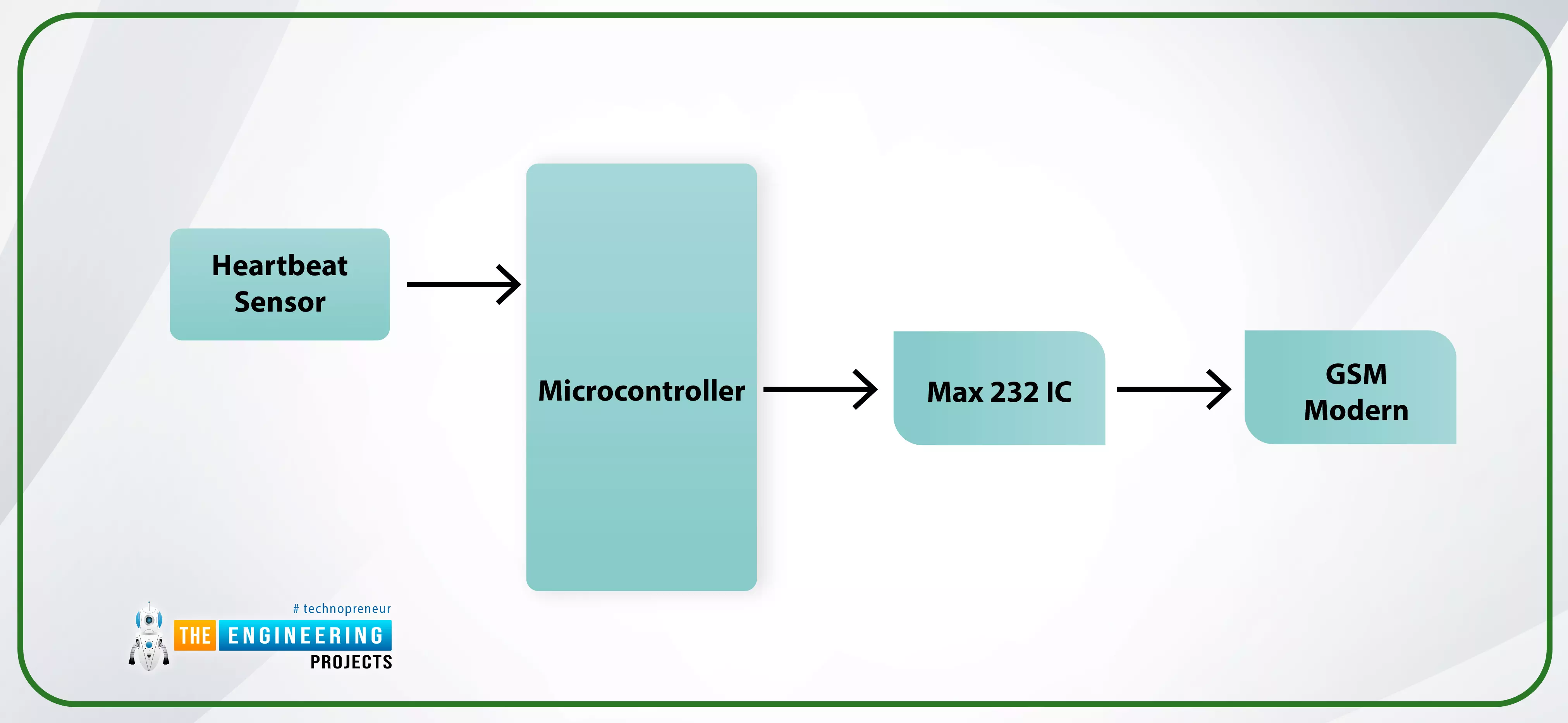
The data collected by the heartbeat detector (a light-emitting device whose light is modified as it flows through human blood) is transformed into electrical pulses at the transmitter unit. When the Microcontroller picks up on these pulses, it calculates the heart rate and communicates that information and other data collected to the medical team via a Gsm network. An IC called a Max 232 connects the Microcontroller to the GSM modem.
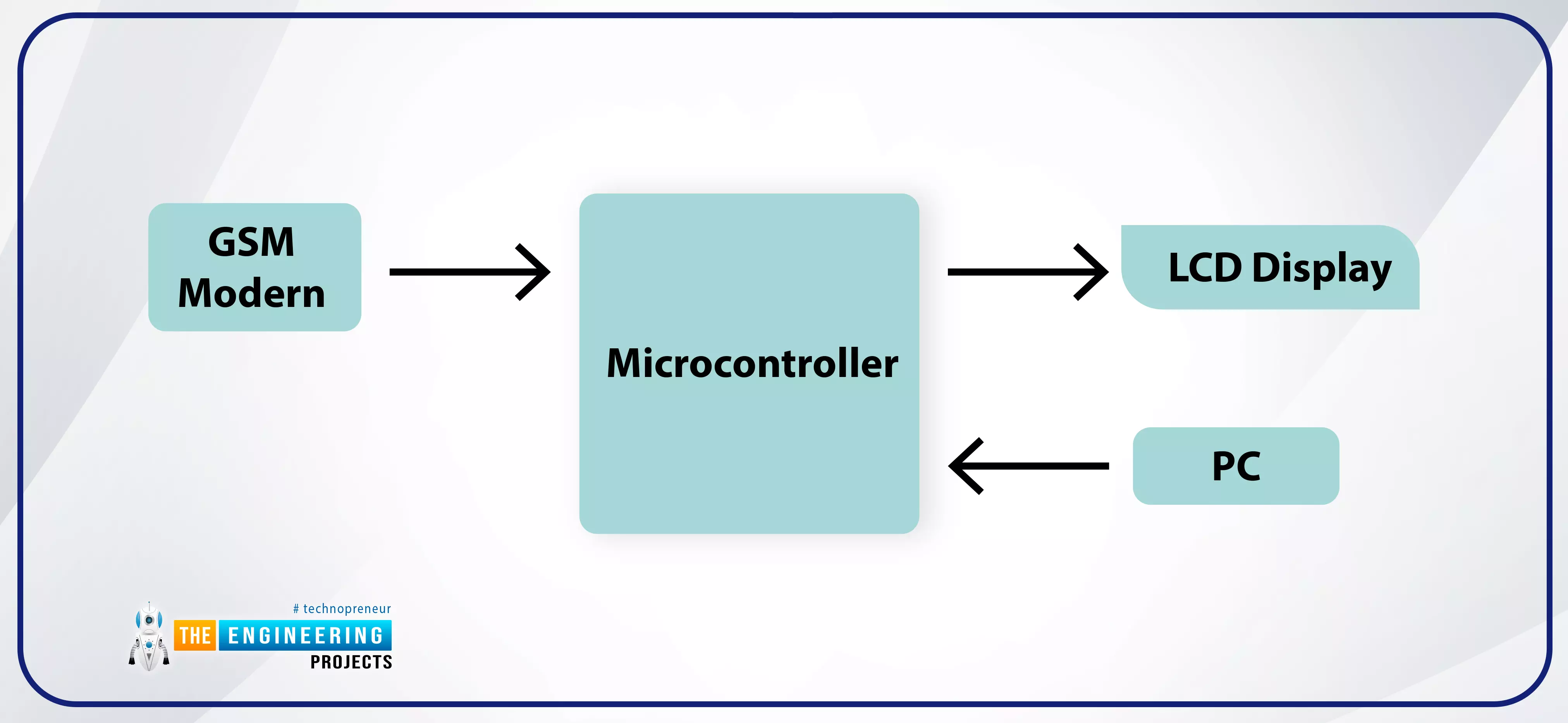
The GSM modem at the receiving end grabs the information and passes it to the Microcontroller. The Microcontroller then performs an analysis using the input from the Personal computer and displays the outcome on the LCD. Medical professionals can keep tabs on the patient and begin the necessary treatment after reviewing the results on the screen.
Medical Applications of Global Systems for Mobile Communication
The following are some real-world applications for GSM technology.
AT&T Health GlowCaps
These plain pill bottles serve as a gentle prompt to the patient to take their prescribed medications. It uses GSM technology to contact the patient on their mobile phone at the specified pill-taking time, at which point the cap will light up, the buzzer will sound, and the patient will be reminded to take their medication. Each time a bottle is uncorked, it is documented.
Ultrasound technology
With the help of a portable ultrasound transducer that connects to a smartphone, it is possible to send ultrasound images captured with a handheld device to a distant location using a global system for mobile communications (GSM).
A Continuous Glucose Monitor (CGM)
The patient's blood sugar levels can be tracked and reported to the doctor. A sensor is implanted under the skin and monitors blood glucose levels, sending the data to a receiver (a mobile phone) at regular intervals.
Conclusion
As part of this guide, we analyzed GSM's architecture and learned how it operates in practice. We wrote a Python program to turn our Raspberry Pi 4 into a fully functional mobile phone. No technical difficulties were encountered as we watched text and phone calls travel between the raspberry pi and our mobile phone. You should feel confident in your ability to apply the ideas and understand the circuits of GSM now. One way to up the difficulty level of this Project is to try to make a live video call using the raspberry pi 4 mobile. Next, we'll look at connecting the pcf8591 ADC/DAC analog-digital converter module to a Raspberry Pi.


